oil SUZUKI SWIFT 2000 1.G RG413 Service User Guide
[x] Cancel search | Manufacturer: SUZUKI, Model Year: 2000, Model line: SWIFT, Model: SUZUKI SWIFT 2000 1.GPages: 698, PDF Size: 16.01 MB
Page 33 of 698
0B-4 MAINTENANCE AND LUBRICATION
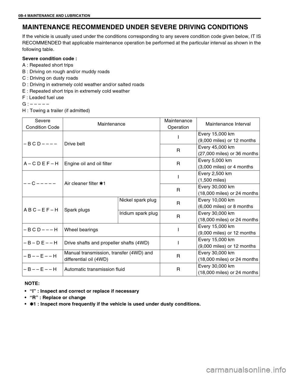
MAINTENANCE RECOMMENDED UNDER SEVERE DRIVING CONDITIONS
If the vehicle is usually used under the conditions corresponding to any severe condition code given below, IT IS
RECOMMENDED that applicable maintenance operation be performed at the particular interval as shown in the
following table.
Severe condition code :
A : Repeated short trips
B : Driving on rough and/or muddy roads
C : Driving on dusty roads
D : Driving in extremely cold weather and/or salted roads
E : Repeated short trips in extremely cold weather
F : Leaded fuel use
G : – – – – –
H : Towing a trailer (if admitted)
Severe
Condition CodeMaintenanceMaintenance
OperationMaintenance Interval
– B C D – – – –Drive beltIEvery 15,000 km
(9,000 miles) or 12 months
REvery 45,000 km
(27,000 miles) or 36 months
A – C D E F – H Engine oil and oil filter REvery 5,000 km
(3,000 miles) or 4 months
– – C – – – – –Air cleaner filter ✱1IEvery 2,500 km
(1,500 miles)
REvery 30,000 km
(18,000 miles) or 24 months
A B C – E F – H Spark plugsNickel spark plug
REvery 10,000 km
(6,000 miles) or 8 months
Iridium spark plug
REvery 30,000 km
(18,000 miles) or 24 months
– B C D – – – H Wheel bearings IEvery 15,000 km
(9,000 miles) or 12 months
– B – D E – – H Drive shafts and propeller shafts (4WD) IEvery 15,000 km
(9,000 miles) or 12 months
– B – – E – – HManual transmission, transfer (4WD) and
differential oil (4WD)REvery 30,000 km
(18,000 miles) or 24 months
– B – – E – – H Automatic transmission fluid REvery 30,000 km
(18,000 miles) or 24 months
NOTE:
“I” : Inspect and correct or replace if necessary
“R” : Replace or change
✱
✱✱ ✱1 : Inspect more frequently if the vehicle is used under dusty conditions.
Page 35 of 698
0B-6 MAINTENANCE AND LUBRICATION
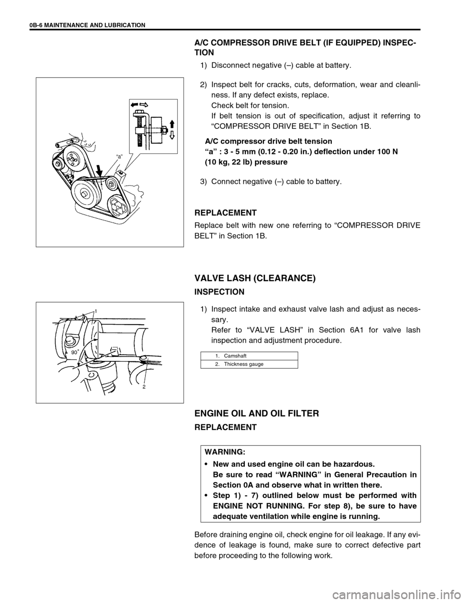
A/C COMPRESSOR DRIVE BELT (IF EQUIPPED) INSPEC-
TION
1) Disconnect negative (–) cable at battery.
2) Inspect belt for cracks, cuts, deformation, wear and cleanli-
ness. If any defect exists, replace.
Check belt for tension.
If belt tension is out of specification, adjust it referring to
“COMPRESSOR DRIVE BELT” in Section 1B.
A/C compressor drive belt tension
“a” : 3 - 5 mm (0.12 - 0.20 in.) deflection under 100 N
(10 kg, 22 lb) pressure
3) Connect negative (–) cable to battery.
REPLACEMENT
Replace belt with new one referring to “COMPRESSOR DRIVE
BELT” in Section 1B.
VALVE LASH (CLEARANCE)
INSPECTION
1) Inspect intake and exhaust valve lash and adjust as neces-
sary.
Refer to “VALVE LASH” in Section 6A1 for valve lash
inspection and adjustment procedure.
ENGINE OIL AND OIL FILTER
REPLACEMENT
Before draining engine oil, check engine for oil leakage. If any evi-
dence of leakage is found, make sure to correct defective part
before proceeding to the following work.
1. Camshaft
2. Thickness gauge
WARNING:
New and used engine oil can be hazardous.
Be sure to read “WARNING” in General Precaution in
Section 0A and observe what in written there.
Step 1) - 7) outlined below must be performed with
ENGINE NOT RUNNING. For step 8), be sure to have
adequate ventilation while engine is running.
Page 36 of 698
MAINTENANCE AND LUBRICATION 0B-7
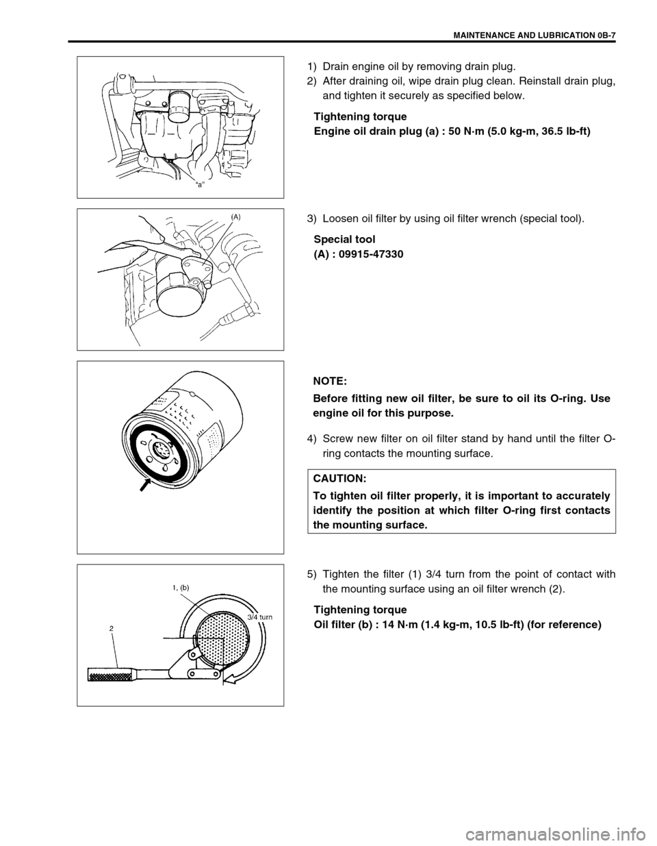
1) Drain engine oil by removing drain plug.
2) After draining oil, wipe drain plug clean. Reinstall drain plug,
and tighten it securely as specified below.
Tightening torque
Engine oil drain plug (a) : 50 N·m (5.0 kg-m, 36.5 lb-ft)
3) Loosen oil filter by using oil filter wrench (special tool).
Special tool
(A) : 09915-47330
4) Screw new filter on oil filter stand by hand until the filter O-
ring contacts the mounting surface.
5) Tighten the filter (1) 3/4 turn from the point of contact with
the mounting surface using an oil filter wrench (2).
Tightening torque
Oil filter (b) : 14 N·m (1.4 kg-m, 10.5 lb-ft) (for reference)
NOTE:
Before fitting new oil filter, be sure to oil its O-ring. Use
engine oil for this purpose.
CAUTION:
To tighten oil filter properly, it is important to accurately
identify the position at which filter O-ring first contacts
the mounting surface.
Page 37 of 698
0B-8 MAINTENANCE AND LUBRICATION
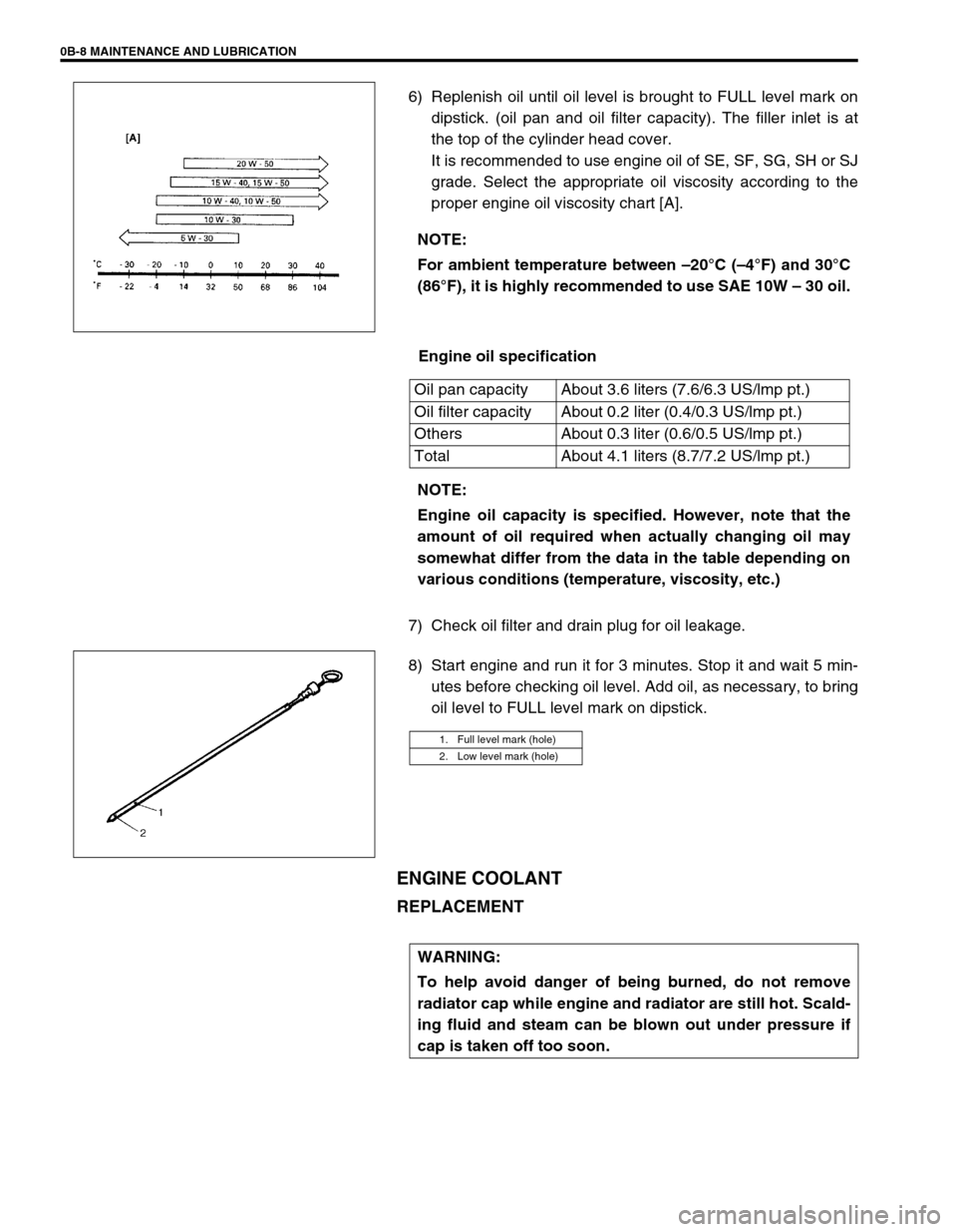
6) Replenish oil until oil level is brought to FULL level mark on
dipstick. (oil pan and oil filter capacity). The filler inlet is at
the top of the cylinder head cover.
It is recommended to use engine oil of SE, SF, SG, SH or SJ
grade. Select the appropriate oil viscosity according to the
proper engine oil viscosity chart [A].
Engine oil specification
7) Check oil filter and drain plug for oil leakage.
8) Start engine and run it for 3 minutes. Stop it and wait 5 min-
utes before checking oil level. Add oil, as necessary, to bring
oil level to FULL level mark on dipstick.
ENGINE COOLANT
REPLACEMENT
NOTE:
For ambient temperature between –20°C (–4°F) and 30°C
(86°F), it is highly recommended to use SAE 10W – 30 oil.
Oil pan capacity About 3.6 liters (7.6/6.3 US/lmp pt.)
Oil filter capacity About 0.2 liter (0.4/0.3 US/lmp pt.)
Others About 0.3 liter (0.6/0.5 US/lmp pt.)
Total About 4.1 liters (8.7/7.2 US/lmp pt.)
NOTE:
Engine oil capacity is specified. However, note that the
amount of oil required when actually changing oil may
somewhat differ from the data in the table depending on
various conditions (temperature, viscosity, etc.)
1. Full level mark (hole)
2. Low level mark (hole)
WARNING:
To help avoid danger of being burned, do not remove
radiator cap while engine and radiator are still hot. Scald-
ing fluid and steam can be blown out under pressure if
cap is taken off too soon.
Page 39 of 698
0B-10 MAINTENANCE AND LUBRICATION
EXHAUST SYSTEM
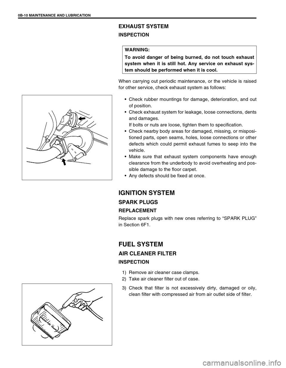
INSPECTION
When carrying out periodic maintenance, or the vehicle is raised
for other service, check exhaust system as follows:
Check rubber mountings for damage, deterioration, and out
of position.
Check exhaust system for leakage, loose connections, dents
and damages.
If bolts or nuts are loose, tighten them to specification.
Check nearby body areas for damaged, missing, or misposi-
tioned parts, open seams, holes, loose connections or other
defects which could permit exhaust fumes to seep into the
vehicle.
Make sure that exhaust system components have enough
clearance from the underbody to avoid overheating and pos-
sible damage to the floor carpet.
Any defects should be fixed at once.
IGNITION SYSTEM
SPARK PLUGS
REPLACEMENT
Replace spark plugs with new ones referring to “SPARK PLUG”
in Section 6F1.
FUEL SYSTEM
AIR CLEANER FILTER
INSPECTION
1) Remove air cleaner case clamps.
2) Take air cleaner filter out of case.
3) Check that filter is not excessively dirty, damaged or oily,
clean filter with compressed air from air outlet side of filter. WARNING:
To avoid danger of being burned, do not touch exhaust
system when it is still hot. Any service on exhaust sys-
tem should be performed when it is cool.
Page 44 of 698
MAINTENANCE AND LUBRICATION 0B-15
WHEEL DISCS INSPECTION
Inspect each wheel disc for dents, distortion and cracks. A disc in
badly damaged condition must be replaced.
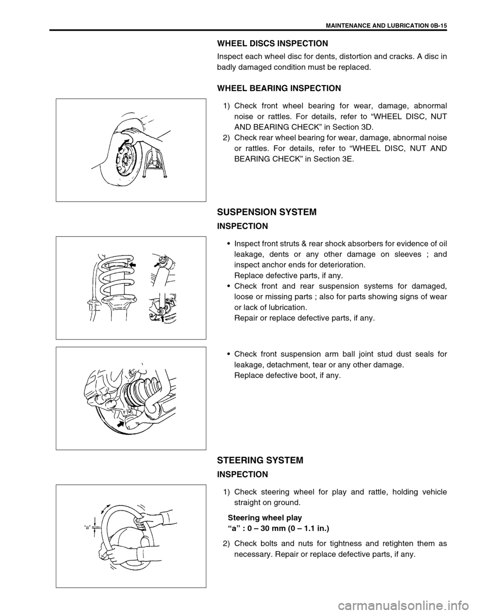
WHEEL BEARING INSPECTION
1) Check front wheel bearing for wear, damage, abnormal
noise or rattles. For details, refer to “WHEEL DISC, NUT
AND BEARING CHECK” in Section 3D.
2) Check rear wheel bearing for wear, damage, abnormal noise
or rattles. For details, refer to “WHEEL DISC, NUT AND
BEARING CHECK” in Section 3E.
SUSPENSION SYSTEM
INSPECTION
Inspect front struts & rear shock absorbers for evidence of oil
leakage, dents or any other damage on sleeves ; and
inspect anchor ends for deterioration.
Replace defective parts, if any.
Check front and rear suspension systems for damaged,
loose or missing parts ; also for parts showing signs of wear
or lack of lubrication.
Repair or replace defective parts, if any.
Check front suspension arm ball joint stud dust seals for
leakage, detachment, tear or any other damage.
Replace defective boot, if any.
STEERING SYSTEM
INSPECTION
1) Check steering wheel for play and rattle, holding vehicle
straight on ground.
Steering wheel play
“a” : 0 – 30 mm (0 – 1.1 in.)
2) Check bolts and nuts for tightness and retighten them as
necessary. Repair or replace defective parts, if any.
Page 46 of 698
MAINTENANCE AND LUBRICATION 0B-17
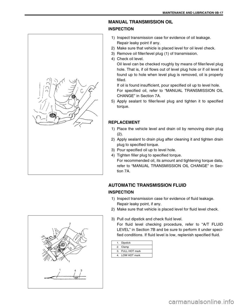
MANUAL TRANSMISSION OIL
INSPECTION
1) Inspect transmission case for evidence of oil leakage.
Repair leaky point if any.
2) Make sure that vehicle is placed level for oil level check.
3) Remove oil filler/level plug (1) of transmission.
4) Check oil level.
Oil level can be checked roughly by means of filler/level plug
hole. That is, if oil flows out of level plug hole or if oil level is
found up to hole when level plug is removed, oil is properly
filled.
If oil is found insufficient, pour specified oil up to level hole.
For specified oil, refer to “MANUAL TRANSMISSION OIL
CHANGE” in Section 7A.
5) Apply sealant to filler/level plug and tighten it to specified
torque.
REPLACEMENT
1) Place the vehicle level and drain oil by removing drain plug
(2).
2) Apply sealant to drain plug after cleaning it and tighten drain
plug to specified torque.
3) Pour specified oil up to level hole.
4) Tighten filler plug to specified torque.
For recommended oil, its amount and tightening torque data,
refer to “MANUAL TRANSMISSION OIL CHANGE” in Sec-
tion 7A.
AUTOMATIC TRANSMISSION FLUID
INSPECTION
1) Inspect transmission case for evidence of fluid leakage.
Repair leaky point, if any.
2) Make sure that vehicle is placed level for fluid level check.
3) Pull out dipstick and check fluid level.
For fluid level checking procedure, refer to “A/T FLUID
LEVEL” in Section 7B and be sure to perform it under speci-
fied conditions. If fluid level is low, replenish specified fluid.
1. Dipstick
2. Clamp
3. FULL HOT mark
4. LOW HOT mark
Page 47 of 698
0B-18 MAINTENANCE AND LUBRICATION
REPLACEMENT
1) Inspect transmission case for evidence of fluid leakage.
Repair leaky point, if any.
2) Make sure that vehicle is placed level for fluid level check.
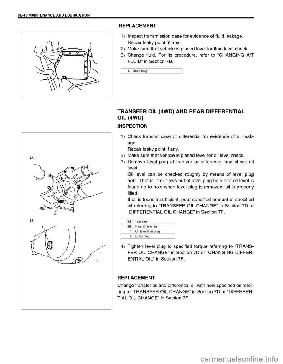
3) Change fluid. For its procedure, refer to “CHANGING A/T
FLUID” in Section 7B.
TRANSFER OIL (4WD) AND REAR DIFFERENTIAL
OIL (4WD)
INSPECTION
1) Check transfer case or differential for evidence of oil leak-
age.
Repair leaky point if any.
2) Make sure that vehicle is placed level for oil level check.
3) Remove level plug of transfer or differential and check oil
level.
Oil level can be checked roughly by means of level plug
hole. That is, if oil flows out of level plug hole or if oil level is
found up to hole when level plug is removed, oil is properly
filled.
If oil is found insufficient, pour specified amount of specified
oil referring to “TRANSFER OIL CHANGE” in Section 7D or
“DIFFERENTIAL OIL CHANGE” in Section 7F.
4) Tighten level plug to specified torque referring to “TRANS-
FER OIL CHANGE” in Section 7D or “CHANGING DIFFER-
ENTIAL OIL” in Section 7F.
REPLACEMENT
Change transfer oil and differential oil with new specified oil refer-
ring to “TRANSFER OIL CHANGE” in Section 7D or “DIFFEREN-
TIAL OIL CHANGE” in Section 7F.
1. Drain plug
[A] : Transfer
[B] : Rear differential
1. Oil level/filler plug
2. Drain plug
Page 50 of 698
MAINTENANCE AND LUBRICATION 0B-21
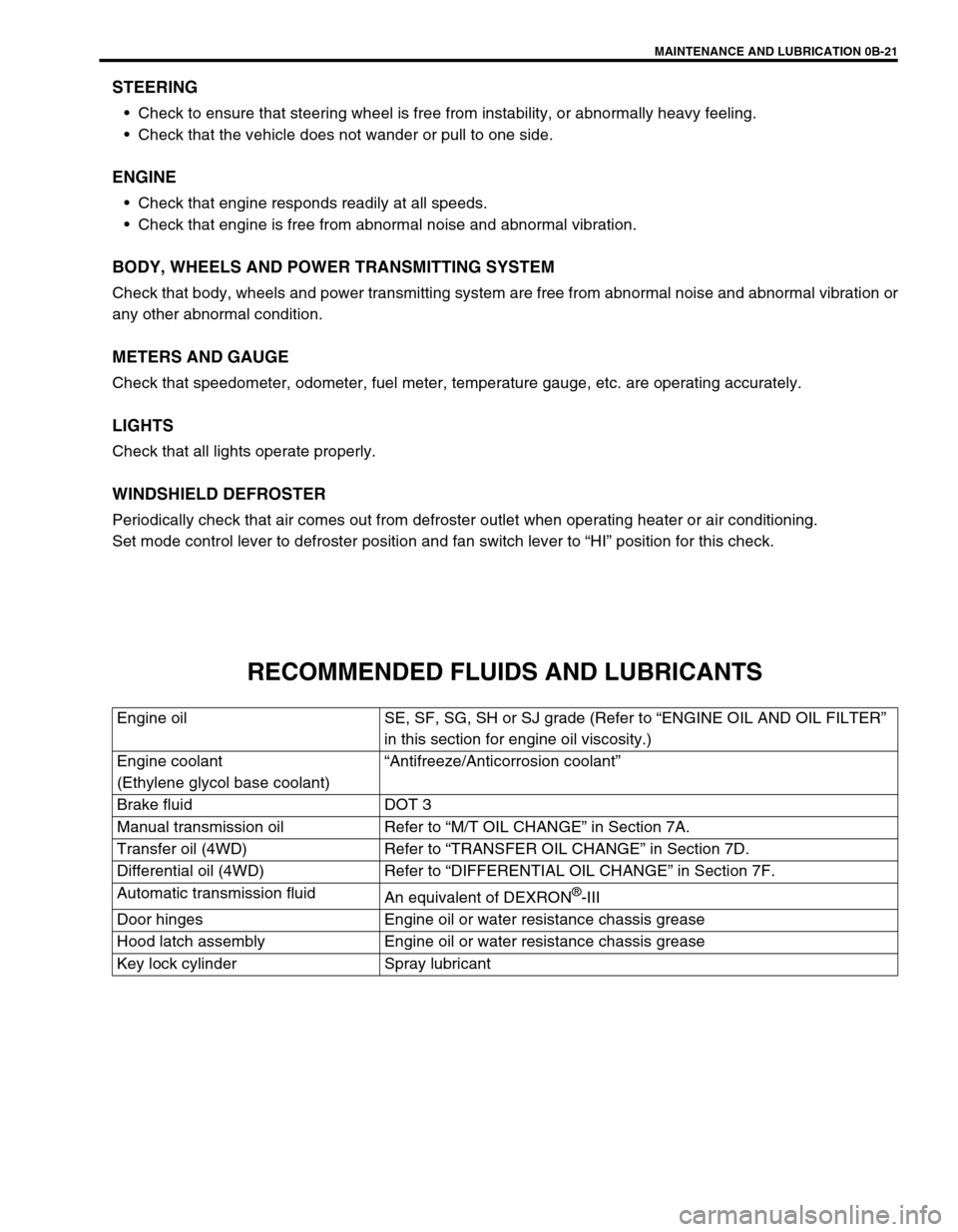
STEERING
Check to ensure that steering wheel is free from instability, or abnormally heavy feeling.
Check that the vehicle does not wander or pull to one side.
ENGINE
Check that engine responds readily at all speeds.
Check that engine is free from abnormal noise and abnormal vibration.
BODY, WHEELS AND POWER TRANSMITTING SYSTEM
Check that body, wheels and power transmitting system are free from abnormal noise and abnormal vibration or
any other abnormal condition.
METERS AND GAUGE
Check that speedometer, odometer, fuel meter, temperature gauge, etc. are operating accurately.
LIGHTS
Check that all lights operate properly.
WINDSHIELD DEFROSTER
Periodically check that air comes out from defroster outlet when operating heater or air conditioning.
Set mode control lever to defroster position and fan switch lever to “HI” position for this check.
RECOMMENDED FLUIDS AND LUBRICANTS
Engine oil SE, SF, SG, SH or SJ grade (Refer to “ENGINE OIL AND OIL FILTER”
in this section for engine oil viscosity.)
Engine coolant
(Ethylene glycol base coolant)“Antifreeze/Anticorrosion coolant”
Brake fluid DOT 3
Manual transmission oil Refer to “M/T OIL CHANGE” in Section 7A.
Transfer oil (4WD) Refer to “TRANSFER OIL CHANGE” in Section 7D.
Differential oil (4WD) Refer to “DIFFERENTIAL OIL CHANGE” in Section 7F.
Automatic transmission fluid
An equivalent of DEXRON
®-III
Door hinges Engine oil or water resistance chassis grease
Hood latch assembly Engine oil or water resistance chassis grease
Key lock cylinder Spray lubricant
Page 66 of 698
AIR CONDITIONING (OPTIONAL) 1B-1
6F1
6F2
6G
1B
7A
7A1
7B1
7C1
7D
7E
7F
8A
8B
8C
8D
8E
9
10
10A
10B
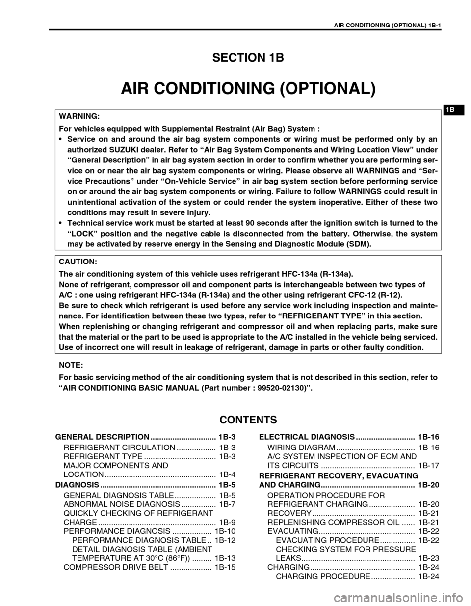
SECTION 1B
AIR CONDITIONING (OPTIONAL)
CONTENTS
GENERAL DESCRIPTION .............................. 1B-3
REFRIGERANT CIRCULATION .................. 1B-3
REFRIGERANT TYPE ................................. 1B-3
MAJOR COMPONENTS AND
LOCATION ................................................... 1B-4
DIAGNOSIS ..................................................... 1B-5
GENERAL DIAGNOSIS TABLE ................... 1B-5
ABNORMAL NOISE DIAGNOSIS ................ 1B-7
QUICKLY CHECKING OF REFRIGERANT
CHARGE ...................................................... 1B-9
PERFORMANCE DIAGNOSIS .................. 1B-10
PERFORMANCE DIAGNOSIS TABLE .. 1B-12
DETAIL DIAGNOSIS TABLE (AMBIENT
TEMPERATURE AT 30°C (86°F)) ......... 1B-13
COMPRESSOR DRIVE BELT ................... 1B-15ELECTRICAL DIAGNOSIS ........................... 1B-16
WIRING DIAGRAM .................................... 1B-16
A/C SYSTEM INSPECTION OF ECM AND
ITS CIRCUITS ........................................... 1B-17
REFRIGERANT RECOVERY, EVACUATING
AND CHARGING........................................... 1B-20
OPERATION PROCEDURE FOR
REFRIGERANT CHARGING ..................... 1B-20
RECOVERY ............................................... 1B-21
REPLENISHING COMPRESSOR OIL ...... 1B-21
EVACUATING............................................ 1B-22
EVACUATING PROCEDURE ................ 1B-22
CHECKING SYSTEM FOR PRESSURE
LEAKS.................................................... 1B-23
CHARGING................................................ 1B-24
CHARGING PROCEDURE .................... 1B-24 WARNING:
For vehicles equipped with Supplemental Restraint (Air Bag) System :
Service on and around the air bag system components or wiring must be performed only by an
authorized SUZUKI dealer. Refer to “Air Bag System Components and Wiring Location View” under
“General Description” in air bag system section in order to confirm whether you are performing ser-
vice on or near the air bag system components or wiring. Please observe all WARNINGS and “Ser-
vice Precautions” under “On-Vehicle Service” in air bag system section before performing service
on or around the air bag system components or wiring. Failure to follow WARNINGS could result in
unintentional activation of the system or could render the system inoperative. Either of these two
conditions may result in severe injury.
Technical service work must be started at least 90 seconds after the ignition switch is turned to the
“LOCK” position and the negative cable is disconnected from the battery. Otherwise, the system
may be activated by reserve energy in the Sensing and Diagnostic Module (SDM).
CAUTION:
The air conditioning system of this vehicle uses refrigerant HFC-134a (R-134a).
None of refrigerant, compressor oil and component parts is interchangeable between two types of
A/C : one using refrigerant HFC-134a (R-134a) and the other using refrigerant CFC-12 (R-12).
Be sure to check which refrigerant is used before any service work including inspection and mainte-
nance. For identification between these two types, refer to “REFRIGERANT TYPE” in this section.
When replenishing or changing refrigerant and compressor oil and when replacing parts, make sure
that the material or the part to be used is appropriate to the A/C installed in the vehicle being serviced.
Use of incorrect one will result in leakage of refrigerant, damage in parts or other faulty condition.
NOTE:
For basic servicing method of the air conditioning system that is not described in this section, refer to
“AIR CONDITIONING BASIC MANUAL (Part number : 99520-02130)”.