oil SUZUKI SWIFT 2000 1.G RG413 Service Owner's Manual
[x] Cancel search | Manufacturer: SUZUKI, Model Year: 2000, Model line: SWIFT, Model: SUZUKI SWIFT 2000 1.GPages: 698, PDF Size: 16.01 MB
Page 71 of 698
1B-6 AIR CONDITIONING (OPTIONAL)
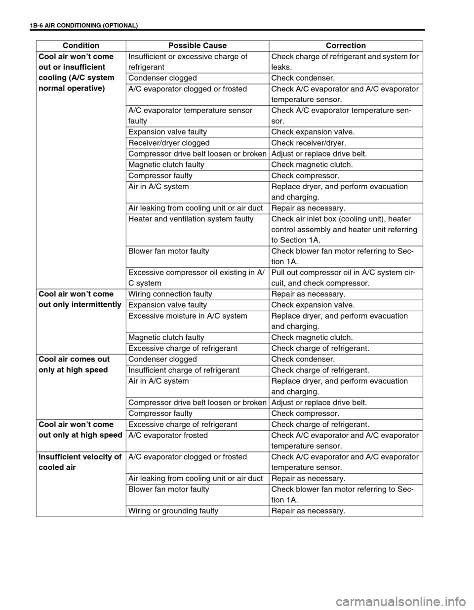
Cool air won’t come
out or insufficient
cooling (A/C system
normal operative)Insufficient or excessive charge of
refrigerantCheck charge of refrigerant and system for
leaks.
Condenser clogged Check condenser.
A/C evaporator clogged or frosted Check A/C evaporator and A/C evaporator
temperature sensor.
A/C evaporator temperature sensor
faultyCheck A/C evaporator temperature sen-
sor.
Expansion valve faulty Check expansion valve.
Receiver/dryer clogged Check receiver/dryer.
Compressor drive belt loosen or broken Adjust or replace drive belt.
Magnetic clutch faulty Check magnetic clutch.
Compressor faulty Check compressor.
Air in A/C system Replace dryer, and perform evacuation
and charging.
Air leaking from cooling unit or air duct Repair as necessary.
Heater and ventilation system faulty Check air inlet box (cooling unit), heater
control assembly and heater unit referring
to Section 1A.
Blower fan motor faulty Check blower fan motor referring to Sec-
tion 1A.
Excessive compressor oil existing in A/
C systemPull out compressor oil in A/C system cir-
cuit, and check compressor.
Cool air won’t come
out only intermittentlyWiring connection faulty Repair as necessary.
Expansion valve faulty Check expansion valve.
Excessive moisture in A/C system Replace dryer, and perform evacuation
and charging.
Magnetic clutch faulty Check magnetic clutch.
Excessive charge of refrigerant Check charge of refrigerant.
Cool air comes out
only at high speedCondenser clogged Check condenser.
Insufficient charge of refrigerant Check charge of refrigerant.
Air in A/C system Replace dryer, and perform evacuation
and charging.
Compressor drive belt loosen or broken Adjust or replace drive belt.
Compressor faulty Check compressor.
Cool air won’t come
out only at high speedExcessive charge of refrigerant Check charge of refrigerant.
A/C evaporator frosted Check A/C evaporator and A/C evaporator
temperature sensor.
Insufficient velocity of
cooled airA/C evaporator clogged or frosted Check A/C evaporator and A/C evaporator
temperature sensor.
Air leaking from cooling unit or air duct Repair as necessary.
Blower fan motor faulty Check blower fan motor referring to Sec-
tion 1A.
Wiring or grounding faulty Repair as necessary. Condition Possible Cause Correction
Page 72 of 698
AIR CONDITIONING (OPTIONAL) 1B-7
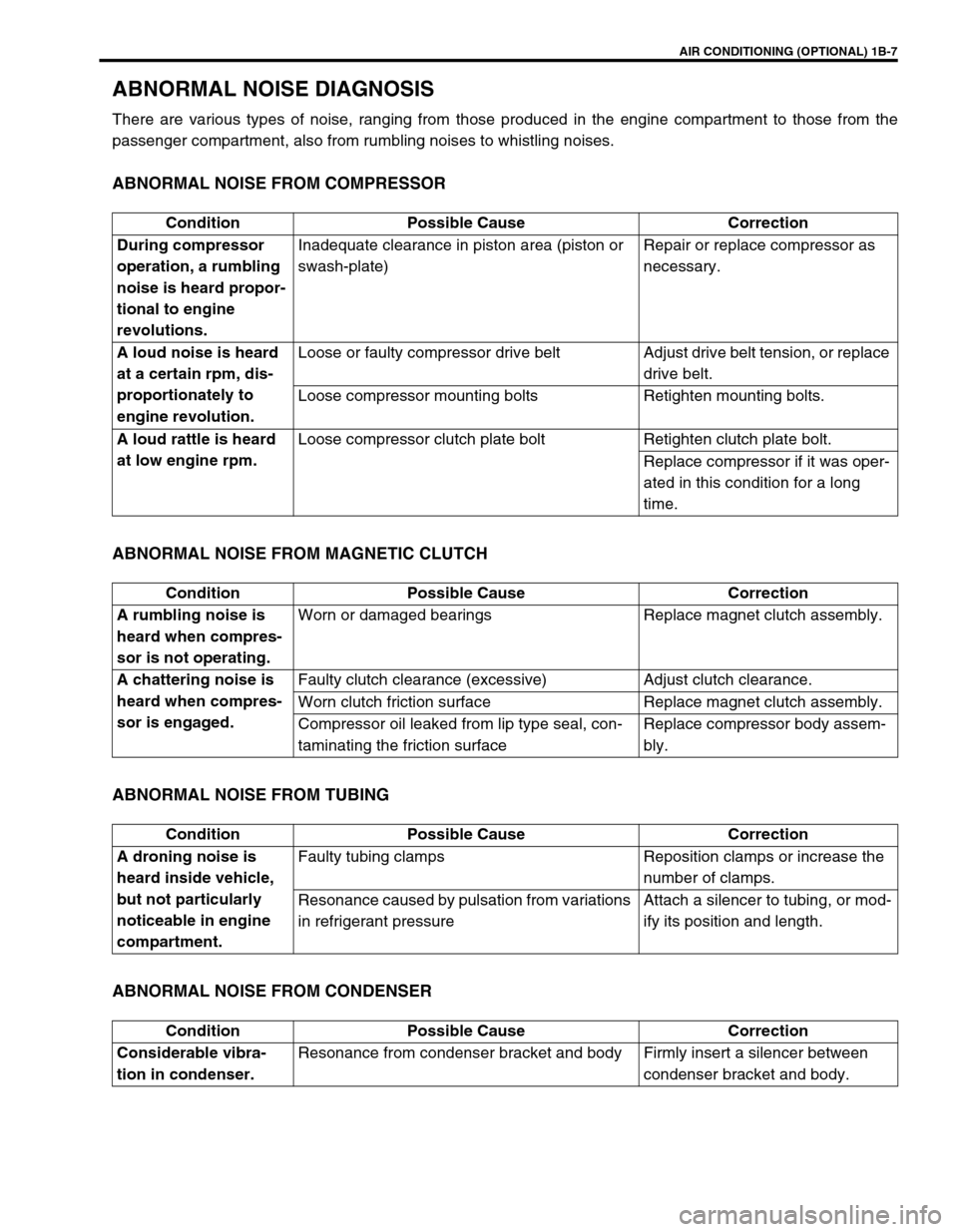
ABNORMAL NOISE DIAGNOSIS
There are various types of noise, ranging from those produced in the engine compartment to those from the
passenger compartment, also from rumbling noises to whistling noises.
ABNORMAL NOISE FROM COMPRESSOR
ABNORMAL NOISE FROM MAGNETIC CLUTCH
ABNORMAL NOISE FROM TUBING
ABNORMAL NOISE FROM CONDENSER
Condition Possible Cause Correction
During compressor
operation, a rumbling
noise is heard propor-
tional to engine
revolutions.Inadequate clearance in piston area (piston or
swash-plate)Repair or replace compressor as
necessary.
A loud noise is heard
at a certain rpm, dis-
proportionately to
engine revolution.Loose or faulty compressor drive belt Adjust drive belt tension, or replace
drive belt.
Loose compressor mounting bolts Retighten mounting bolts.
A loud rattle is heard
at low engine rpm.Loose compressor clutch plate bolt Retighten clutch plate bolt.
Replace compressor if it was oper-
ated in this condition for a long
time.
Condition Possible Cause Correction
A rumbling noise is
heard when compres-
sor is not operating.Worn or damaged bearings Replace magnet clutch assembly.
A chattering noise is
heard when compres-
sor is engaged.Faulty clutch clearance (excessive) Adjust clutch clearance.
Worn clutch friction surface Replace magnet clutch assembly.
Compressor oil leaked from lip type seal, con-
taminating the friction surfaceReplace compressor body assem-
bly.
Condition Possible Cause Correction
A droning noise is
heard inside vehicle,
but not particularly
noticeable in engine
compartment.Faulty tubing clamps Reposition clamps or increase the
number of clamps.
Resonance caused by pulsation from variations
in refrigerant pressureAttach a silencer to tubing, or mod-
ify its position and length.
Condition Possible Cause Correction
Considerable vibra-
tion in condenser.Resonance from condenser bracket and body Firmly insert a silencer between
condenser bracket and body.
Page 77 of 698
1B-12 AIR CONDITIONING (OPTIONAL)
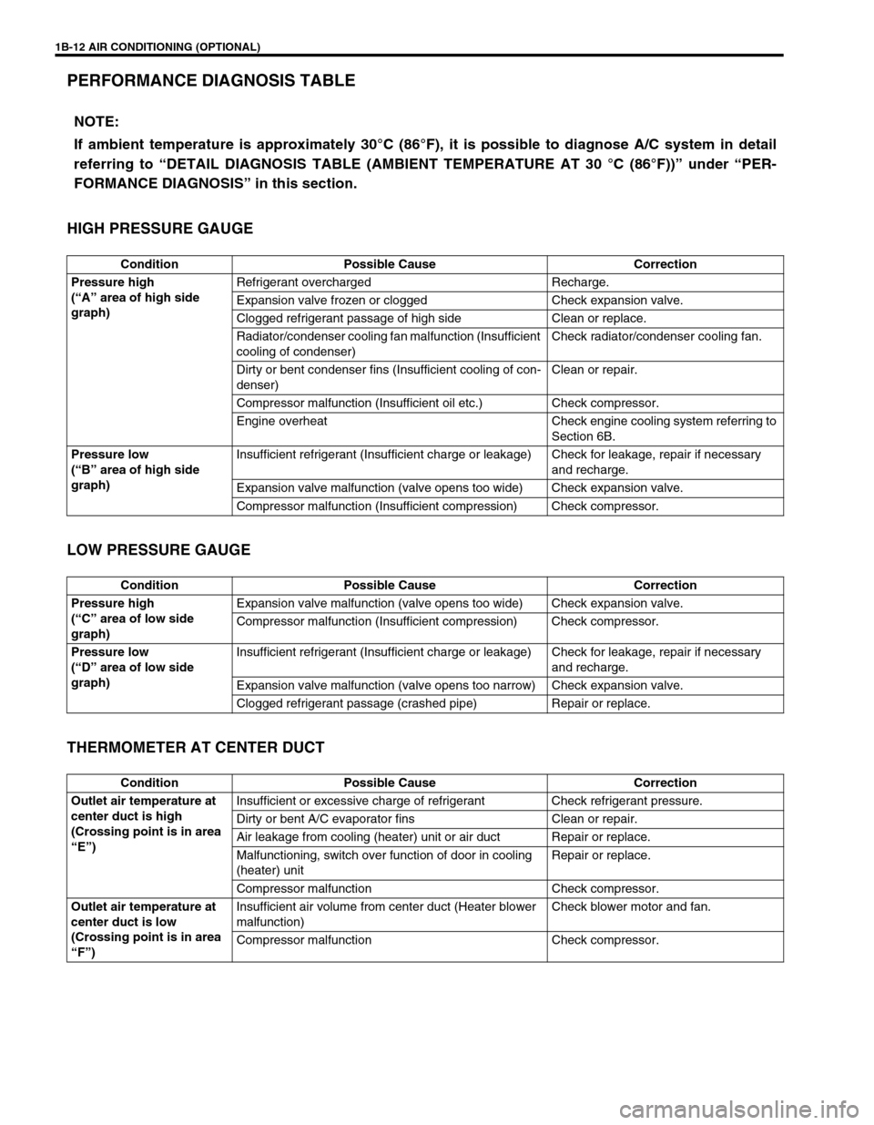
PERFORMANCE DIAGNOSIS TABLE
HIGH PRESSURE GAUGE
LOW PRESSURE GAUGE
THERMOMETER AT CENTER DUCT
NOTE:
If ambient temperature is approximately 30°C (86°F), it is possible to diagnose A/C system in detail
referring to “DETAIL DIAGNOSIS TABLE (AMBIENT TEMPERATURE AT 30 °C (86°F))” under “PER-
FORMANCE DIAGNOSIS” in this section.
Condition Possible Cause Correction
Pressure high
(“A” area of high side
graph)Refrigerant overcharged Recharge.
Expansion valve frozen or clogged Check expansion valve.
Clogged refrigerant passage of high side Clean or replace.
Radiator/condenser cooling fan malfunction (Insufficient
cooling of condenser)Check radiator/condenser cooling fan.
Dirty or bent condenser fins (Insufficient cooling of con-
denser)Clean or repair.
Compressor malfunction (Insufficient oil etc.) Check compressor.
Engine overheat Check engine cooling system referring to
Section 6B.
Pressure low
(“B” area of high side
graph)Insufficient refrigerant (Insufficient charge or leakage) Check for leakage, repair if necessary
and recharge.
Expansion valve malfunction (valve opens too wide) Check expansion valve.
Compressor malfunction (Insufficient compression) Check compressor.
Condition Possible Cause Correction
Pressure high
(“C” area of low side
graph)Expansion valve malfunction (valve opens too wide) Check expansion valve.
Compressor malfunction (Insufficient compression) Check compressor.
Pressure low
(“D” area of low side
graph)Insufficient refrigerant (Insufficient charge or leakage) Check for leakage, repair if necessary
and recharge.
Expansion valve malfunction (valve opens too narrow) Check expansion valve.
Clogged refrigerant passage (crashed pipe) Repair or replace.
Condition Possible Cause Correction
Outlet air temperature at
center duct is high
(Crossing point is in area
“E”)Insufficient or excessive charge of refrigerant Check refrigerant pressure.
Dirty or bent A/C evaporator fins Clean or repair.
Air leakage from cooling (heater) unit or air duct Repair or replace.
Malfunctioning, switch over function of door in cooling
(heater) unitRepair or replace.
Compressor malfunction Check compressor.
Outlet air temperature at
center duct is low
(Crossing point is in area
“F”)Insufficient air volume from center duct (Heater blower
malfunction)Check blower motor and fan.
Compressor malfunction Check compressor.
Page 79 of 698
1B-14 AIR CONDITIONING (OPTIONAL)
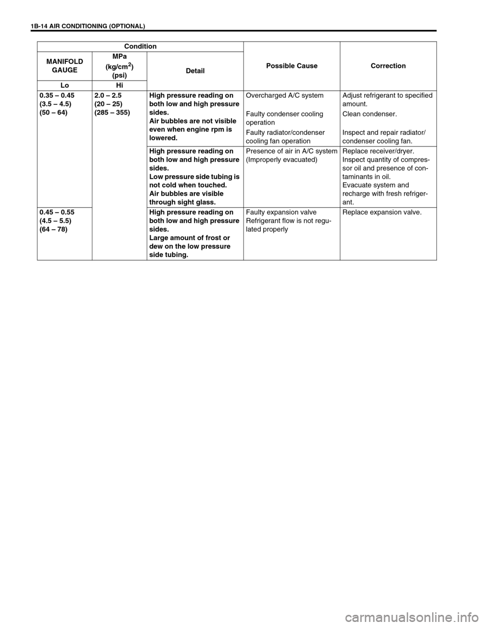
0.35 – 0.45
(3.5 – 4.5)
(50 – 64)2.0 – 2.5
(20 – 25)
(285 – 355)High pressure reading on
both low and high pressure
sides.
Air bubbles are not visible
even when engine rpm is
lowered.Overcharged A/C system Adjust refrigerant to specified
amount.
Faulty condenser cooling
operationClean condenser.
Faulty radiator/condenser
cooling fan operationInspect and repair radiator/
condenser cooling fan.
High pressure reading on
both low and high pressure
sides.
Low pressure side tubing is
not cold when touched.
Air bubbles are visible
through sight glass.Presence of air in A/C system
(Improperly evacuated)Replace receiver/dryer.
Inspect quantity of compres-
sor oil and presence of con-
taminants in oil.
Evacuate system and
recharge with fresh refriger-
ant.
0.45 – 0.55
(4.5 – 5.5)
(64 – 78)High pressure reading on
both low and high pressure
sides.
Large amount of frost or
dew on the low pressure
side tubing.Faulty expansion valve
Refrigerant flow is not regu-
lated properlyReplace expansion valve. Condition
Possible Cause Correction MANIFOLD
GAUGEMPa
(kg/cm
2)
(psi)Detail
Lo Hi
Page 85 of 698
1B-20 AIR CONDITIONING (OPTIONAL)
REFRIGERANT RECOVERY, EVACUATING AND CHARGING
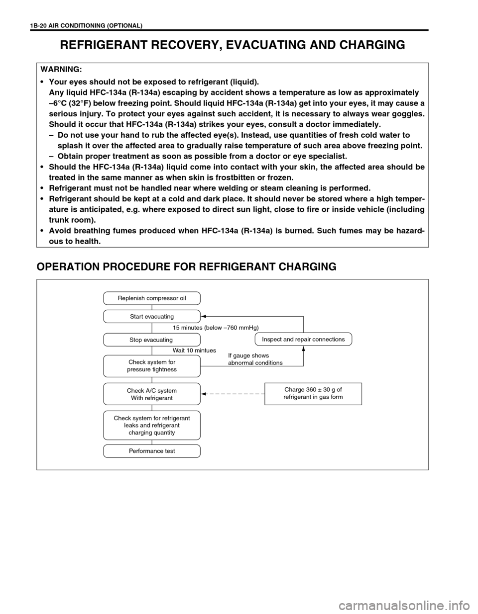
OPERATION PROCEDURE FOR REFRIGERANT CHARGING
WARNING:
Your eyes should not be exposed to refrigerant (liquid).
Any liquid HFC-134a (R-134a) escaping by accident shows a temperature as low as approximately
–6°C (32°F) below freezing point. Should liquid HFC-134a (R-134a) get into your eyes, it may cause a
serious injury. To protect your eyes against such accident, it is necessary to always wear goggles.
Should it occur that HFC-134a (R-134a) strikes your eyes, consult a doctor immediately.
– Do not use your hand to rub the affected eye(s). Instead, use quantities of fresh cold water to
splash it over the affected area to gradually raise temperature of such area above freezing point.
– Obtain proper treatment as soon as possible from a doctor or eye specialist.
Should the HFC-134a (R-134a) liquid come into contact with your skin, the affected area should be
treated in the same manner as when skin is frostbitten or frozen.
Refrigerant must not be handled near where welding or steam cleaning is performed.
Refrigerant should be kept at a cold and dark place. It should never be stored where a high temper-
ature is anticipated, e.g. where exposed to direct sun light, close to fire or inside vehicle (including
trunk room).
Avoid breathing fumes produced when HFC-134a (R-134a) is burned. Such fumes may be hazard-
ous to health.
Replenish compressor oil
Start evacuating
Inspect and repair connections
Charge 360 ± 30 g of
refrigerant in gas form Stop evacuating 15 minutes (below –760 mmHg)
Wait 10 mintues
If gauge shows
abnormal conditions Check system for
pressure tightness
Check A/C system
With refrigerant
Check system for refrigerant
leaks and refrigerant
charging quantity
Performance test
Page 86 of 698

AIR CONDITIONING (OPTIONAL) 1B-21
RECOVERY
REFRIGERANT RECOVERY
When discharging refrigerant out of A/C system, always recover it
by using refrigerant recovery and recycling equipment. Discharg-
ing refrigerant HFC-134a (R-134a) into atmosphere would cause
adverse effect to environments.
REPLENISHING COMPRESSOR OIL
It is necessary to replenishing specified amount of compressor oil
to compressor (1) from compressor suction side hole (2) before
evacuating and charging refrigerant.
WHEN CHARGING REFRIGERANT ONLY
When charging refrigerant without replacing any component part,
replenish the same amount of measured oil when recover refrig-
erant (if not measure, replenish 30 cc oil).NOTE:
After recovery refrigerant from system, the amount of
removed compressor oil must be measured for replen-
ishing compressor oil.
When handling recovery and recycling equipment, be
sure to follow the instruction manual for the equip-
ment.
Page 87 of 698

1B-22 AIR CONDITIONING (OPTIONAL)
WHEN REPLACING COMPRESSOR
Compressor oil is sealed in each new compressor by the amount
required for A/C system. Therefore, when using a new compres-
sor for replacement, drain oil from it by the amount calculated as
follows.
“C” = “A” – “B”
“C” : Amount of oil to be drained
“A” : Amount of oil sealed in a new compressor
“B” : Amount of oil remaining in removed compressor
Oil amount in compressor
: 120 cm
3 (120 cc, 7.32 cu-in)
WHEN REPLACING OTHER PART
Replenish the following amount of oil to compressor.
Amount of compressor oil to be replenished
EVACUATING
EVACUATING PROCEDURE
CAUTION:
Be sure to use HFC-134a (R-134a) compressor oil.
NOTE:
Compressor assembly supplied from factory is filled up
with the following amount of oil.
1. New compressor
2. Removed compressor
3. Excess oil (“A” – “B”)
Replaced part Amount of compressor oil
Evaporator
25 cm
3 (25 cc, 1.53 cu-in)
Condenser
15 cm
3 (15 cc, 0.92 cu-in)
Dryer
20 cm
3 (20 cc, 1.22 cu-in)
Hoses
10 cm
3 (10 cc, 0.61 cu-in) each
Pipes
10 cm
3 (10 cc, 0.61 cu-in) each
CAUTION:
Do not evacuate before recovering refrigerant in system.
NOTE:
Whenever opened (exposed to atmospheric air), air con-
ditioning system must be evacuated by using a vacuum
pump. The A/C system should be attached with a mani-
fold gauge set, and should be evacuated for approxi-
mately 15 minutes.
Page 92 of 698
AIR CONDITIONING (OPTIONAL) 1B-27
ON-VEHICLE SERVICE
SERVICE PRECAUTION
When servicing air conditioning system, note the following instructions.
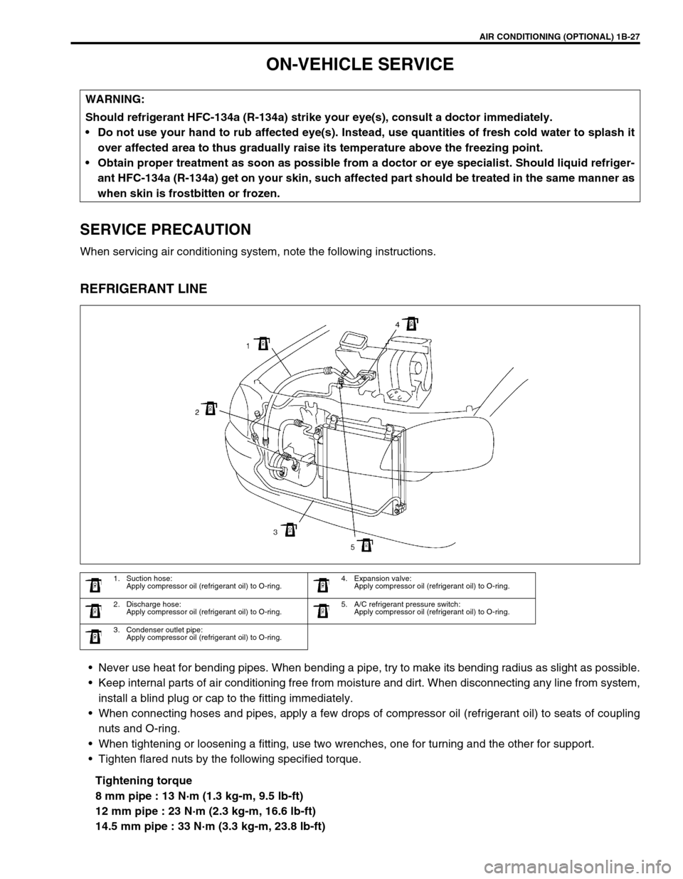
REFRIGERANT LINE
Never use heat for bending pipes. When bending a pipe, try to make its bending radius as slight as possible.
Keep internal parts of air conditioning free from moisture and dirt. When disconnecting any line from system,
install a blind plug or cap to the fitting immediately.
When connecting hoses and pipes, apply a few drops of compressor oil (refrigerant oil) to seats of coupling
nuts and O-ring.
When tightening or loosening a fitting, use two wrenches, one for turning and the other for support.
Tighten flared nuts by the following specified torque.
Tightening torque
8 mm pipe : 13 N·m (1.3 kg-m, 9.5 lb-ft)
12 mm pipe : 23 N·m (2.3 kg-m, 16.6 lb-ft)
14.5 mm pipe : 33 N·m (3.3 kg-m, 23.8 lb-ft) WARNING:
Should refrigerant HFC-134a (R-134a) strike your eye(s), consult a doctor immediately.
Do not use your hand to rub affected eye(s). Instead, use quantities of fresh cold water to splash it
over affected area to thus gradually raise its temperature above the freezing point.
Obtain proper treatment as soon as possible from a doctor or eye specialist. Should liquid refriger-
ant HFC-134a (R-134a) get on your skin, such affected part should be treated in the same manner as
when skin is frostbitten or frozen.
1. Suction hose:
Apply compressor oil (refrigerant oil) to O-ring.4. Expansion valve:
Apply compressor oil (refrigerant oil) to O-ring.
2. Discharge hose:
Apply compressor oil (refrigerant oil) to O-ring.5. A/C refrigerant pressure switch:
Apply compressor oil (refrigerant oil) to O-ring.
3. Condenser outlet pipe:
Apply compressor oil (refrigerant oil) to O-ring.
Page 93 of 698
1B-28 AIR CONDITIONING (OPTIONAL)
Route drain hose so that drained water does not make any contact to vehicle components.
If pipes or hoses are replaced, replenish specified amount of compressor oil to compressor suction side by
referring to “REPLENISHING COMPRESSOR OIL” in this section.
HANDLING REFRIGERANT HFC-134a (R-134a)
Always wear goggles to protect your eyes.
Avoid you direct contact to liquid refrigerant.
Do not heat refrigerant container higher than 40°C (104°F).
Do not discharge refrigerant into atmosphere.
Do not allow liquid refrigerant to touch bright metals. Refrigerant combined with moisture is corrosive and
will tarnish surfaces of bright metals including chrome.
REFRIGERANT RECOVERY
When discharging refrigerant out of A/C system, always recover it by using refrigerant recovery and recycling
equipment. Discharging refrigerant HFC-134a (R-134a) into atmosphere would cause adverse effect to environ-
ments.
REFRIGERANT CHARGE
After perform replenishing compressor oil and evacuating, charge a proper amount of refrigerant to A/C system
referring to “CHARGING” in this section.
CONDENSER ASSEMBLY
INSPECTION
Check the following.
Clog of condenser fins.
If, any clogs are found, condenser fins should be washed
with water, and should be dried with compressed air.
Condenser fins for leakage and breakage.
If any defects are found, repair or replace condenser.
Condenser fittings for leakage.
If any defects are found, repair or replace condenser. CAUTION:
Do not perform an additional refrigerant charging to A/C system. This cause it to overcharge.
CAUTION:
Be careful not to damage condenser fins. If condenser fin
is bent, straighten it by using flat head screwdriver or
pair of pliers.
Page 94 of 698
AIR CONDITIONING (OPTIONAL) 1B-29
REMOVAL
1) Disconnect negative (–) cable at battery.
2) Recover refrigerant from A/C system by referring to
“RECOVERY” in this section.
3) Remove front bumper referring to “FRONT BUMPER” in
Section 8.
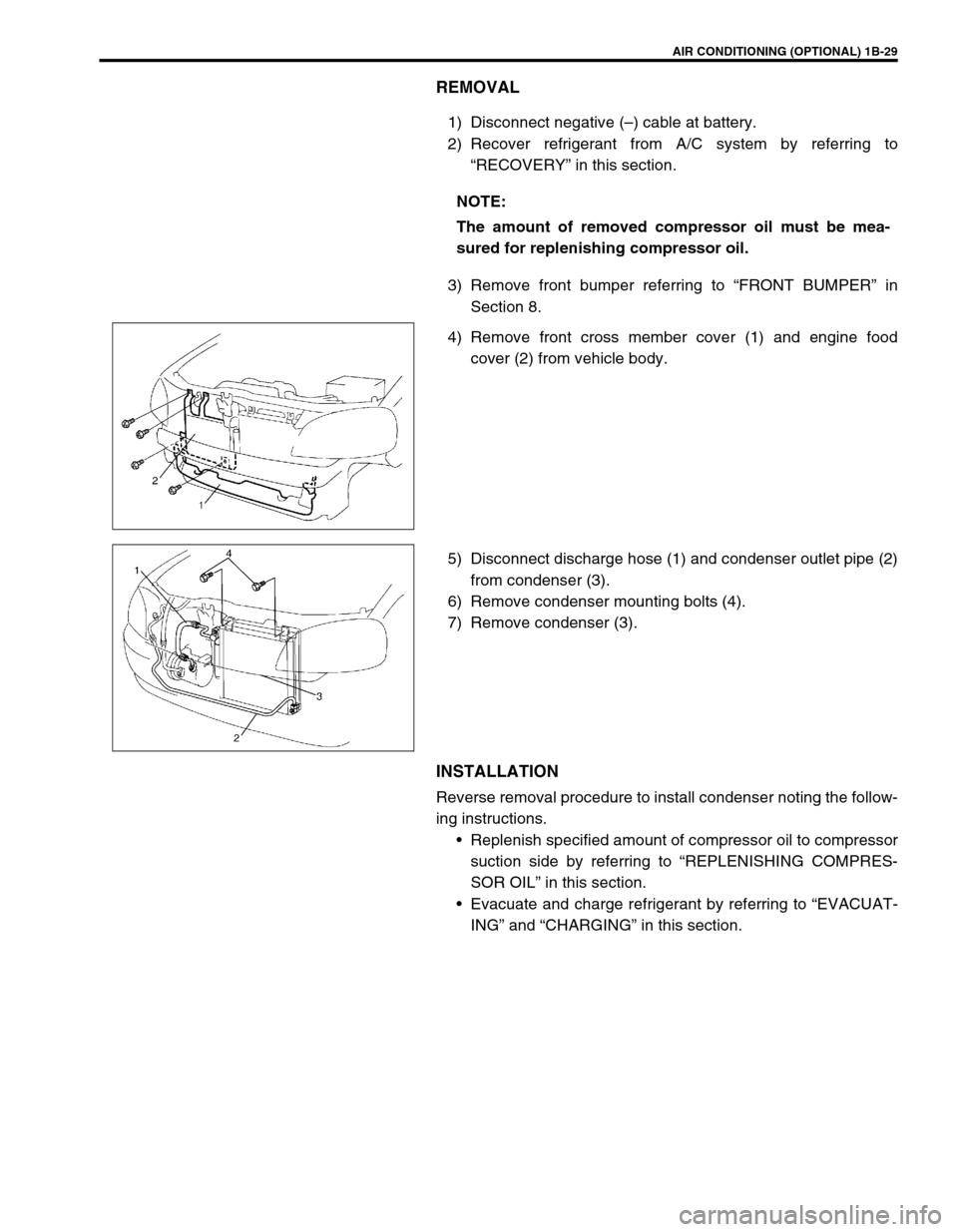
4) Remove front cross member cover (1) and engine food
cover (2) from vehicle body.
5) Disconnect discharge hose (1) and condenser outlet pipe (2)
from condenser (3).
6) Remove condenser mounting bolts (4).
7) Remove condenser (3).
INSTALLATION
Reverse removal procedure to install condenser noting the follow-
ing instructions.
Replenish specified amount of compressor oil to compressor
suction side by referring to “REPLENISHING COMPRES-
SOR OIL” in this section.
Evacuate and charge refrigerant by referring to “EVACUAT-
ING” and “CHARGING” in this section. NOTE:
The amount of removed compressor oil must be mea-
sured for replenishing compressor oil.