oil SUZUKI SWIFT 2000 1.G RG413 Service Repair Manual
[x] Cancel search | Manufacturer: SUZUKI, Model Year: 2000, Model line: SWIFT, Model: SUZUKI SWIFT 2000 1.GPages: 698, PDF Size: 16.01 MB
Page 179 of 698
3C-6 STEERING WHEEL AND COLUMN
STEERING WHEEL
REMOVAL
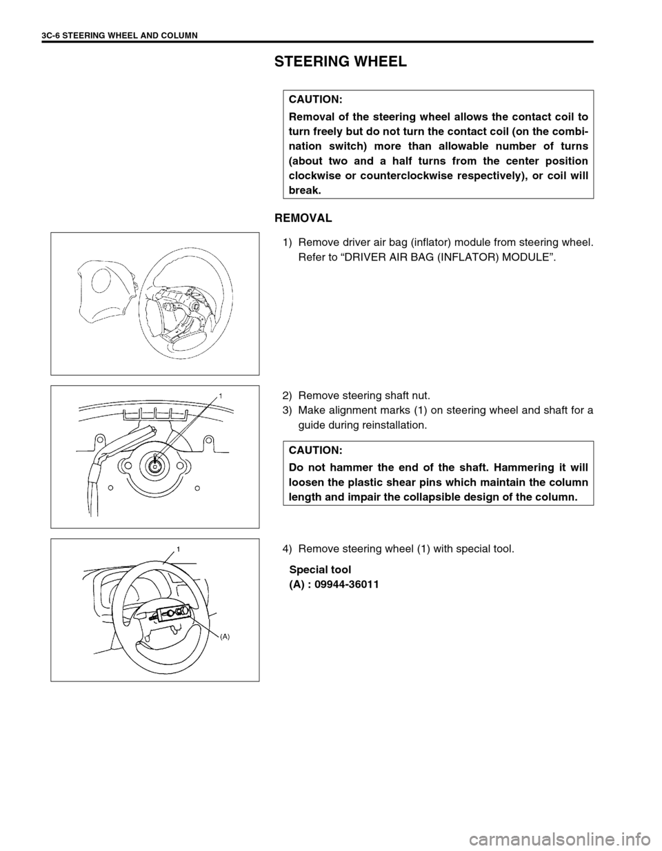
1) Remove driver air bag (inflator) module from steering wheel.
Refer to “DRIVER AIR BAG (INFLATOR) MODULE”.
2) Remove steering shaft nut.
3) Make alignment marks (1) on steering wheel and shaft for a
guide during reinstallation.
4) Remove steering wheel (1) with special tool.
Special tool
(A) : 09944-36011 CAUTION:
Removal of the steering wheel allows the contact coil to
turn freely but do not turn the contact coil (on the combi-
nation switch) more than allowable number of turns
(about two and a half turns from the center position
clockwise or counterclockwise respectively), or coil will
break.
CAUTION:
Do not hammer the end of the shaft. Hammering it will
loosen the plastic shear pins which maintain the column
length and impair the collapsible design of the column.
Page 180 of 698
STEERING WHEEL AND COLUMN 3C-7
INSTALLATION
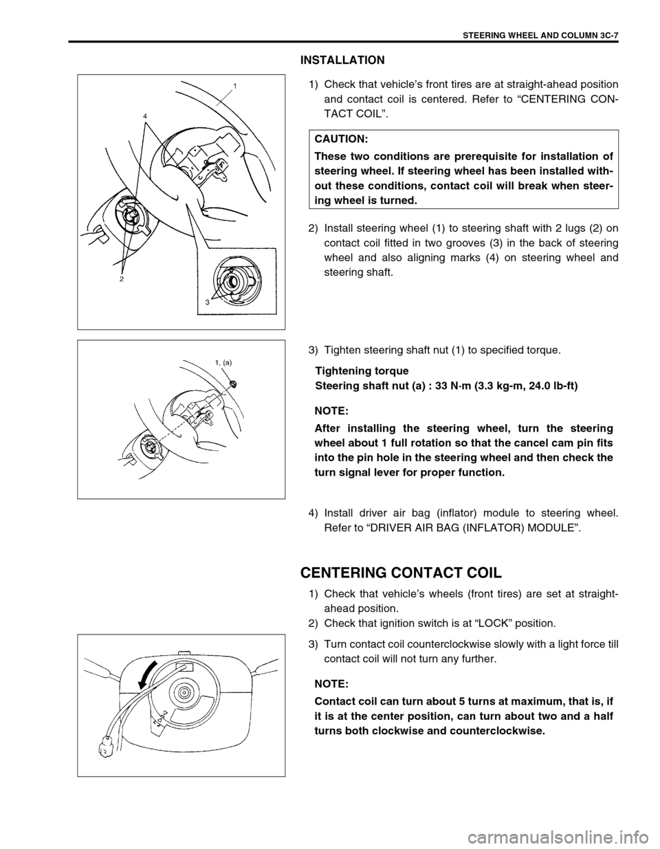
1) Check that vehicle’s front tires are at straight-ahead position
and contact coil is centered. Refer to “CENTERING CON-
TACT COIL”.
2) Install steering wheel (1) to steering shaft with 2 lugs (2) on
contact coil fitted in two grooves (3) in the back of steering
wheel and also aligning marks (4) on steering wheel and
steering shaft.
3) Tighten steering shaft nut (1) to specified torque.
Tightening torque
Steering shaft nut (a) : 33 N·m (3.3 kg-m, 24.0 lb-ft)
4) Install driver air bag (inflator) module to steering wheel.
Refer to “DRIVER AIR BAG (INFLATOR) MODULE”.
CENTERING CONTACT COIL
1) Check that vehicle’s wheels (front tires) are set at straight-
ahead position.
2) Check that ignition switch is at “LOCK” position.
3) Turn contact coil counterclockwise slowly with a light force till
contact coil will not turn any further. CAUTION:
These two conditions are prerequisite for installation of
steering wheel. If steering wheel has been installed with-
out these conditions, contact coil will break when steer-
ing wheel is turned.
NOTE:
After installing the steering wheel, turn the steering
wheel about 1 full rotation so that the cancel cam pin fits
into the pin hole in the steering wheel and then check the
turn signal lever for proper function.
NOTE:
Contact coil can turn about 5 turns at maximum, that is, if
it is at the center position, can turn about two and a half
turns both clockwise and counterclockwise.
Page 181 of 698
3C-8 STEERING WHEEL AND COLUMN
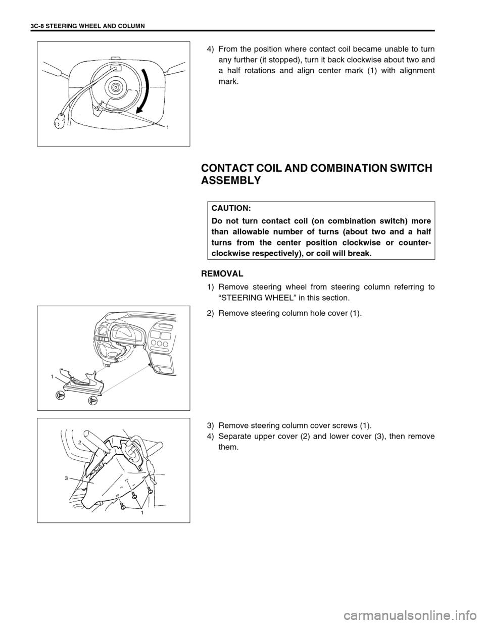
4) From the position where contact coil became unable to turn
any further (it stopped), turn it back clockwise about two and
a half rotations and align center mark (1) with alignment
mark.
CONTACT COIL AND COMBINATION SWITCH
ASSEMBLY
REMOVAL
1) Remove steering wheel from steering column referring to
“STEERING WHEEL” in this section.
2) Remove steering column hole cover (1).
3) Remove steering column cover screws (1).
4) Separate upper cover (2) and lower cover (3), then remove
them.
CAUTION:
Do not turn contact coil (on combination switch) more
than allowable number of turns (about two and a half
turns from the center position clockwise or counter-
clockwise respectively), or coil will break.
1
Page 182 of 698
STEERING WHEEL AND COLUMN 3C-9
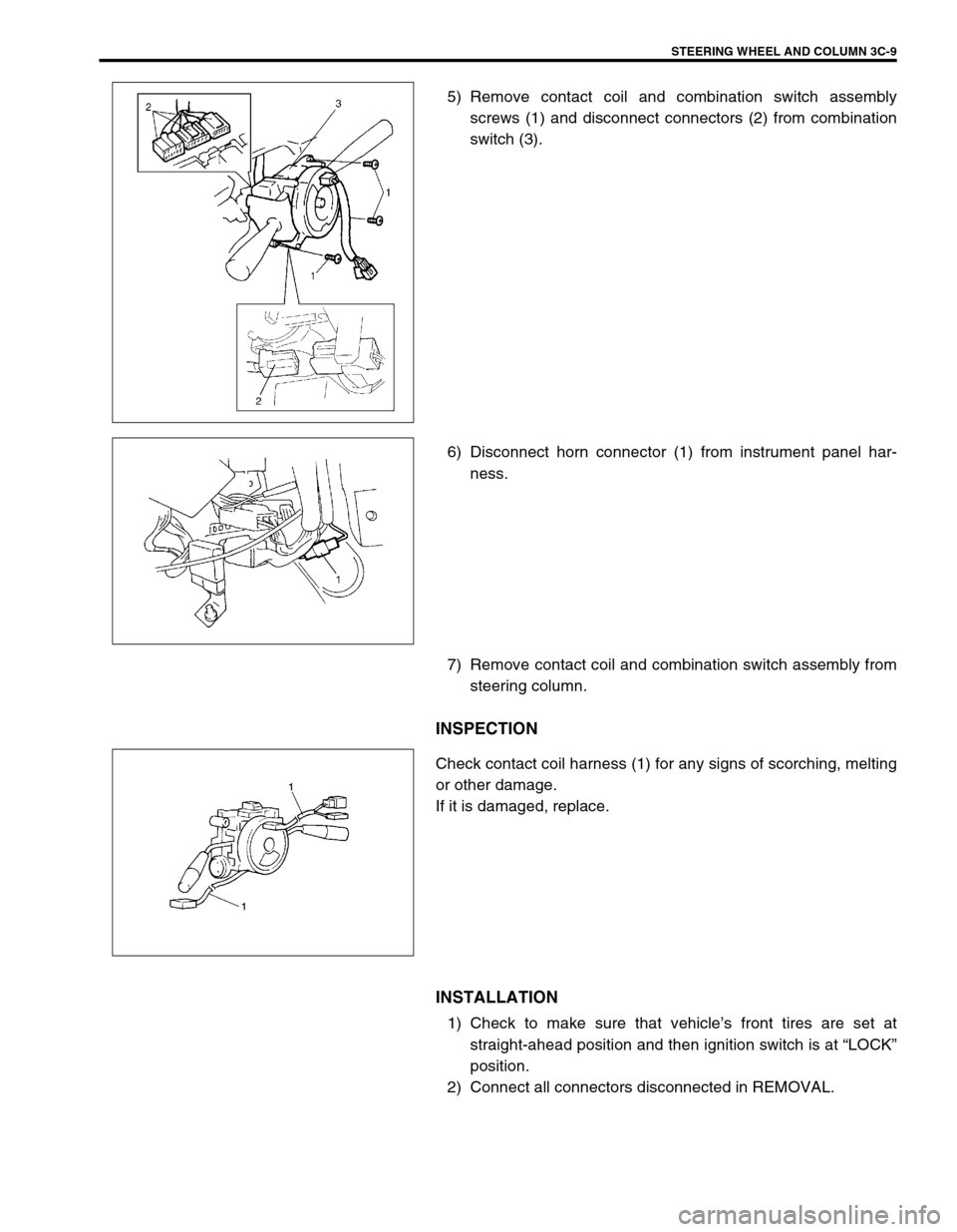
5) Remove contact coil and combination switch assembly
screws (1) and disconnect connectors (2) from combination
switch (3).
6) Disconnect horn connector (1) from instrument panel har-
ness.
7) Remove contact coil and combination switch assembly from
steering column.
INSPECTION
Check contact coil harness (1) for any signs of scorching, melting
or other damage.
If it is damaged, replace.
INSTALLATION
1) Check to make sure that vehicle’s front tires are set at
straight-ahead position and then ignition switch is at “LOCK”
position.
2) Connect all connectors disconnected in REMOVAL.
Page 183 of 698
3C-10 STEERING WHEEL AND COLUMN
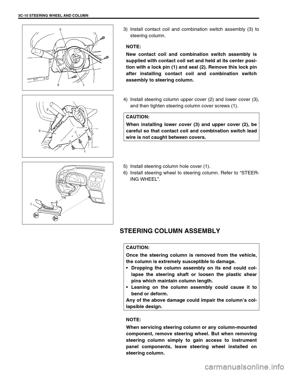
3) Install contact coil and combination switch assembly (3) to
steering column.
4) Install steering column upper cover (2) and lower cover (3),
and then tighten steering column cover screws (1).
5) Install steering column hole cover (1).
6) Install steering wheel to steering column. Refer to “STEER-
ING WHEEL”.
STEERING COLUMN ASSEMBLY
NOTE:
New contact coil and combination switch assembly is
supplied with contact coil set and held at its center posi-
tion with a lock pin (1) and seal (2). Remove this lock pin
after installing contact coil and combination switch
assembly to steering column.
CAUTION:
When installing lower cover (3) and upper cover (2), be
careful so that contact coil and combination switch lead
wire is not caught between covers.
1
CAUTION:
Once the steering column is removed from the vehicle,
the column is extremely susceptible to damage.
Dropping the column assembly on its end could col-
lapse the steering shaft or loosen the plastic shear
pins which maintain column length.
Leaning on the column assembly could cause it to
bend or deform.
Any of the above damage could impair the column’s col-
lapsible design.
NOTE:
When servicing steering column or any column-mounted
component, remove steering wheel. But when removing
steering column simply to gain access to instrument
panel components, leave steering wheel installed on
steering column.
Page 184 of 698
STEERING WHEEL AND COLUMN 3C-11
REMOVAL
1) Disconnect negative cable at battery.
2) Disable air bag system. Refer to “DISABLING AIR BAG
SYSTEM” under “SERVICE PRECAUTIONS” in Section
10B.
3) If it is necessary to remove steering wheel and contact coil
and combination switch assembly, remove them, referring to
“STEERING WHEEL” and “CONTACT COIL AND COMBI-
NATION SWITCH ASSEMBLY”.
If it is not necessary to remove steering wheel and contact
coil and combination switch assembly, perform the following
procedure.
a) Turn steering wheel so that vehicle’s front tires are at
straight-ahead position.
b) Turn ignition switch to “LOCK” position and remove key.
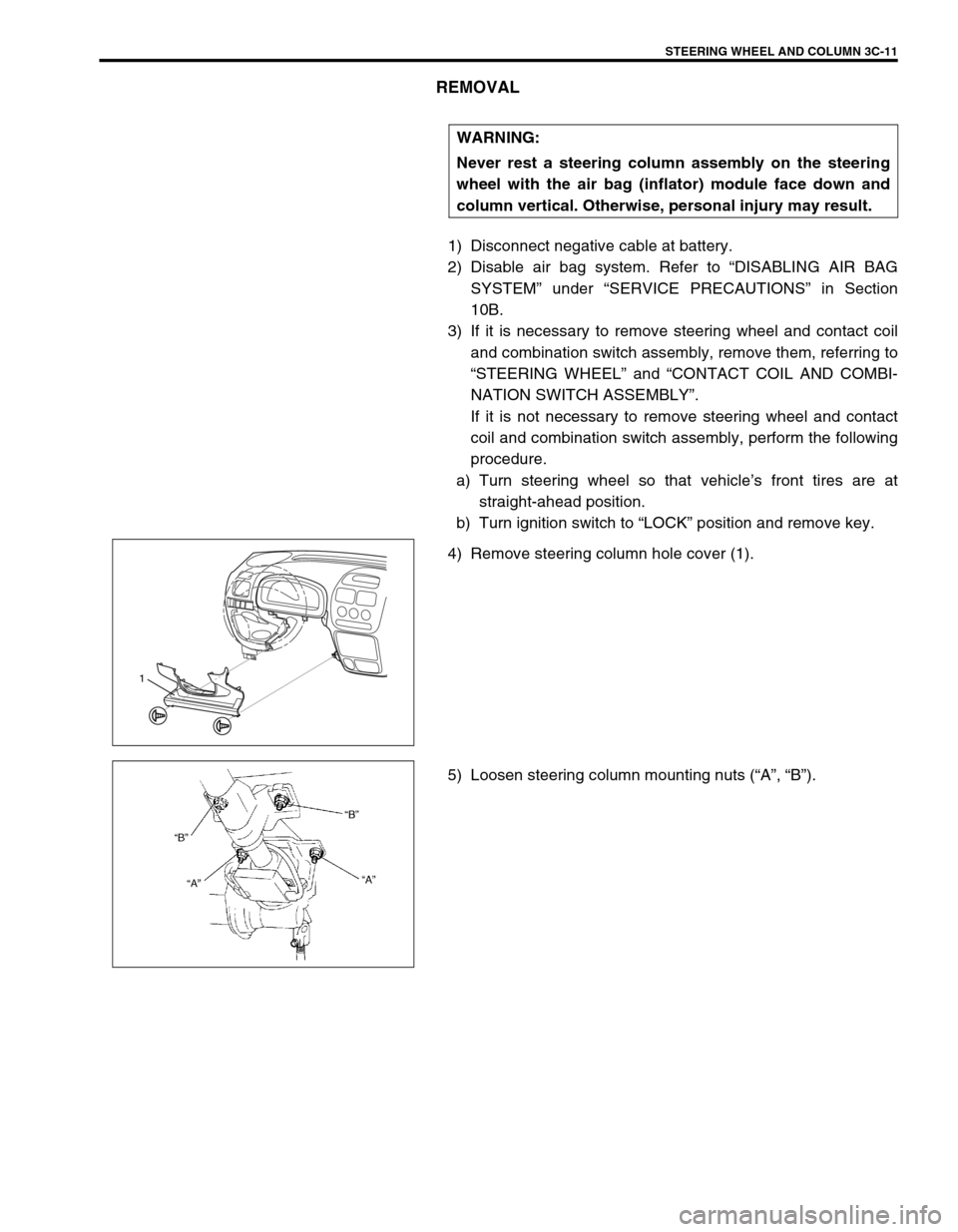
4) Remove steering column hole cover (1).
5) Loosen steering column mounting nuts (“A”, “B”). WARNING:
Never rest a steering column assembly on the steering
wheel with the air bag (inflator) module face down and
column vertical. Otherwise, personal injury may result.
1
Page 188 of 698
STEERING WHEEL AND COLUMN 3C-15
5) If contact coil and combination switch assembly is removed,
install it.
Refer to “CONTACT COIL AND COMBINATION SWITCH
ASSEMBLY”.
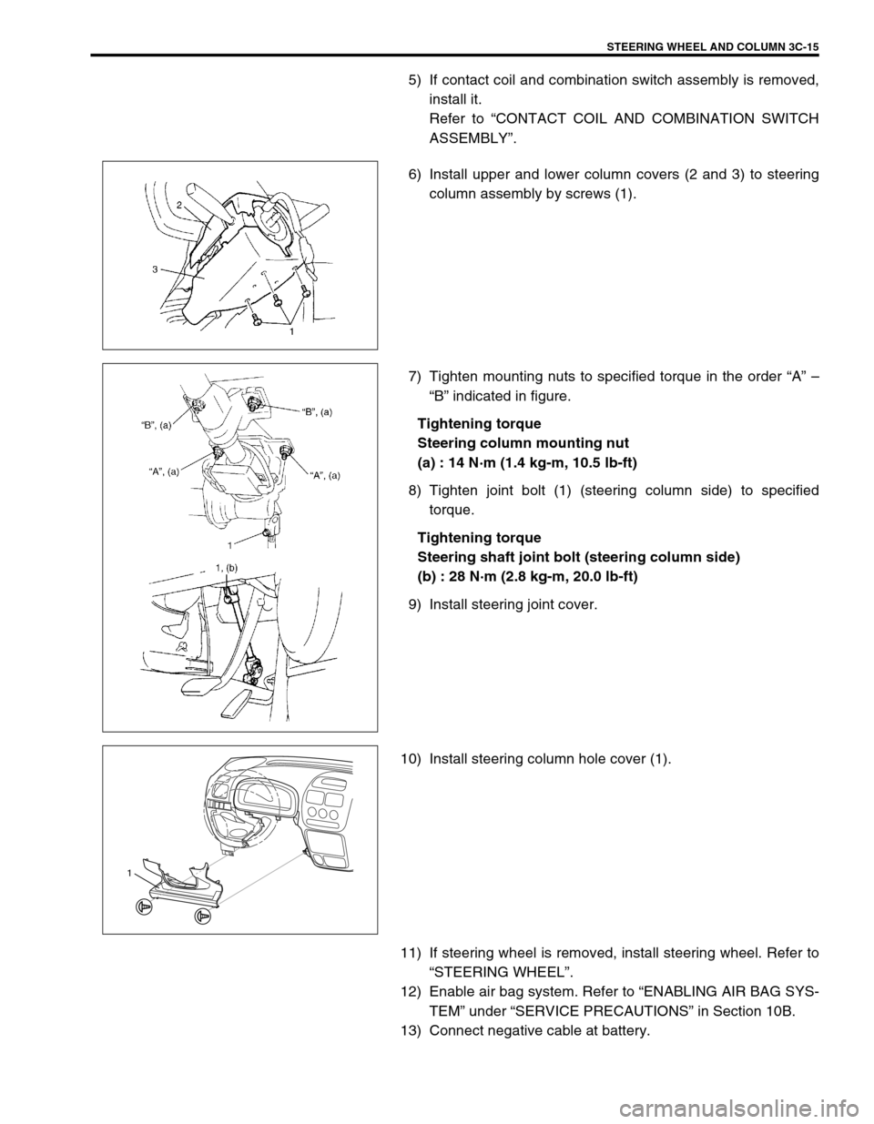
6) Install upper and lower column covers (2 and 3) to steering
column assembly by screws (1).
7) Tighten mounting nuts to specified torque in the order “A” –
“B” indicated in figure.
Tightening torque
Steering column mounting nut
(a) : 14 N·m (1.4 kg-m, 10.5 lb-ft)
8) Tighten joint bolt (1) (steering column side) to specified
torque.
Tightening torque
Steering shaft joint bolt (steering column side)
(b) : 28 N·m (2.8 kg-m, 20.0 lb-ft)
9) Install steering joint cover.
10) Install steering column hole cover (1).
11) If steering wheel is removed, install steering wheel. Refer to
“STEERING WHEEL”.
12) Enable air bag system. Refer to “ENABLING AIR BAG SYS-
TEM” under “SERVICE PRECAUTIONS” in Section 10B.
13) Connect negative cable at battery.
1
Page 190 of 698
STEERING WHEEL AND COLUMN 3C-17
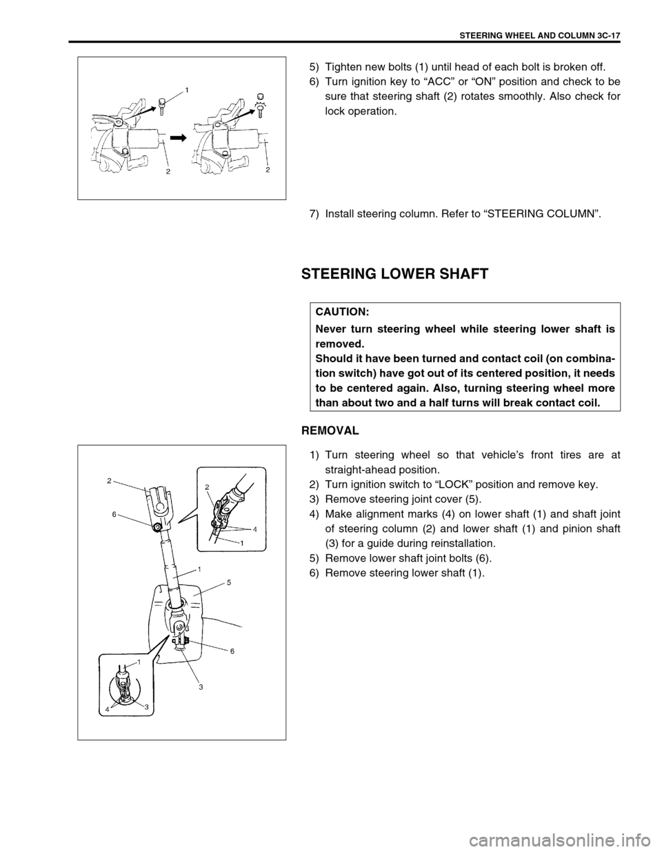
5) Tighten new bolts (1) until head of each bolt is broken off.
6) Turn ignition key to “ACC” or “ON” position and check to be
sure that steering shaft (2) rotates smoothly. Also check for
lock operation.
7) Install steering column. Refer to “STEERING COLUMN”.
STEERING LOWER SHAFT
REMOVAL
1) Turn steering wheel so that vehicle’s front tires are at
straight-ahead position.
2) Turn ignition switch to “LOCK” position and remove key.
3) Remove steering joint cover (5).
4) Make alignment marks (4) on lower shaft (1) and shaft joint
of steering column (2) and lower shaft (1) and pinion shaft
(3) for a guide during reinstallation.
5) Remove lower shaft joint bolts (6).
6) Remove steering lower shaft (1).
CAUTION:
Never turn steering wheel while steering lower shaft is
removed.
Should it have been turned and contact coil (on combina-
tion switch) have got out of its centered position, it needs
to be centered again. Also, turning steering wheel more
than about two and a half turns will break contact coil.
Page 196 of 698
FRONT SUSPENSION 3D-3
DIAGNOSIS
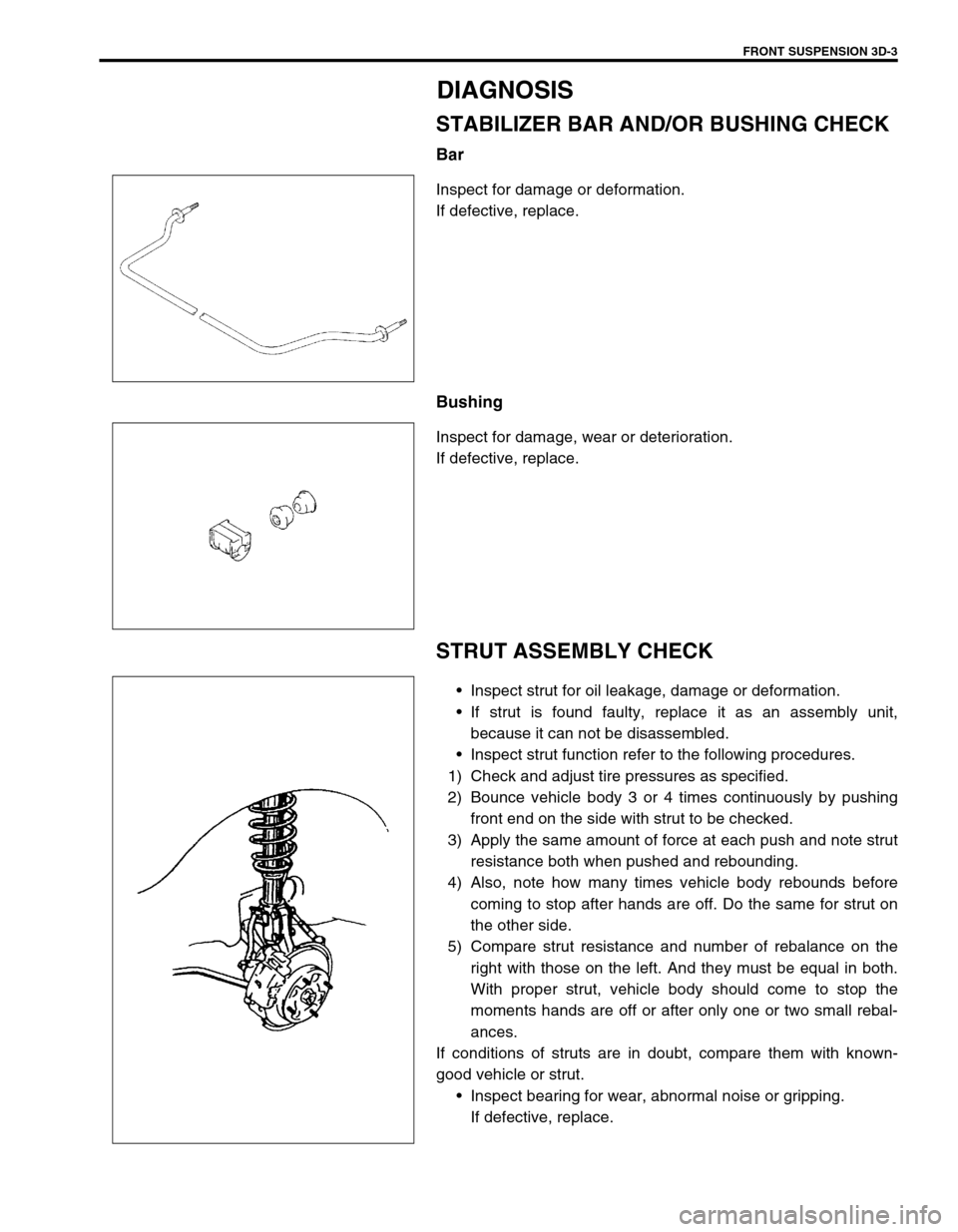
STABILIZER BAR AND/OR BUSHING CHECK
Bar
Inspect for damage or deformation.
If defective, replace.
Bushing
Inspect for damage, wear or deterioration.
If defective, replace.
STRUT ASSEMBLY CHECK
Inspect strut for oil leakage, damage or deformation.
If strut is found faulty, replace it as an assembly unit,
because it can not be disassembled.
Inspect strut function refer to the following procedures.
1) Check and adjust tire pressures as specified.
2) Bounce vehicle body 3 or 4 times continuously by pushing
front end on the side with strut to be checked.
3) Apply the same amount of force at each push and note strut
resistance both when pushed and rebounding.
4) Also, note how many times vehicle body rebounds before
coming to stop after hands are off. Do the same for strut on
the other side.
5) Compare strut resistance and number of rebalance on the
right with those on the left. And they must be equal in both.
With proper strut, vehicle body should come to stop the
moments hands are off or after only one or two small rebal-
ances.
If conditions of struts are in doubt, compare them with known-
good vehicle or strut.
Inspect bearing for wear, abnormal noise or gripping.
If defective, replace.
Page 199 of 698
3D-6 FRONT SUSPENSION
ON-VEHICLE SERVICE
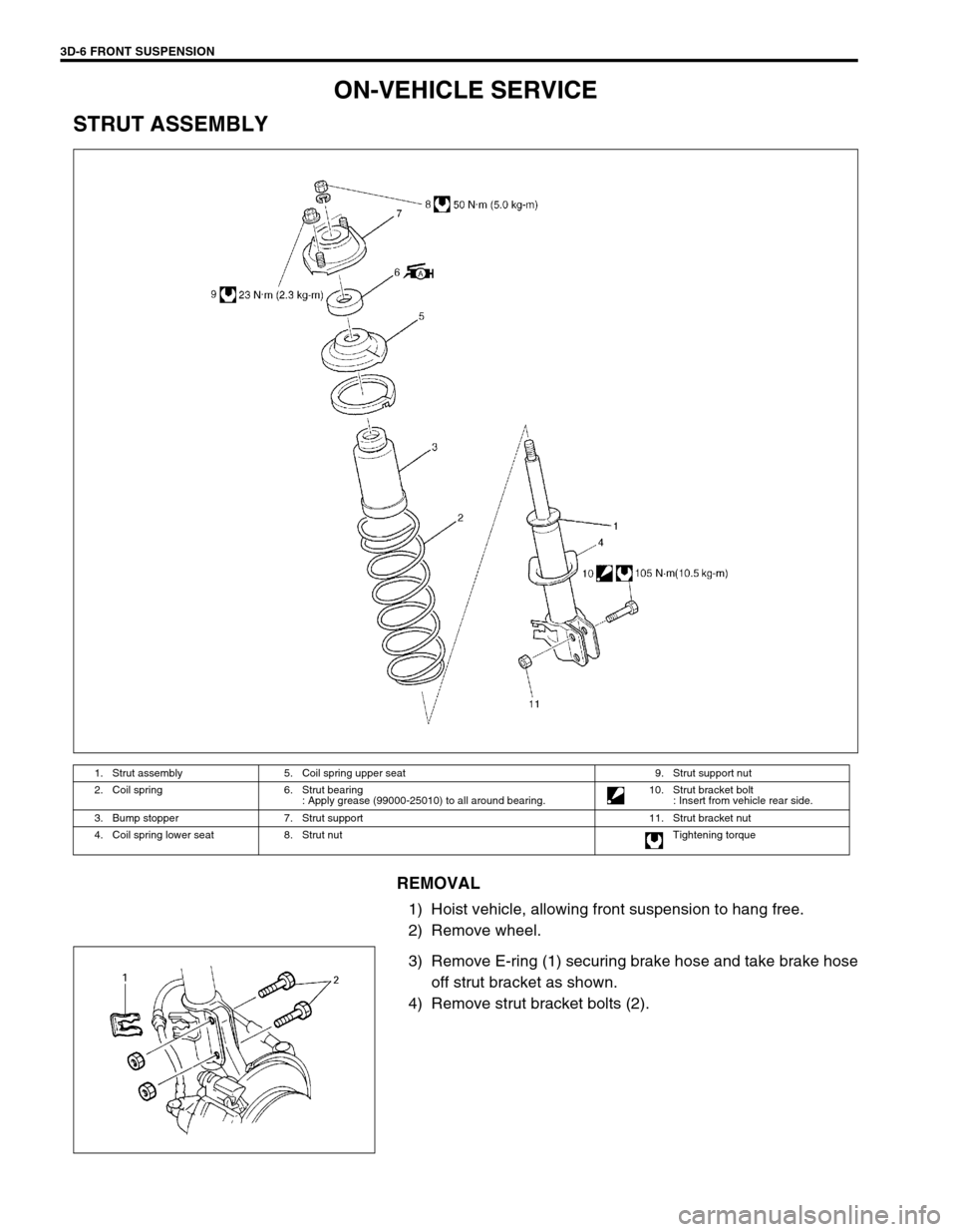
STRUT ASSEMBLY
REMOVAL
1) Hoist vehicle, allowing front suspension to hang free.
2) Remove wheel.
3) Remove E-ring (1) securing brake hose and take brake hose
off strut bracket as shown.
4) Remove strut bracket bolts (2).
1. Strut assembly 5. Coil spring upper seat 9. Strut support nut
2. Coil spring 6. Strut bearing
: Apply grease (99000-25010) to all around bearing.10. Strut bracket bolt
: Insert from vehicle rear side.
3. Bump stopper 7. Strut support 11. Strut bracket nut
4. Coil spring lower seat 8. Strut nut Tightening torque