oil level SUZUKI SWIFT 2000 1.G RG413 Service User Guide
[x] Cancel search | Manufacturer: SUZUKI, Model Year: 2000, Model line: SWIFT, Model: SUZUKI SWIFT 2000 1.GPages: 698, PDF Size: 16.01 MB
Page 322 of 698
BRAKES 5-49
INSTALLATION
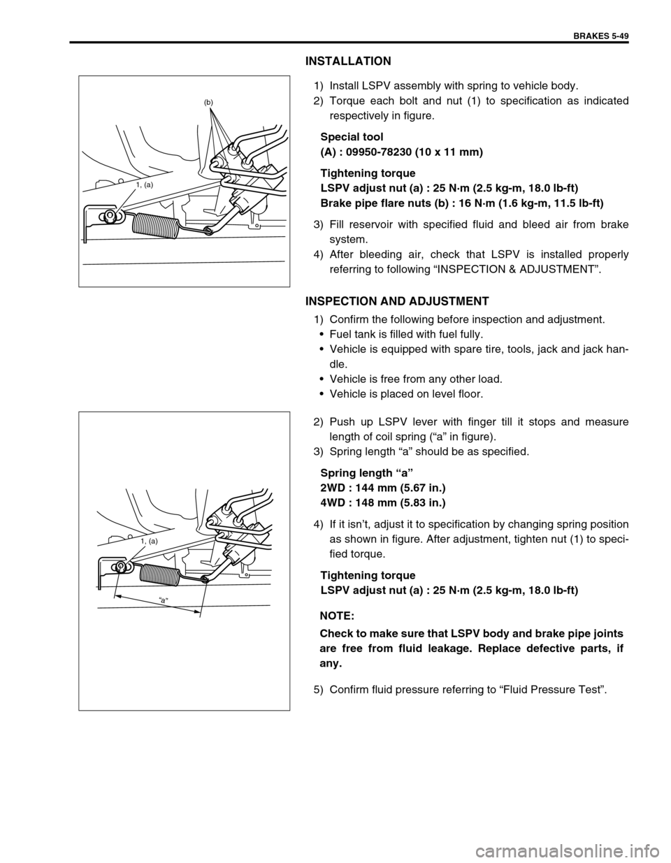
1) Install LSPV assembly with spring to vehicle body.
2) Torque each bolt and nut (1) to specification as indicated
respectively in figure.
Special tool
(A) : 09950-78230 (10 x 11 mm)
Tightening torque
LSPV adjust nut (a) : 25 N·m (2.5 kg-m, 18.0 lb-ft)
Brake pipe flare nuts (b) : 16 N·m (1.6 kg-m, 11.5 lb-ft)
3) Fill reservoir with specified fluid and bleed air from brake
system.
4) After bleeding air, check that LSPV is installed properly
referring to following “INSPECTION & ADJUSTMENT”.
INSPECTION AND ADJUSTMENT
1) Confirm the following before inspection and adjustment.
Fuel tank is filled with fuel fully.
Vehicle is equipped with spare tire, tools, jack and jack han-
dle.
Vehicle is free from any other load.
Vehicle is placed on level floor.
2) Push up LSPV lever with finger till it stops and measure
length of coil spring (“a” in figure).
3) Spring length “a” should be as specified.
Spring length “a”
2WD : 144 mm (5.67 in.)
4WD : 148 mm (5.83 in.)
4) If it isn’t, adjust it to specification by changing spring position
as shown in figure. After adjustment, tighten nut (1) to speci-
fied torque.
Tightening torque
LSPV adjust nut (a) : 25 N·m (2.5 kg-m, 18.0 lb-ft)
5) Confirm fluid pressure referring to “Fluid Pressure Test”.
1, (a)
(b)
NOTE:
Check to make sure that LSPV body and brake pipe joints
are free from fluid leakage. Replace defective parts, if
any.
1, (a)
“a”
Page 391 of 698
6-22 ENGINE GENERAL INFORMATION AND DIAGNOSIS
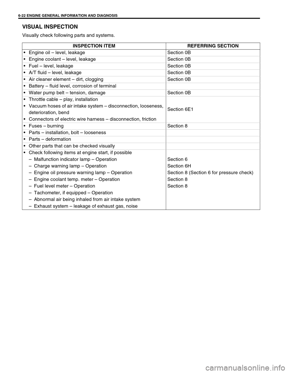
VISUAL INSPECTION
Visually check following parts and systems.
INSPECTION ITEM REFERRING SECTION
Engine oil – level, leakage Section 0B
Engine coolant – level, leakage Section 0B
Fuel – level, leakage Section 0B
A/T fluid – level, leakage Section 0B
Air cleaner element – dirt, clogging Section 0B
Battery – fluid level, corrosion of terminal
Water pump belt – tension, damage Section 0B
Throttle cable – play, installation
Section 6E1 Vacuum hoses of air intake system – disconnection, looseness,
deterioration, bend
Connectors of electric wire harness – disconnection, friction
Fuses – burning Section 8
Parts – installation, bolt – looseness
Parts – deformation
Other parts that can be checked visually
Check following items at engine start, if possible
–Malfunction indicator lamp – Operation Section 6
–Charge warning lamp – Operation Section 6H
–Engine oil pressure warning lamp – Operation Section 8 (Section 6 for pressure check)
–Engine coolant temp. meter – Operation Section 8
–Fuel level meter – Operation Section 8
–Tachometer, if equipped – Operation
–Abnormal air being inhaled from air intake system
–Exhaust system – leakage of exhaust gas, noise
Page 508 of 698

ENGINE MECHANICAL (M13 ENGINE) 6A1-7
4) Connect special tool (Vacuum gauge) to intake manifold.
Special tool
(A) : 09915-67310
5) Run engine at specified idle speed and read vacuum gauge.
Vacuum should be within specification.
Vacuum specification (at sea level)
: 59 – 73 kPa (45 – 55 cmHg, 17.7 – 21.6 inHg)
at specified idle speed
6) After checking, disconnect special tool (Vacuum gauge) from
intake manifold.
7) Install cap to intake manifold.
OIL PRESSURE CHECK
Oil level in oil pan
If oil level is low, add oil up to Full level mark (hole) on oil
level gauge.
Oil quality
If oil is discolored, or deteriorated, change it.
For particular oil to be used referring to the table in Section
0B.
Oil leaks
If leak is found, repair it.
1) Disconnect oil pressure switch coupler (1) and remove oil
pressure switch (2) from cylinder block.
NOTE:
Prior to checking oil pressure, check the following items.
1. Full level mark (hole)
2. Low level mark (hole)
Page 515 of 698
6A1-14 ENGINE MECHANICAL (M13 ENGINE)
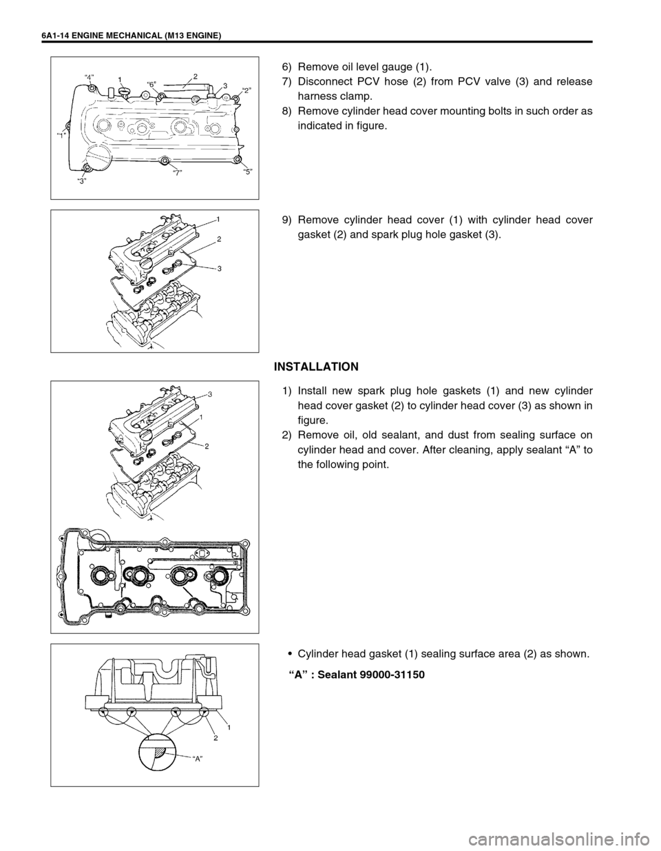
6) Remove oil level gauge (1).
7) Disconnect PCV hose (2) from PCV valve (3) and release
harness clamp.
8) Remove cylinder head cover mounting bolts in such order as
indicated in figure.
9) Remove cylinder head cover (1) with cylinder head cover
gasket (2) and spark plug hole gasket (3).
INSTALLATION
1) Install new spark plug hole gaskets (1) and new cylinder
head cover gasket (2) to cylinder head cover (3) as shown in
figure.
2) Remove oil, old sealant, and dust from sealing surface on
cylinder head and cover. After cleaning, apply sealant “A” to
the following point.
Cylinder head gasket (1) sealing surface area (2) as shown.
“A” : Sealant 99000-31150
Page 516 of 698
ENGINE MECHANICAL (M13 ENGINE) 6A1-15
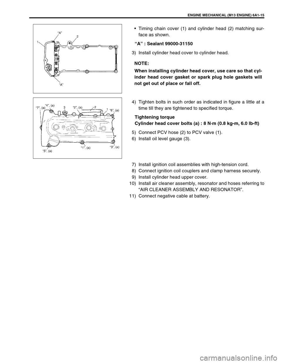
Timing chain cover (1) and cylinder head (2) matching sur-
face as shown.
“A” : Sealant 99000-31150
3) Install cylinder head cover to cylinder head.
4) Tighten bolts in such order as indicated in figure a little at a
time till they are tightened to specified torque.
Tightening torque
Cylinder head cover bolts (a) : 8 N·m (0.8 kg-m, 6.0 lb-ft)
5) Connect PCV hose (2) to PCV valve (1).
6) Install oil level gauge (3).
7) Install ignition coil assemblies with high-tension cord.
8) Connect ignition coil couplers and clamp harness securely.
9) Install cylinder head upper cover.
10) Install air cleaner assembly, resonator and hoses referring to
“AIR CLEANER ASSEMBLY AND RESONATOR”.
11) Connect negative cable at battery.NOTE:
When installing cylinder head cover, use care so that cyl-
inder head cover gasket or spark plug hole gaskets will
not get out of place or fall off.
Page 522 of 698
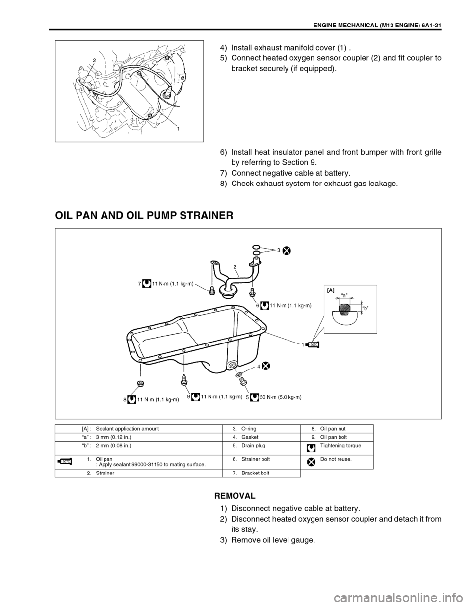
ENGINE MECHANICAL (M13 ENGINE) 6A1-21
4) Install exhaust manifold cover (1) .
5) Connect heated oxygen sensor coupler (2) and fit coupler to
bracket securely (if equipped).
6) Install heat insulator panel and front bumper with front grille
by referring to Section 9.
7) Connect negative cable at battery.
8) Check exhaust system for exhaust gas leakage.
OIL PAN AND OIL PUMP STRAINER
REMOVAL
1) Disconnect negative cable at battery.
2) Disconnect heated oxygen sensor coupler and detach it from
its stay.
3) Remove oil level gauge.
[A] : Sealant application amount 3. O-ring 8. Oil pan nut
“a” : 3 mm (0.12 in.) 4. Gasket 9. Oil pan bolt
“b” : 2 mm (0.08 in.) 5. Drain plug Tightening torque
1. Oil pan
: Apply sealant 99000-31150 to mating surface.6. Strainer bolt Do not reuse.
2. Strainer 7. Bracket bolt
Page 525 of 698
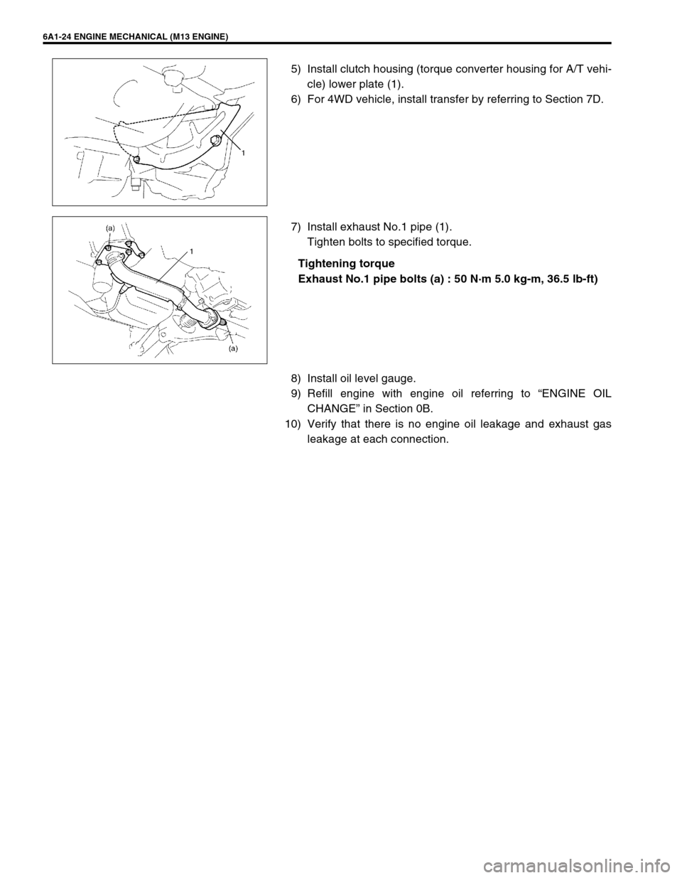
6A1-24 ENGINE MECHANICAL (M13 ENGINE)
5) Install clutch housing (torque converter housing for A/T vehi-
cle) lower plate (1).
6) For 4WD vehicle, install transfer by referring to Section 7D.
7) Install exhaust No.1 pipe (1).
Tighten bolts to specified torque.
Tightening torque
Exhaust No.1 pipe bolts (a) : 50 N·m 5.0 kg-m, 36.5 lb-ft)
8) Install oil level gauge.
9) Refill engine with engine oil referring to “ENGINE OIL
CHANGE” in Section 0B.
10) Verify that there is no engine oil leakage and exhaust gas
leakage at each connection.
Page 595 of 698
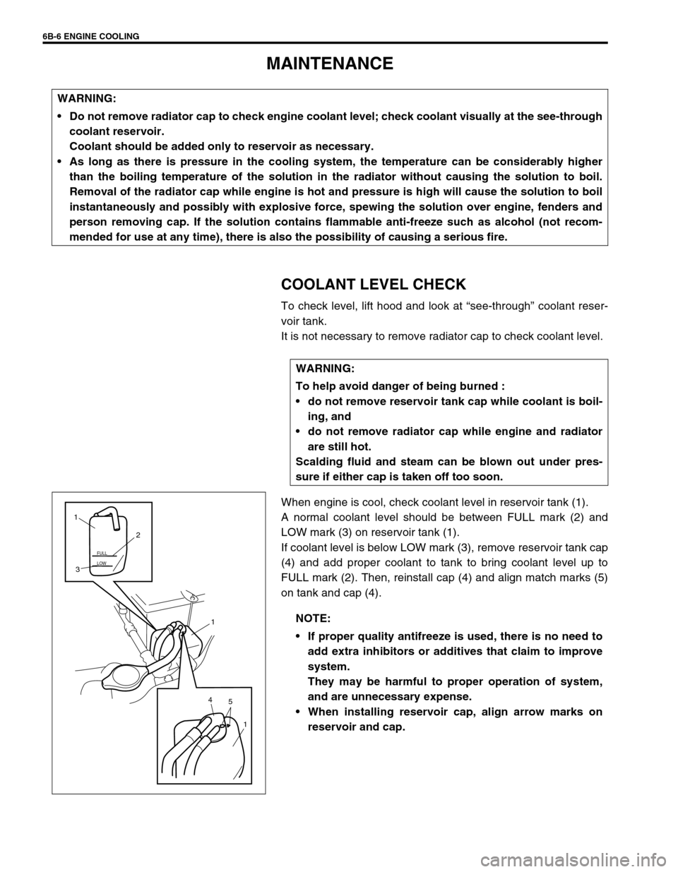
6B-6 ENGINE COOLING
MAINTENANCE
COOLANT LEVEL CHECK
To check level, lift hood and look at “see-through” coolant reser-
voir tank.
It is not necessary to remove radiator cap to check coolant level.
When engine is cool, check coolant level in reservoir tank (1).
A normal coolant level should be between FULL mark (2) and
LOW mark (3) on reservoir tank (1).
If coolant level is below LOW mark (3), remove reservoir tank cap
(4) and add proper coolant to tank to bring coolant level up to
FULL mark (2). Then, reinstall cap (4) and align match marks (5)
on tank and cap (4). WARNING:
Do not remove radiator cap to check engine coolant level; check coolant visually at the see-through
coolant reservoir.
Coolant should be added only to reservoir as necessary.
As long as there is pressure in the cooling system, the temperature can be considerably higher
than the boiling temperature of the solution in the radiator without causing the solution to boil.
Removal of the radiator cap while engine is hot and pressure is high will cause the solution to boil
instantaneously and possibly with explosive force, spewing the solution over engine, fenders and
person removing cap. If the solution contains flammable anti-freeze such as alcohol (not recom-
mended for use at any time), there is also the possibility of causing a serious fire.
WARNING:
To help avoid danger of being burned :
do not remove reservoir tank cap while coolant is boil-
ing, and
do not remove radiator cap while engine and radiator
are still hot.
Scalding fluid and steam can be blown out under pres-
sure if either cap is taken off too soon.
NOTE:
If proper quality antifreeze is used, there is no need to
add extra inhibitors or additives that claim to improve
system.
They may be harmful to proper operation of system,
and are unnecessary expense.
When installing reservoir cap, align arrow marks on
reservoir and cap.
LOW FULL
5 41
1 32 1
Page 619 of 698
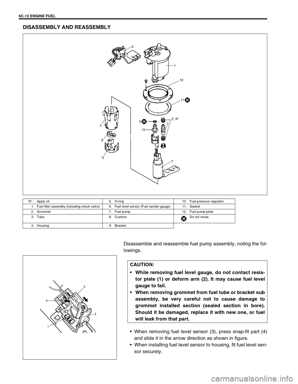
6C-12 ENGINE FUEL
DISASSEMBLY AND REASSEMBLY
Disassemble and reassemble fuel pump assembly, noting the fol-
lowings.
When removing fuel level sensor (3), press snap-fit part (4)
and slide it in the arrow direction as shown in figure.
When installing fuel level sensor to housing, fit fuel level sen-
sor securely.
“A” : Apply oil 5. O-ring 10. Fuel pressure regulator
1. Fuel filter assembly (including check valve) 6. Fuel level sensor (Fuel sender gauge) 11. Gasket
2. Grommet 7. Fuel pump 12. Fuel pump plate
3. Tube 8. Cushion Do not reuse.
4. Housing 9. Bracket
CAUTION:
While removing fuel level gauge, do not contact resis-
tor plate (1) or deform arm (2). It may cause fuel level
gauge to fail.
When removing grommet from fuel tube or bracket sub
assembly, be very careful not to cause damage to
grommet installed section (sealed section in bore).
Should it be damaged, replace it with new one, or fuel
will leak from that part.
Page 626 of 698
ENGINE AND EMISSION CONTROL SYSTEM 6E1-5
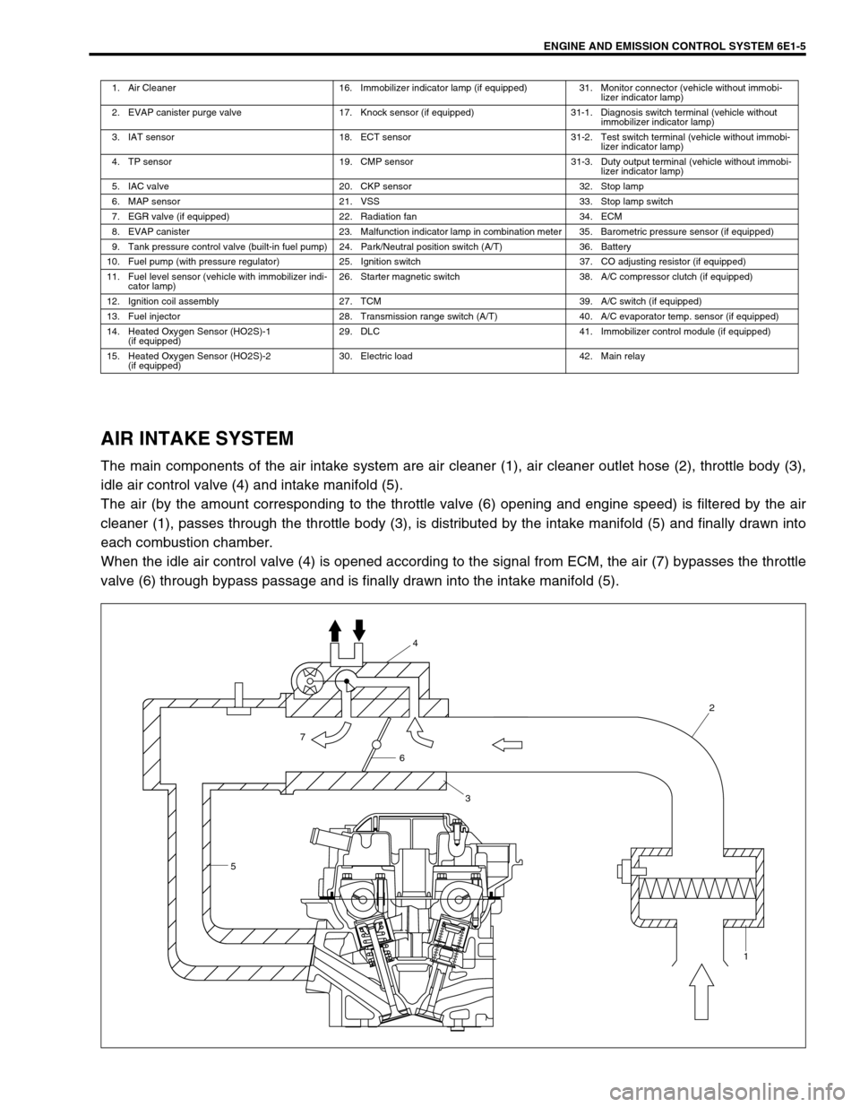
AIR INTAKE SYSTEM
The main components of the air intake system are air cleaner (1), air cleaner outlet hose (2), throttle body (3),
idle air control valve (4) and intake manifold (5).
The air (by the amount corresponding to the throttle valve (6) opening and engine speed) is filtered by the air
cleaner (1), passes through the throttle body (3), is distributed by the intake manifold (5) and finally drawn into
each combustion chamber.
When the idle air control valve (4) is opened according to the signal from ECM, the air (7) bypasses the throttle
valve (6) through bypass passage and is finally drawn into the intake manifold (5).
1. Air Cleaner 16. Immobilizer indicator lamp (if equipped) 31. Monitor connector (vehicle without immobi-
lizer indicator lamp)
2. EVAP canister purge valve 17. Knock sensor (if equipped) 31-1. Diagnosis switch terminal (vehicle without
immobilizer indicator lamp)
3. IAT sensor 18. ECT sensor 31-2. Test switch terminal (vehicle without immobi-
lizer indicator lamp)
4. TP sensor 19. CMP sensor 31-3. Duty output terminal (vehicle without immobi-
lizer indicator lamp)
5. IAC valve 20. CKP sensor 32. Stop lamp
6. MAP sensor 21. VSS 33. Stop lamp switch
7. EGR valve (if equipped) 22. Radiation fan 34. ECM
8. EVAP canister 23. Malfunction indicator lamp in combination meter 35. Barometric pressure sensor (if equipped)
9. Tank pressure control valve (built-in fuel pump) 24. Park/Neutral position switch (A/T) 36. Battery
10. Fuel pump (with pressure regulator) 25. Ignition switch 37. CO adjusting resistor (if equipped)
11. Fuel level sensor (vehicle with immobilizer indi-
cator lamp)26. Starter magnetic switch 38. A/C compressor clutch (if equipped)
12. Ignition coil assembly 27. TCM 39. A/C switch (if equipped)
13. Fuel injector 28. Transmission range switch (A/T) 40. A/C evaporator temp. sensor (if equipped)
14. Heated Oxygen Sensor (HO2S)-1
(if equipped)29. DLC 41. Immobilizer control module (if equipped)
15. Heated Oxygen Sensor (HO2S)-2
(if equipped)30. Electric load 42. Main relay
54
2
1
6
3
7