transmission oil SUZUKI SWIFT 2000 1.G RG413 Service User Guide
[x] Cancel search | Manufacturer: SUZUKI, Model Year: 2000, Model line: SWIFT, Model: SUZUKI SWIFT 2000 1.GPages: 698, PDF Size: 16.01 MB
Page 269 of 698
4A-16 FRONT DRIVE SHAFT
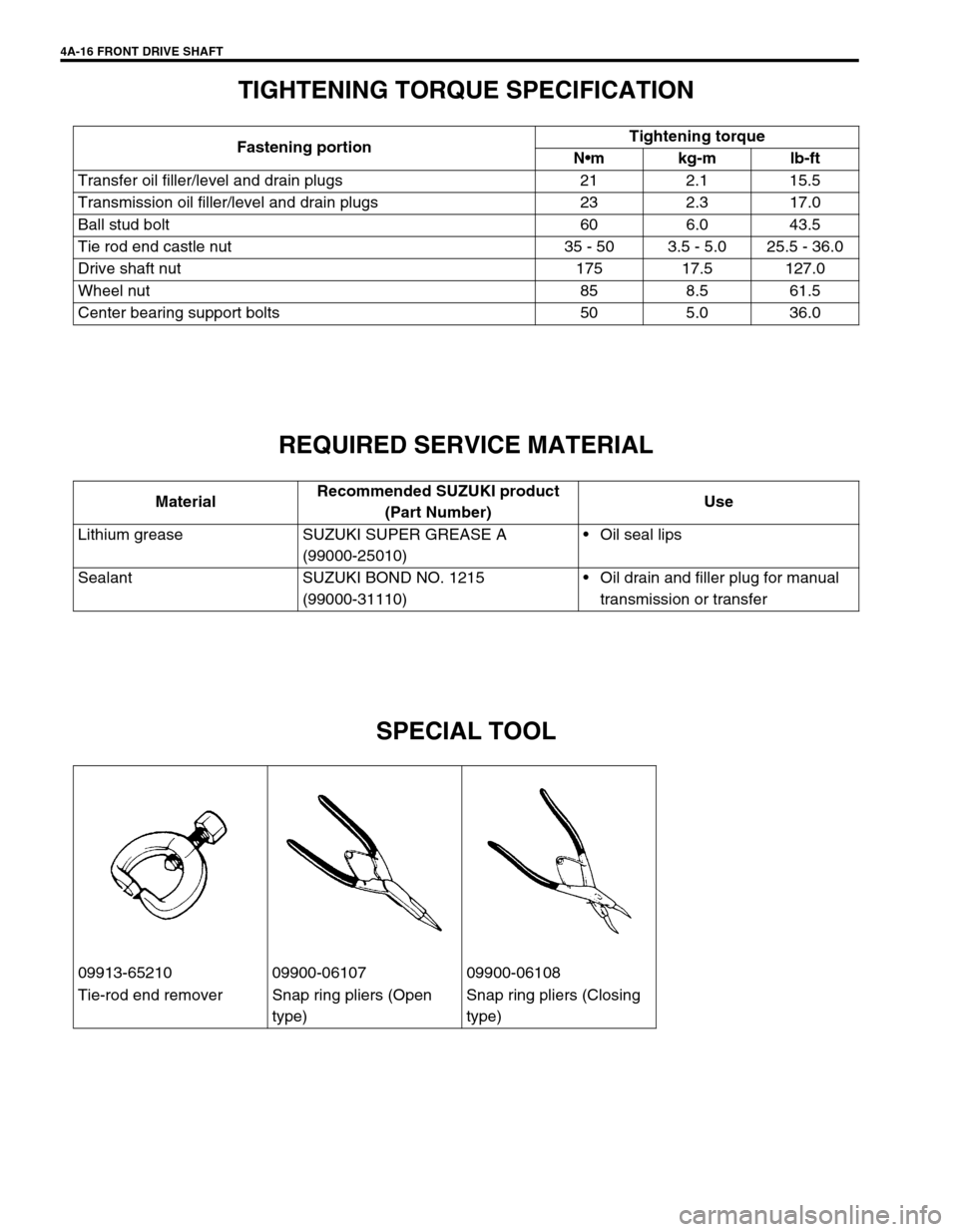
TIGHTENING TORQUE SPECIFICATION
REQUIRED SERVICE MATERIAL
SPECIAL TOOL
Fastening portionTightening torque
Nm kg-m lb-ft
Transfer oil filler/level and drain plugs 21 2.1 15.5
Transmission oil filler/level and drain plugs 23 2.3 17.0
Ball stud bolt 60 6.0 43.5
Tie rod end castle nut 35 - 50 3.5 - 5.0 25.5 - 36.0
Drive shaft nut 175 17.5 127.0
Wheel nut 85 8.5 61.5
Center bearing support bolts 50 5.0 36.0
MaterialRecommended SUZUKI product
(Part Number)Use
Lithium grease SUZUKI SUPER GREASE A
(99000-25010)Oil seal lips
Sealant SUZUKI BOND NO. 1215
(99000-31110)Oil drain and filler plug for manual
transmission or transfer
09913-65210 09900-06107 09900-06108
Tie-rod end remover Snap ring pliers (Open
type)Snap ring pliers (Closing
type)
Page 505 of 698

6A1-4 ENGINE MECHANICAL (M13 ENGINE)
DIAGNOSIS
DIAGNOSIS TABLE
Refer to “ENGINE MECHANICAL DIAGNOSIS TABLE” in Sec-
tion 6.
COMPRESSION CHECK
Check compression pressure on all 4 cylinders as follows:
1) Warm up engine to normal operating temperature.
2) Stop engine after warming up.
3) Remove air cleaner assembly (1), resonator (2) and hoses.
Refer to “AIR CLEANER ASSEMBLY AND RESONATOR”.
4) Remove cylinder head upper cover (1).
5) Disconnect ignition coil couplers (1).
6) Remove ignition coil assemblies (2) with high-tension cord
(3).
7) Remove all spark plugs.
8) Disconnect fuel injector wires (4) at the coupler.NOTE:
After warming up engine, place transmission gear shift
lever in “Neutral” (shift selector lever to “P” range for A/T
model), and set parking brake and block drive wheels.
Page 507 of 698
6A1-6 ENGINE MECHANICAL (M13 ENGINE)
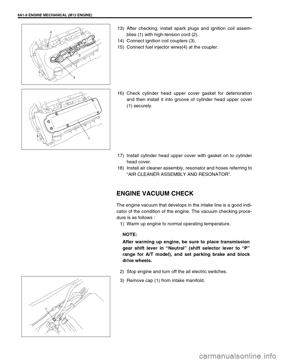
13) After checking, install spark plugs and ignition coil assem-
blies (1) with high-tension cord (2).
14) Connect ignition coil couplers (3).
15) Connect fuel injector wires(4) at the coupler.
16) Check cylinder head upper cover gasket for deterioration
and then install it into groove of cylinder head upper cover
(1) securely.
17) Install cylinder head upper cover with gasket on to cylinder
head cover.
18) Install air cleaner assembly, resonator and hoses referring to
“AIR CLEANER ASSEMBLY AND RESONATOR”.
ENGINE VACUUM CHECK
The engine vacuum that develops in the intake line is a good indi-
cator of the condition of the engine. The vacuum checking proce-
dure is as follows :
1) Warm up engine to normal operating temperature.
2) Stop engine and turn off the all electric switches.
3) Remove cap (1) from intake manifold.
NOTE:
After warming up engine, be sure to place transmission
gear shift lever in “Neutral” (shift selector lever to “P”
range for A/T model), and set parking brake and block
drive wheels.
Page 509 of 698
6A1-8 ENGINE MECHANICAL (M13 ENGINE)
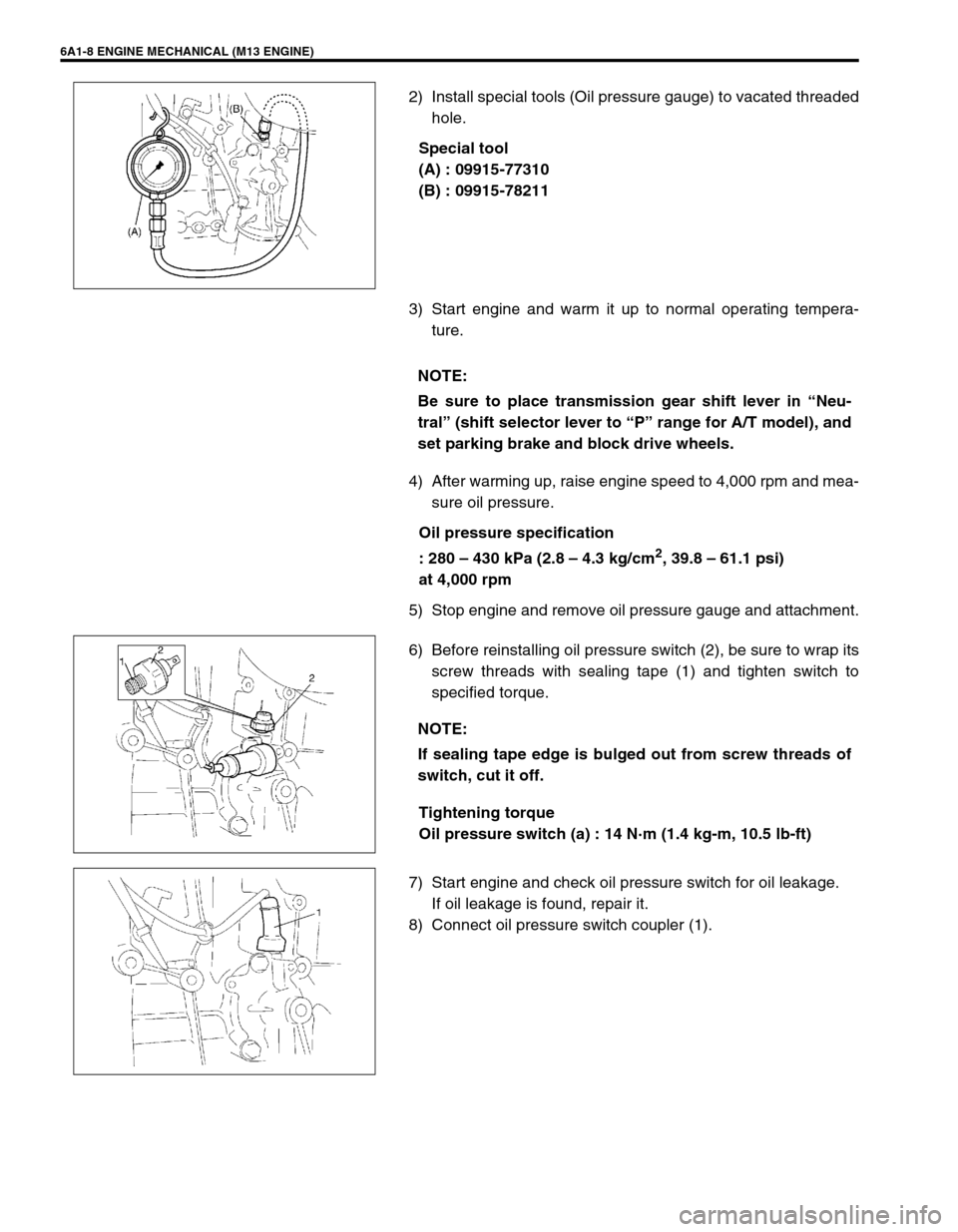
2) Install special tools (Oil pressure gauge) to vacated threaded
hole.
Special tool
(A) : 09915-77310
(B) : 09915-78211
3) Start engine and warm it up to normal operating tempera-
ture.
4) After warming up, raise engine speed to 4,000 rpm and mea-
sure oil pressure.
Oil pressure specification
: 280 – 430 kPa (2.8 – 4.3 kg/cm
2, 39.8 – 61.1 psi)
at 4,000 rpm
5) Stop engine and remove oil pressure gauge and attachment.
6) Before reinstalling oil pressure switch (2), be sure to wrap its
screw threads with sealing tape (1) and tighten switch to
specified torque.
Tightening torque
Oil pressure switch (a) : 14 N·m (1.4 kg-m, 10.5 lb-ft)
7) Start engine and check oil pressure switch for oil leakage.
If oil leakage is found, repair it.
8) Connect oil pressure switch coupler (1).
NOTE:
Be sure to place transmission gear shift lever in “Neu-
tral” (shift selector lever to “P” range for A/T model), and
set parking brake and block drive wheels.
NOTE:
If sealing tape edge is bulged out from screw threads of
switch, cut it off.
Page 569 of 698
6A1-68 ENGINE MECHANICAL (M13 ENGINE)
UNIT REPAIR OVERHAUL
ENGINE ASSEMBLY
REMOVAL
1) Relieve fuel pressure according to procedure described in
Section 6.
2) Disconnect negative and positive cables at battery.
3) Remove engine hood after disconnecting windshield washer
hose.
4) Remove right and left side engine under covers.
5) Remove A/C compressor belt (if equipped).
6) Remove water pump belt.
7) Drain engine oil, transmission oil or A/T fluid (for A/T vehicle)
and transfer oil (for 4WD vehicle).
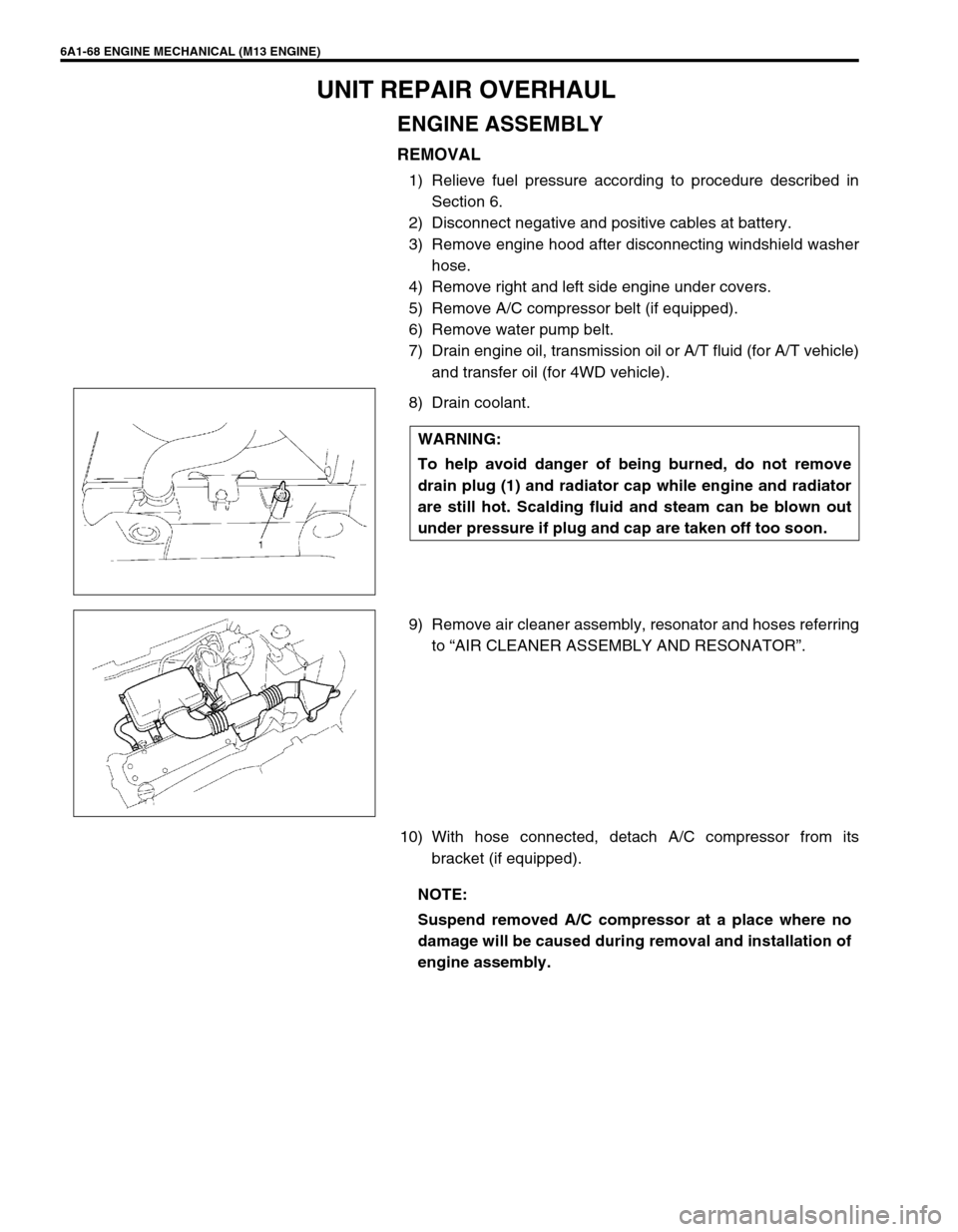
8) Drain coolant.
9) Remove air cleaner assembly, resonator and hoses referring
to “AIR CLEANER ASSEMBLY AND RESONATOR”.
10) With hose connected, detach A/C compressor from its
bracket (if equipped). WARNING:
To help avoid danger of being burned, do not remove
drain plug (1) and radiator cap while engine and radiator
are still hot. Scalding fluid and steam can be blown out
under pressure if plug and cap are taken off too soon.
NOTE:
Suspend removed A/C compressor at a place where no
damage will be caused during removal and installation of
engine assembly.
Page 570 of 698
ENGINE MECHANICAL (M13 ENGINE) 6A1-69
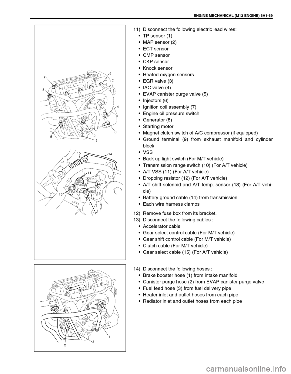
11) Disconnect the following electric lead wires:
TP sensor (1)
MAP sensor (2)
ECT sensor
CMP sensor
CKP sensor
Knock sensor
Heated oxygen sensors
EGR valve (3)
IAC valve (4)
EVAP canister purge valve (5)
Injectors (6)
Ignition coil assembly (7)
Engine oil pressure switch
Generator (8)
Starting motor
Magnet clutch switch of A/C compressor (if equipped)
Ground terminal (9) from exhaust manifold and cylinder
block
VSS
Back up light switch (For M/T vehicle)
Transmission range switch (10) (For A/T vehicle)
A/T VSS (11) (For A/T vehicle)
Dropping resistor (12) (For A/T vehicle)
A/T shift solenoid and A/T temp. sensor (13) (For A/T vehi-
cle)
Battery ground cable (14) from transmission
Each wire harness clamps
12) Remove fuse box from its bracket.
13) Disconnect the following cables :
Accelerator cable
Gear select control cable (For M/T vehicle)
Gear shift control cable (For M/T vehicle)
Clutch cable (For M/T vehicle)
Gear select cable (15) (For A/T vehicle)
14) Disconnect the following hoses :
Brake booster hose (1) from intake manifold
Canister purge hose (2) from EVAP canister purge valve
Fuel feed hose (3) from fuel delivery pipe
Heater inlet and outlet hoses from each pipe
Radiator inlet and outlet hoses from each pipe
Page 626 of 698
ENGINE AND EMISSION CONTROL SYSTEM 6E1-5
AIR INTAKE SYSTEM
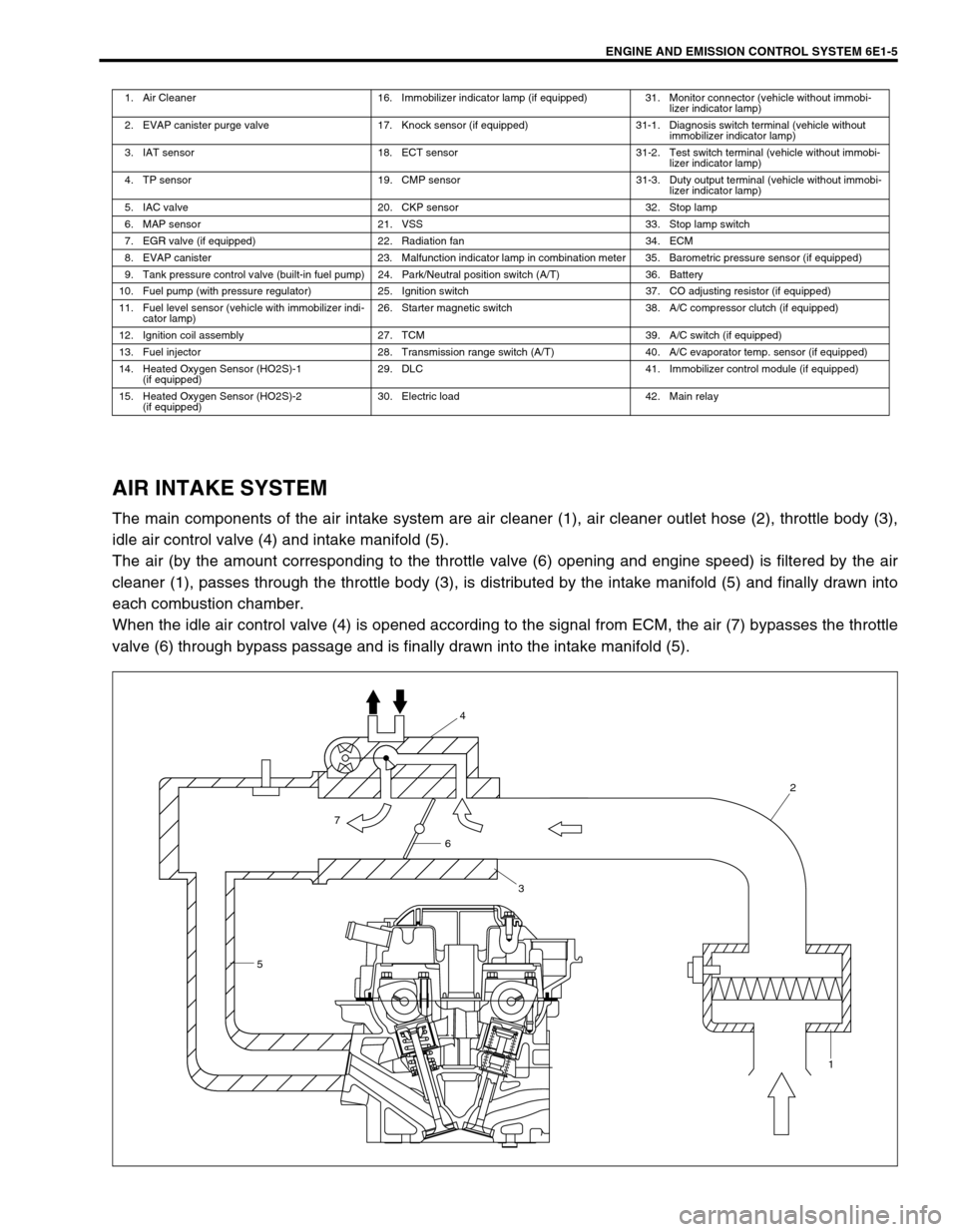
The main components of the air intake system are air cleaner (1), air cleaner outlet hose (2), throttle body (3),
idle air control valve (4) and intake manifold (5).
The air (by the amount corresponding to the throttle valve (6) opening and engine speed) is filtered by the air
cleaner (1), passes through the throttle body (3), is distributed by the intake manifold (5) and finally drawn into
each combustion chamber.
When the idle air control valve (4) is opened according to the signal from ECM, the air (7) bypasses the throttle
valve (6) through bypass passage and is finally drawn into the intake manifold (5).
1. Air Cleaner 16. Immobilizer indicator lamp (if equipped) 31. Monitor connector (vehicle without immobi-
lizer indicator lamp)
2. EVAP canister purge valve 17. Knock sensor (if equipped) 31-1. Diagnosis switch terminal (vehicle without
immobilizer indicator lamp)
3. IAT sensor 18. ECT sensor 31-2. Test switch terminal (vehicle without immobi-
lizer indicator lamp)
4. TP sensor 19. CMP sensor 31-3. Duty output terminal (vehicle without immobi-
lizer indicator lamp)
5. IAC valve 20. CKP sensor 32. Stop lamp
6. MAP sensor 21. VSS 33. Stop lamp switch
7. EGR valve (if equipped) 22. Radiation fan 34. ECM
8. EVAP canister 23. Malfunction indicator lamp in combination meter 35. Barometric pressure sensor (if equipped)
9. Tank pressure control valve (built-in fuel pump) 24. Park/Neutral position switch (A/T) 36. Battery
10. Fuel pump (with pressure regulator) 25. Ignition switch 37. CO adjusting resistor (if equipped)
11. Fuel level sensor (vehicle with immobilizer indi-
cator lamp)26. Starter magnetic switch 38. A/C compressor clutch (if equipped)
12. Ignition coil assembly 27. TCM 39. A/C switch (if equipped)
13. Fuel injector 28. Transmission range switch (A/T) 40. A/C evaporator temp. sensor (if equipped)
14. Heated Oxygen Sensor (HO2S)-1
(if equipped)29. DLC 41. Immobilizer control module (if equipped)
15. Heated Oxygen Sensor (HO2S)-2
(if equipped)30. Electric load 42. Main relay
54
2
1
6
3
7
Page 628 of 698

ENGINE AND EMISSION CONTROL SYSTEM 6E1-7
ELECTRONIC CONTROL SYSTEM
The electronic control system consists of 1) various sensors which detect the state of engine and driving condi-
tions, 2) ECM which controls various devices according to the signals from the sensors and 3) various controlled
devices.
Functionally, it is divided into nine sub systems :
Fuel injection control system
Idle speed control system
Fuel pump control system
A/C control system (if equipped)
Radiator fan control system
EGR system (if equipped)
Evaporative emission control system
Oxygen sensor heater control system (if equipped)
Ignition control system
Also, with A/T model, ECM sends throttle valve opening signal and coolant temp. signal to transmission control
module to control A/T.
INFORMATION SENSORS CONTROL DEVICES OTHERS
1. MAP sensor a : Fuel injector A : ECM
2. TP sensor b : EVAP canister purge valve B : Main relay
3. IAT sensor c : Fuel pump relay C : EVAP canister
4. ECT sensor d : EGR valve (step motor) (if equipped) D : Monitor connector
5. Heated oxygen sensor-1 (if equipped) e : Malfunction indicator lamp E : Data link connector
5-1. Heated oxygen sensor-2 (if equipped) f : Ignition coil assembly F : A/C EVAP thermistor (if equipped)
6. VSS g : Radiator fan control relay G : TCM (A/T)
7. Transmission range switch (A/T) h : IAC valve
8. Battery i : Immobilizer indicator lamp
9. CMP sensor
10. CKP sensor
11. Fuel level sensor (gauge) (in fuel tank)
12. Stop lamp switch
13. Knock sensor (if equipped)
Page 629 of 698
6E1-8 ENGINE AND EMISSION CONTROL SYSTEM
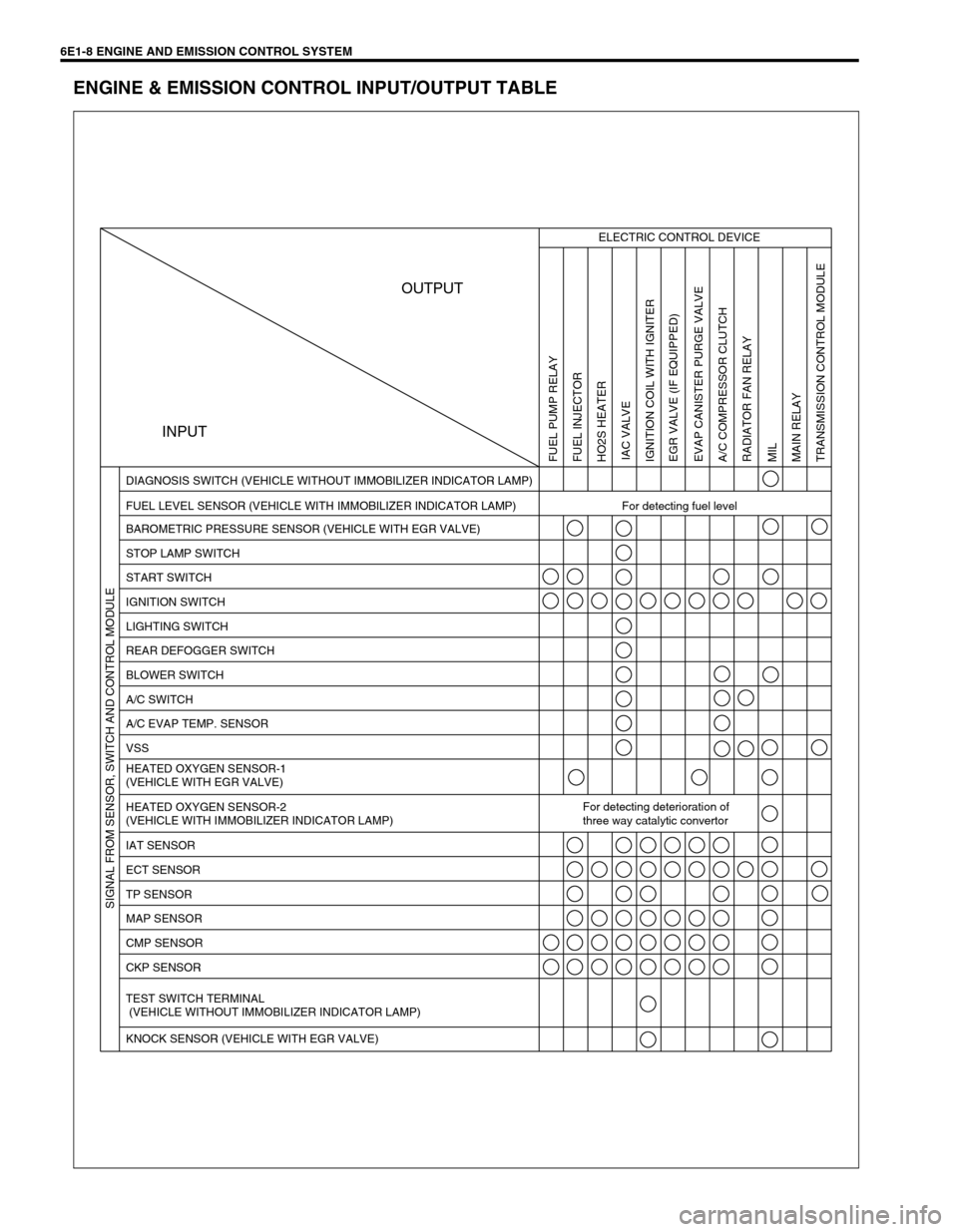
ENGINE & EMISSION CONTROL INPUT/OUTPUT TABLE
INPUTOUTPUT
ELECTRIC CONTROL DEVICE
FUEL LEVEL SENSOR (VEHICLE WITH IMMOBILIZER INDICATOR LAMP) For detecting fuel level DIAGNOSIS SWITCH (VEHICLE WITHOUT IMMOBILIZER INDICATOR LAMP)
BAROMETRIC PRESSURE SENSOR (VEHICLE WITH EGR VALVE)
STOP LAMP SWITCH
START SWITCH
IGNITION SWITCH
LIGHTING SWITCH
REAR DEFOGGER SWITCH
BLOWER SWITCH
A/C SWITCH
A/C EVAP TEMP. SENSOR
VSS
HEATED OXYGEN SENSOR-1
(VEHICLE WITH EGR VALVE)
HEATED OXYGEN SENSOR-2
(VEHICLE WITH IMMOBILIZER INDICATOR LAMP)For detecting deterioration of
three way catalytic convertor
IAT SENSOR
ECT SENSOR
TP SENSOR
MAP SENSOR
CMP SENSOR
CKP SENSOR
TEST SWITCH TERMINAL
(VEHICLE WITHOUT IMMOBILIZER INDICATOR LAMP)
KNOCK SENSOR (VEHICLE WITH EGR VALVE)
FUEL PUMP RELAY
FUEL INJECTOR
HO2S HEATER
IAC VALVE
IGNITION COIL WITH IGNITER
EGR VALVE (IF EQUIPPED)
EVAP CANISTER PURGE VALVE
A/C COMPRESSOR CLUTCH
RADIATOR FAN RELAY
MIL
MAIN RELAY
TRANSMISSION CONTROL MODULE SIGNAL FROM SENSOR, SWITCH AND CONTROL MODULE
Page 631 of 698
6E1-10 ENGINE AND EMISSION CONTROL SYSTEM
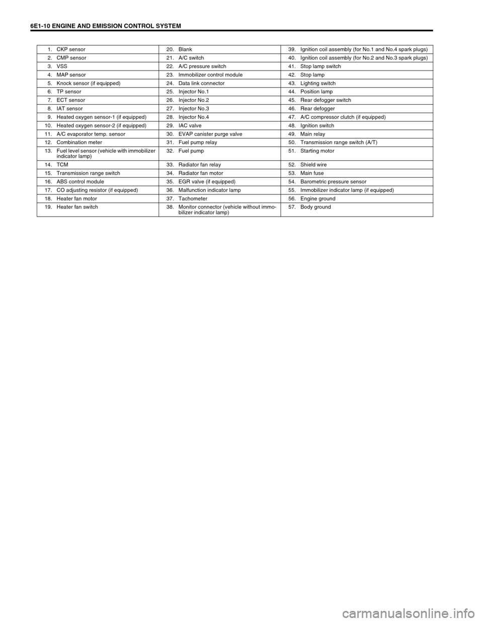
1. CKP sensor 20. Blank 39. Ignition coil assembly (for No.1 and No.4 spark plugs)
2. CMP sensor 21. A/C switch 40. Ignition coil assembly (for No.2 and No.3 spark plugs)
3. VSS 22. A/C pressure switch 41. Stop lamp switch
4. MAP sensor 23. Immobilizer control module 42. Stop lamp
5. Knock sensor (if equipped) 24. Data link connector 43. Lighting switch
6. TP sensor 25. Injector No.1 44. Position lamp
7. ECT sensor 26. Injector No.2 45. Rear defogger switch
8. IAT sensor 27. Injector No.3 46. Rear defogger
9. Heated oxygen sensor-1 (if equipped) 28. Injector No.4 47. A/C compressor clutch (if equipped)
10. Heated oxygen sensor-2 (if equipped) 29. IAC valve 48. Ignition switch
11. A/C evaporator temp. sensor 30. EVAP canister purge valve 49. Main relay
12. Combination meter 31. Fuel pump relay 50. Transmission range switch (A/T)
13. Fuel level sensor (vehicle with immobilizer
indicator lamp)32. Fuel pump 51. Starting motor
14. TCM 33. Radiator fan relay 52. Shield wire
15. Transmission range switch 34. Radiator fan motor 53. Main fuse
16. ABS control module 35. EGR valve (if equipped) 54. Barometric pressure sensor
17. CO adjusting resistor (if equipped) 36. Malfunction indicator lamp 55. Immobilizer indicator lamp (if equipped)
18. Heater fan motor 37. Tachometer 56. Engine ground
19. Heater fan switch 38. Monitor connector (vehicle without immo-
bilizer indicator lamp)57. Body ground