parking brake SUZUKI SWIFT 2000 1.G RG413 Service Workshop Manual
[x] Cancel search | Manufacturer: SUZUKI, Model Year: 2000, Model line: SWIFT, Model: SUZUKI SWIFT 2000 1.GPages: 698, PDF Size: 16.01 MB
Page 9 of 698
0A-6 GENERAL INFORMATION
Air bag wire harness can be identified easily as it is covered with a yellow protection tube. Be very
careful when handling it.
When an open in air bag wire harness, damaged wire harness, connector or terminal is found,
replace wire harness, connectors and terminals as an assembly.
Do not apply power to the air bag system unless all components are connected or a diagnostic chart
requests it, as this will set a diagnostic trouble code.
Never use air bag system component parts from another vehicle.
When using electric welding, be sure to temporarily disable air bag system referring to “DISABLING
AIR BAG SYSTEM” in Section 10B.
Never expose air bag system component parts directly to hot air (drying or baking the vehicle after
painting) or flames.
WARNING/CAUTION labels are attached on each part of air bag system components. Be sure to fol-
low the instructions.
After vehicle is completely repaired, perform “AIR BAG DIAGNOSTIC SYSTEM CHECK” in SECTION
10B.
GENERAL PRECAUTIONS
The WARNING and CAUTION below describe some general precautions that you should observe when servic-
ing a vehicle. These general precautions apply to many of the service procedures described in this manual, and
they will not necessarily be repeated with each procedure to which they apply.
WARNING:
Whenever raising a vehicle for service, be sure to follow the instructions under “VEHICLE LIFTING
POINTS” in this section.
When it is necessary to do service work with the engine running, make sure that the parking brake
is set fully and the transmission is in Neutral (for manual transmission vehicles) or Park (for auto-
matic transmission vehicles), Keep hands, hair, clothing, tools, etc. away from the fan and belts
when the engine is running.
When it is necessary to run the engine indoors, make sure that the exhaust gas is forced outdoors.
Do not perform service work in areas where combustible materials can come in contact with a hot
exhaust system. When working with toxic or flammable materials (such as gasoline and refriger-
ant), make sure that the area you work in is well-ventilated.
To avoid getting burned, keep away from hot metal parts such as the radiator, exhaust manifold, tail
pipe, muffler, etc.
New and used engine oil can be hazardous. Children and pets may be harmed by swallowing new or
used oil. Keep new and used oil and used engine oil filters away from children and pets.
Continuous contact with used engine oil has been found to cause [skin] cancer in laboratory ani-
mals. Brief contact with used oil may irritate skin. To minimize your exposure to used engine oil,
wear a long-sleeve shirt and moisture-proof gloves (such as dish washing gloves) when changing
engine oil. If engine oil contacts your skin, wash thoroughly with soap and water. Launder any
clothing or rags if wet with oil, recycle or properly dispose of used oil and filters.
Make sure the bonnet is fully closed and latched before driving. If it is not, it can fly up unexpect-
edly during driving, obstructing your view and resulting in an accident.
Page 43 of 698
0B-14 MAINTENANCE AND LUBRICATION
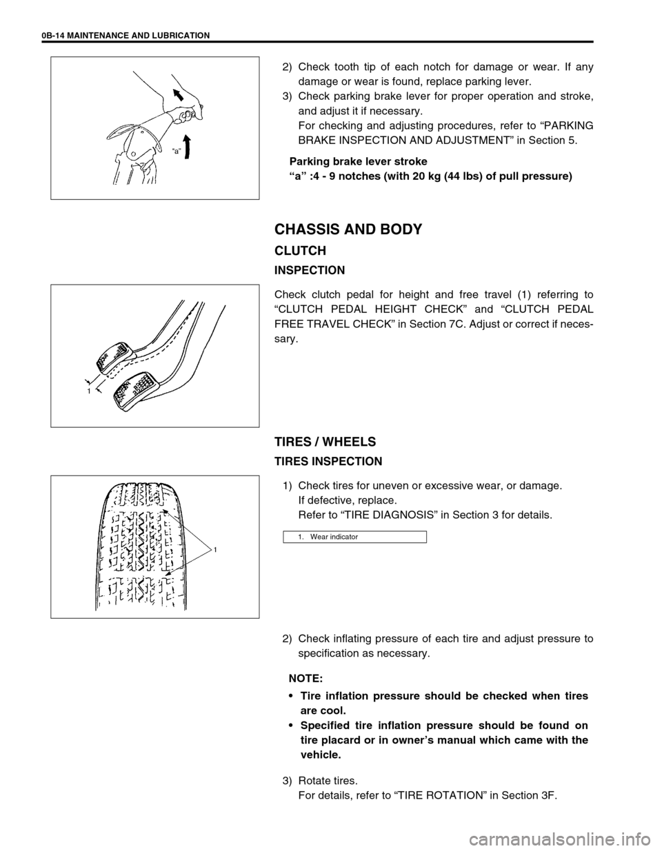
2) Check tooth tip of each notch for damage or wear. If any
damage or wear is found, replace parking lever.
3) Check parking brake lever for proper operation and stroke,
and adjust it if necessary.
For checking and adjusting procedures, refer to “PARKING
BRAKE INSPECTION AND ADJUSTMENT” in Section 5.
Parking brake lever stroke
“a” :4 - 9 notches (with 20 kg (44 lbs) of pull pressure)
CHASSIS AND BODY
CLUTCH
INSPECTION
Check clutch pedal for height and free travel (1) referring to
“CLUTCH PEDAL HEIGHT CHECK” and “CLUTCH PEDAL
FREE TRAVEL CHECK” in Section 7C. Adjust or correct if neces-
sary.
TIRES / WHEELS
TIRES INSPECTION
1) Check tires for uneven or excessive wear, or damage.
If defective, replace.
Refer to “TIRE DIAGNOSIS” in Section 3 for details.
2) Check inflating pressure of each tire and adjust pressure to
specification as necessary.
3) Rotate tires.
For details, refer to “TIRE ROTATION” in Section 3F.
1. Wear indicator
NOTE:
Tire inflation pressure should be checked when tires
are cool.
Specified tire inflation pressure should be found on
tire placard or in owner’s manual which came with the
vehicle.
Page 49 of 698
0B-20 MAINTENANCE AND LUBRICATION
ENGINE START
Check engine start for readiness.
On automatic transmission vehicles, try to start the engine in each select lever position. The starting motor
should crank only in “P” (Park) or “N” (Neutral).
On manual transmission vehicles, place the shift lever in “Neutral,” depress clutch pedal fully any try to start.
EXHAUST SYSTEM CHECK
Check for leakage, cracks or loose supports.
CLUTCH (FOR MANUAL TRANSMISSION)
Check for the following.
Clutch is completely released when depressing clutch pedal,
No slipping clutch occurs when releasing pedal and accelerating.
Clutch itself is free from any abnormal condition.
GEARSHIFT OR SELECT LEVER (TRANSMISSION)
Check gear shift or select lever for smooth shifting to all positions and for good performance of transmission in
any position.
With automatic transmission equipped vehicle, also check that shift indicator indicates properly according to
which position select lever is shifted to.
With automatic transmission equipped vehicle, make sure that vehicle is at complete stop when shifting select
lever to “P” range position and release all brakes.
BRAKE
Foot Brake
Check the followings:
that brake pedal has proper travel,
that brake works properly,
that it is free from noise,
that vehicle does not pull to one side when brake is applied.
and that brake do not drag.
Parking Brake
Check that lever has proper travel.
Check to ensure that parking brake is fully effective when the vehicle is stopped on the safe slope and brake
lever is pulled all the way.WARNING:
Before performing the following check, be sure to have enough room around the vehicle. Then, firmly
apply both the parking brake and the regular brakes. Do not use the accelerator pedal. If the engine
starts, be ready to turn off the ignition promptly. Take these precautions because the vehicle could
move without warning and possibly cause personal injury or property damage.
WARNING:
With vehicle parked on a fairly steep slope, make sure nothing is in the way downhill to avoid any per-
sonal injury or property damage. Be prepared to apply regular brake quickly even if vehicle should
start to move.
Page 149 of 698
3B1-8 ELECTRICAL POWER STEERING (P/S) SYSTEM
DTC CHECK
USING SUZUKI SCAN TOOL
1) Turn ignition switch to OFF position.
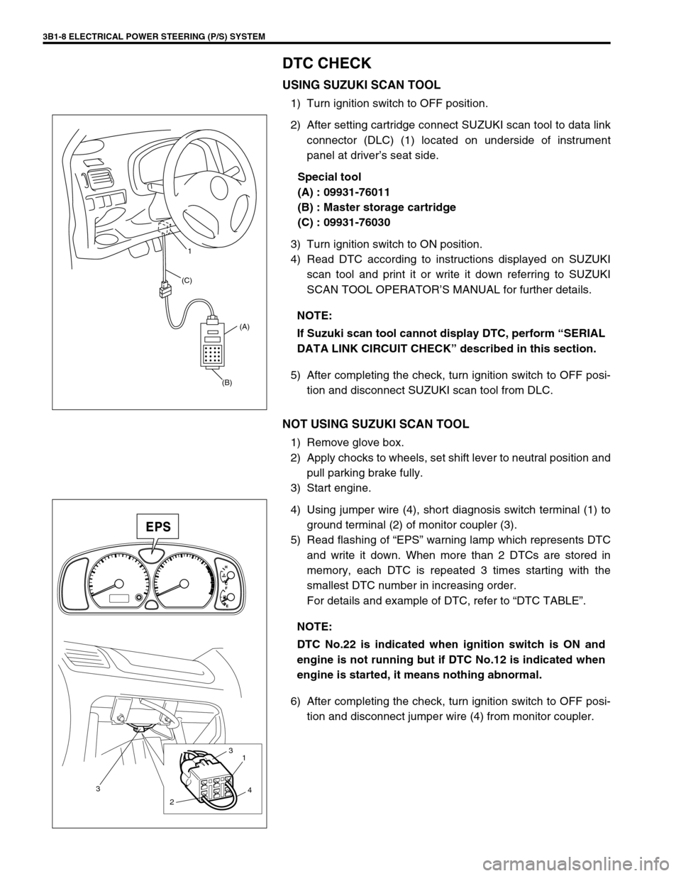
2) After setting cartridge connect SUZUKI scan tool to data link
connector (DLC) (1) located on underside of instrument
panel at driver’s seat side.
Special tool
(A) : 09931-76011
(B) : Master storage cartridge
(C) : 09931-76030
3) Turn ignition switch to ON position.
4) Read DTC according to instructions displayed on SUZUKI
scan tool and print it or write it down referring to SUZUKI
SCAN TOOL OPERATOR’S MANUAL for further details.
5) After completing the check, turn ignition switch to OFF posi-
tion and disconnect SUZUKI scan tool from DLC.
NOT USING SUZUKI SCAN TOOL
1) Remove glove box.
2) Apply chocks to wheels, set shift lever to neutral position and
pull parking brake fully.
3) Start engine.
4) Using jumper wire (4), short diagnosis switch terminal (1) to
ground terminal (2) of monitor coupler (3).
5) Read flashing of “EPS” warning lamp which represents DTC
and write it down. When more than 2 DTCs are stored in
memory, each DTC is repeated 3 times starting with the
smallest DTC number in increasing order.
For details and example of DTC, refer to “DTC TABLE”.
6) After completing the check, turn ignition switch to OFF posi-
tion and disconnect jumper wire (4) from monitor coupler. NOTE:
If Suzuki scan tool cannot display DTC, perform “SERIAL
DATA LINK CIRCUIT CHECK” described in this section.
(B)(A) (C)1
NOTE:
DTC No.22 is indicated when ignition switch is ON and
engine is not running but if DTC No.12 is indicated when
engine is started, it means nothing abnormal.
3
21
3
4
Page 155 of 698
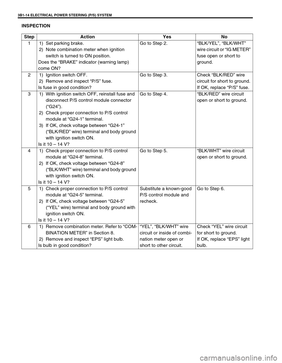
3B1-14 ELECTRICAL POWER STEERING (P/S) SYSTEM
INSPECTION
Step Action Yes No
1 1) Set parking brake.
2) Note combination meter when ignition
switch is turned to ON position.
Does the “BRAKE” indicator (warning lamp)
come ON?Go to Step 2.“BLK/YEL”, “BLK/WHT”
wire circuit or “IG METER”
fuse open or short to
ground.
2 1) Ignition switch OFF.
2) Remove and inspect “P/S” fuse.
Is fuse in good condition?Go to Step 3. Check “BLK/RED” wire
circuit for short to ground.
If OK, replace “P/S” fuse.
3 1) With ignition switch OFF, reinstall fuse and
disconnect P/S control module connector
(“G24”).
2) Check proper connection to P/S control
module at “G24-1” terminal.
3) If OK, check voltage between “G24-1”
(“BLK/RED” wire) terminal and body ground
with ignition switch ON.
Is it 10 – 14 V?Go to Step 4.“BLK/RED” wire circuit
open or short to ground.
4 1) Check proper connection to P/S control
module at “G24-8” terminal.
2) If OK, check voltage between “G24-8”
(“BLK/WHT” wire) terminal and body ground
with ignition switch ON.
Is it 10 – 14 V?Go to Step 5.“BLK/WHT” wire circuit
open or short to ground.
5 1) Check proper connection to P/S control
module at “G24-5” terminal.
2) If OK, check voltage between “G24-5”
(“YEL” wire) terminal and body ground with
ignition switch ON.
Is it 10 – 14 V?Substitute a known-good
P/S control module and
recheck.Go to Step 6.
6 1) Remove combination meter. Refer to “COM-
BINATION METER” in Section 8.
2) Remove and inspect “EPS” light bulb.
Is bulb in good condition?“YEL”, “BLK/WHT” wire
circuit or inside of combi-
nation meter open or
short to other circuit.Check “YEL” wire circuit
for short to ground.
If OK, replace “EPS” light
bulb.
Page 225 of 698
3E-12 REAR SUSPENSION
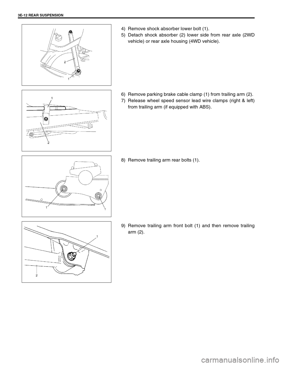
4) Remove shock absorber lower bolt (1).
5) Detach shock absorber (2) lower side from rear axle (2WD
vehicle) or rear axle housing (4WD vehicle).
6) Remove parking brake cable clamp (1) from trailing arm (2).
7) Release wheel speed sensor lead wire clamps (right & left)
from trailing arm (if equipped with ABS).
8) Remove trailing arm rear bolts (1).
9) Remove trailing arm front bolt (1) and then remove trailing
arm (2).
Page 226 of 698
REAR SUSPENSION 3E-13
INSTALLATION
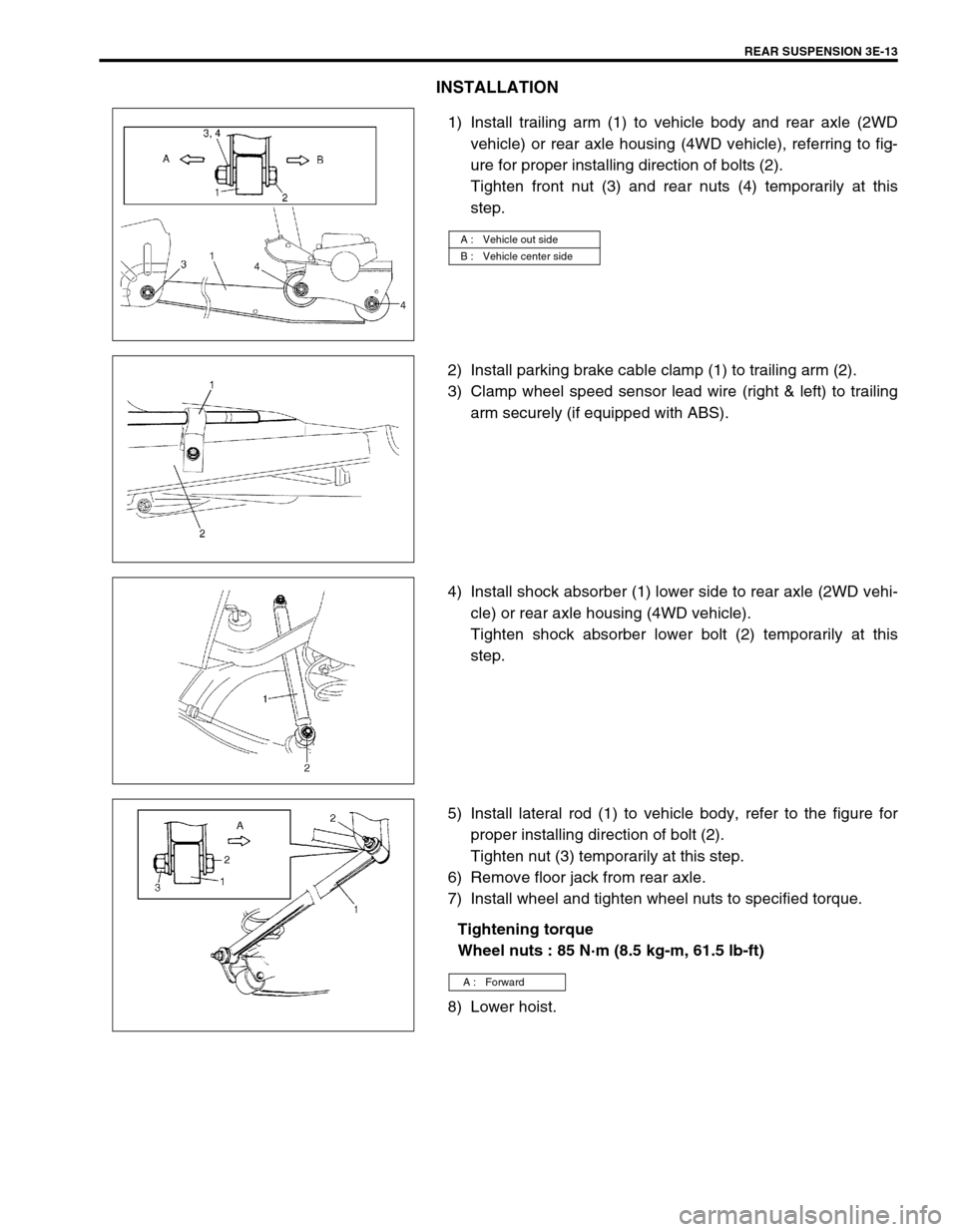
1) Install trailing arm (1) to vehicle body and rear axle (2WD
vehicle) or rear axle housing (4WD vehicle), referring to fig-
ure for proper installing direction of bolts (2).
Tighten front nut (3) and rear nuts (4) temporarily at this
step.
2) Install parking brake cable clamp (1) to trailing arm (2).
3) Clamp wheel speed sensor lead wire (right & left) to trailing
arm securely (if equipped with ABS).
4) Install shock absorber (1) lower side to rear axle (2WD vehi-
cle) or rear axle housing (4WD vehicle).
Tighten shock absorber lower bolt (2) temporarily at this
step.
5) Install lateral rod (1) to vehicle body, refer to the figure for
proper installing direction of bolt (2).
Tighten nut (3) temporarily at this step.
6) Remove floor jack from rear axle.
7) Install wheel and tighten wheel nuts to specified torque.
Tightening torque
Wheel nuts : 85 N·m (8.5 kg-m, 61.5 lb-ft)
8) Lower hoist.
A : Vehicle out side
B : Vehicle center side
A : Forward
Page 232 of 698
REAR SUSPENSION 3E-19
15) Upon completion of all jobs, depress brake pedal with about
30 kg (66 Ibs) load three to five times so as to obtain proper
drum-to-shoe clearance.
Adjust parking brake cable. Refer to Section 5.
16) Install console box.
17) Lower hoist and bounce vehicle up and down several times
to stabilize suspension.
Be sure that vehicle is off hoist and in non loaded condition.
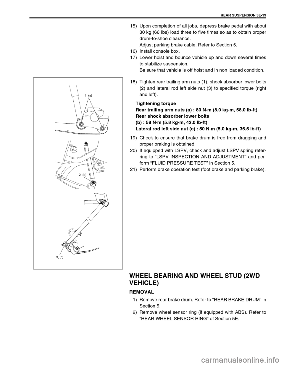
18) Tighten rear trailing arm nuts (1), shock absorber lower bolts
(2) and lateral rod left side nut (3) to specified torque (right
and left).
Tightening torque
Rear trailing arm nuts (a) : 80 N·m (8.0 kg-m, 58.0 lb-ft)
Rear shock absorber lower bolts
(b) : 58 N·m (5.8 kg-m, 42.0 lb-ft)
Lateral rod left side nut (c) : 50 N·m (5.0 kg-m, 36.5 lb-ft)
19) Check to ensure that brake drum is free from dragging and
proper braking is obtained.
20) If equipped with LSPV, check and adjust LSPV spring refer-
ring to “LSPV INSPECTION AND ADJUSTMENT” and per-
form “FLUID PRESSURE TEST” in Section 5.
21) Perform brake operation test (foot brake and parking brake).
WHEEL BEARING AND WHEEL STUD (2WD
VEHICLE)
REMOVAL
1) Remove rear brake drum. Refer to “REAR BRAKE DRUM” in
Section 5.
2) Remove wheel sensor ring (if equipped with ABS). Refer to
“REAR WHEEL SENSOR RING” of Section 5E.
Page 235 of 698
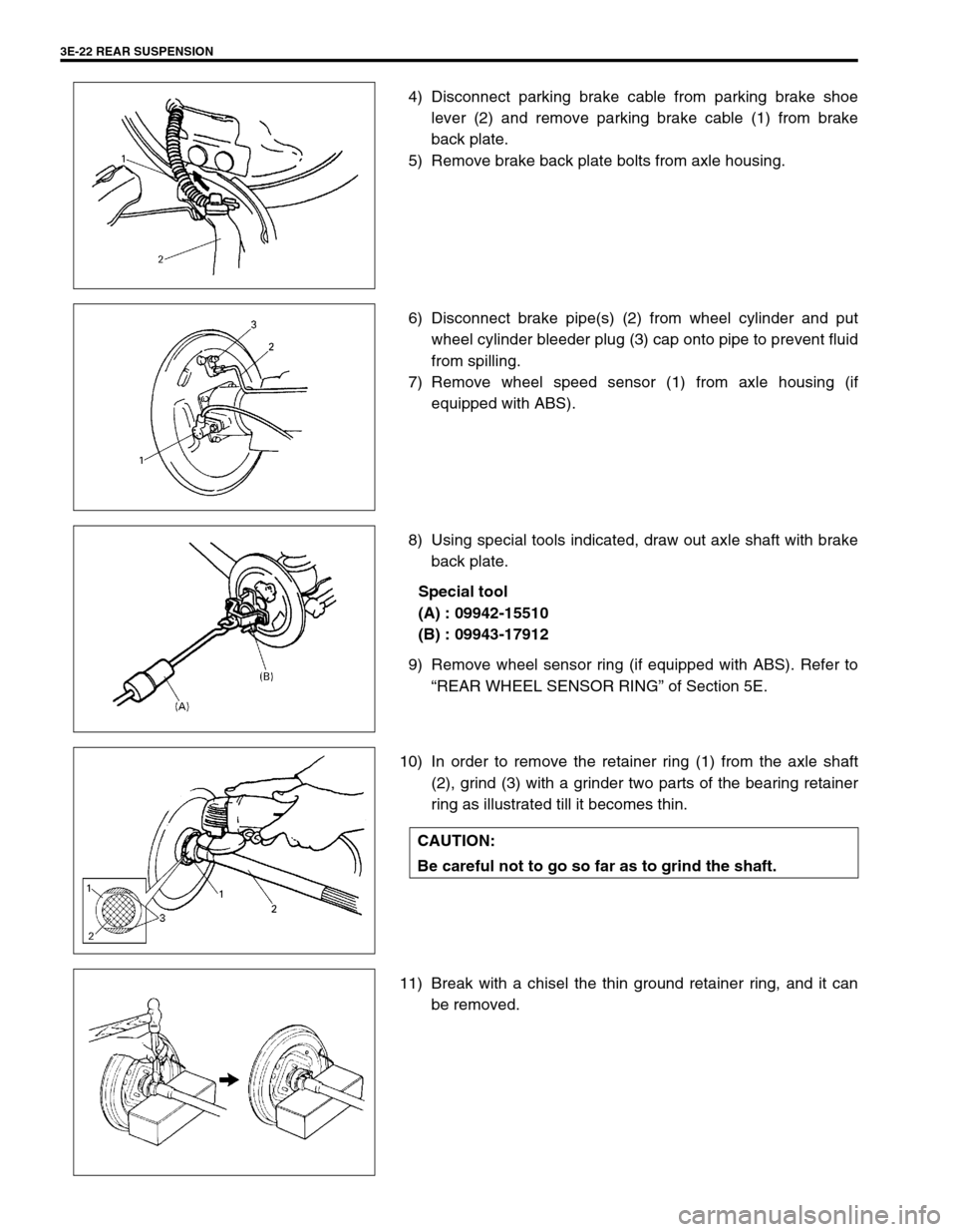
3E-22 REAR SUSPENSION
4) Disconnect parking brake cable from parking brake shoe
lever (2) and remove parking brake cable (1) from brake
back plate.
5) Remove brake back plate bolts from axle housing.
6) Disconnect brake pipe(s) (2) from wheel cylinder and put
wheel cylinder bleeder plug (3) cap onto pipe to prevent fluid
from spilling.
7) Remove wheel speed sensor (1) from axle housing (if
equipped with ABS).
8) Using special tools indicated, draw out axle shaft with brake
back plate.
Special tool
(A) : 09942-15510
(B) : 09943-17912
9) Remove wheel sensor ring (if equipped with ABS). Refer to
“REAR WHEEL SENSOR RING” of Section 5E.
10) In order to remove the retainer ring (1) from the axle shaft
(2), grind (3) with a grinder two parts of the bearing retainer
ring as illustrated till it becomes thin.
11) Break with a chisel the thin ground retainer ring, and it can
be removed.
CAUTION:
Be careful not to go so far as to grind the shaft.
Page 238 of 698
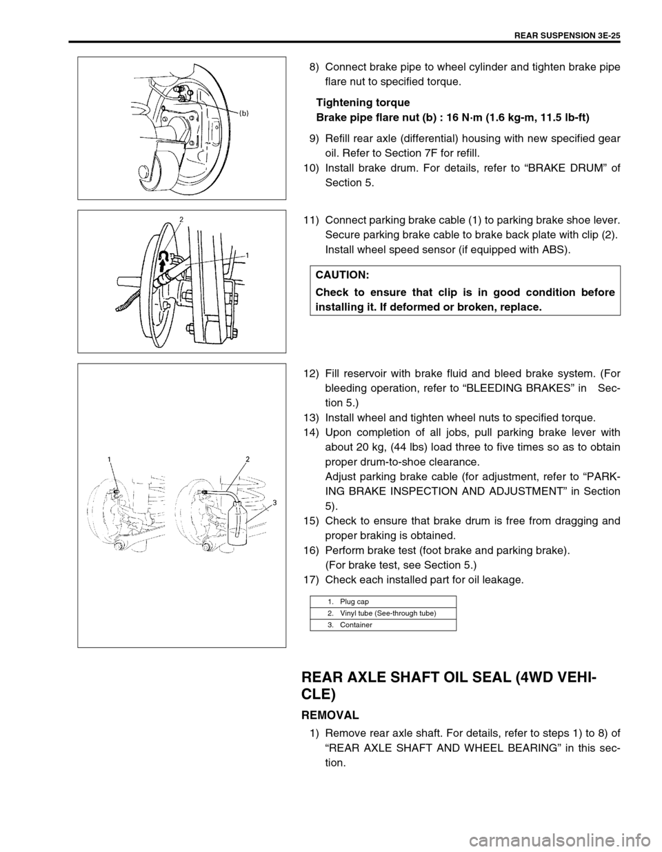
REAR SUSPENSION 3E-25
8) Connect brake pipe to wheel cylinder and tighten brake pipe
flare nut to specified torque.
Tightening torque
Brake pipe flare nut (b) : 16 N·m (1.6 kg-m, 11.5 lb-ft)
9) Refill rear axle (differential) housing with new specified gear
oil. Refer to Section 7F for refill.
10) Install brake drum. For details, refer to “BRAKE DRUM” of
Section 5.
11) Connect parking brake cable (1) to parking brake shoe lever.
Secure parking brake cable to brake back plate with clip (2).
Install wheel speed sensor (if equipped with ABS).
12) Fill reservoir with brake fluid and bleed brake system. (For
bleeding operation, refer to “BLEEDING BRAKES” in Sec-
tion 5.)
13) Install wheel and tighten wheel nuts to specified torque.
14) Upon completion of all jobs, pull parking brake lever with
about 20 kg, (44 lbs) load three to five times so as to obtain
proper drum-to-shoe clearance.
Adjust parking brake cable (for adjustment, refer to “PARK-
ING BRAKE INSPECTION AND ADJUSTMENT” in Section
5).
15) Check to ensure that brake drum is free from dragging and
proper braking is obtained.
16) Perform brake test (foot brake and parking brake).
(For brake test, see Section 5.)
17) Check each installed part for oil leakage.
REAR AXLE SHAFT OIL SEAL (4WD VEHI-
CLE)
REMOVAL
1) Remove rear axle shaft. For details, refer to steps 1) to 8) of
“REAR AXLE SHAFT AND WHEEL BEARING” in this sec-
tion.
CAUTION:
Check to ensure that clip is in good condition before
installing it. If deformed or broken, replace.
1. Plug cap
2. Vinyl tube (See-through tube)
3. Container