SUZUKI SWIFT 2000 1.G RG413 Service Workshop Manual
Manufacturer: SUZUKI, Model Year: 2000, Model line: SWIFT, Model: SUZUKI SWIFT 2000 1.GPages: 698, PDF Size: 16.01 MB
Page 261 of 698
4A-8 FRONT DRIVE SHAFT
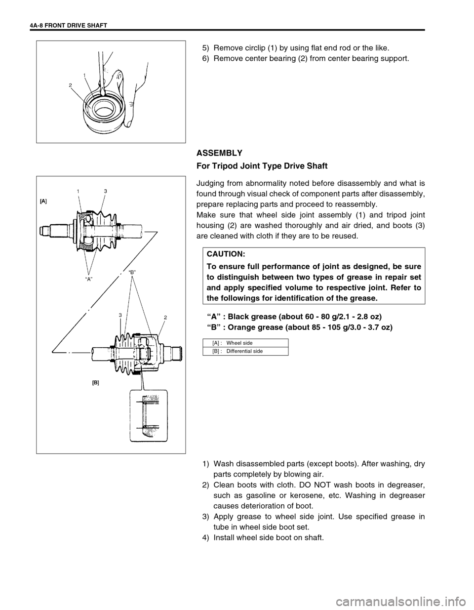
5) Remove circlip (1) by using flat end rod or the like.
6) Remove center bearing (2) from center bearing support.
ASSEMBLY
For Tripod Joint Type Drive Shaft
Judging from abnormality noted before disassembly and what is
found through visual check of component parts after disassembly,
prepare replacing parts and proceed to reassembly.
Make sure that wheel side joint assembly (1) and tripod joint
housing (2) are washed thoroughly and air dried, and boots (3)
are cleaned with cloth if they are to be reused.
“A” : Black grease (about 60 - 80 g/2.1 - 2.8 oz)
“B” : Orange grease (about 85 - 105 g/3.0 - 3.7 oz)
1) Wash disassembled parts (except boots). After washing, dry
parts completely by blowing air.
2) Clean boots with cloth. DO NOT wash boots in degreaser,
such as gasoline or kerosene, etc. Washing in degreaser
causes deterioration of boot.
3) Apply grease to wheel side joint. Use specified grease in
tube in wheel side boot set.
4) Install wheel side boot on shaft.
CAUTION:
To ensure full performance of joint as designed, be sure
to distinguish between two types of grease in repair set
and apply specified volume to respective joint. Refer to
the followings for identification of the grease.
[A] : Wheel side
[B] : Differential side
Page 262 of 698
FRONT DRIVE SHAFT 4A-9
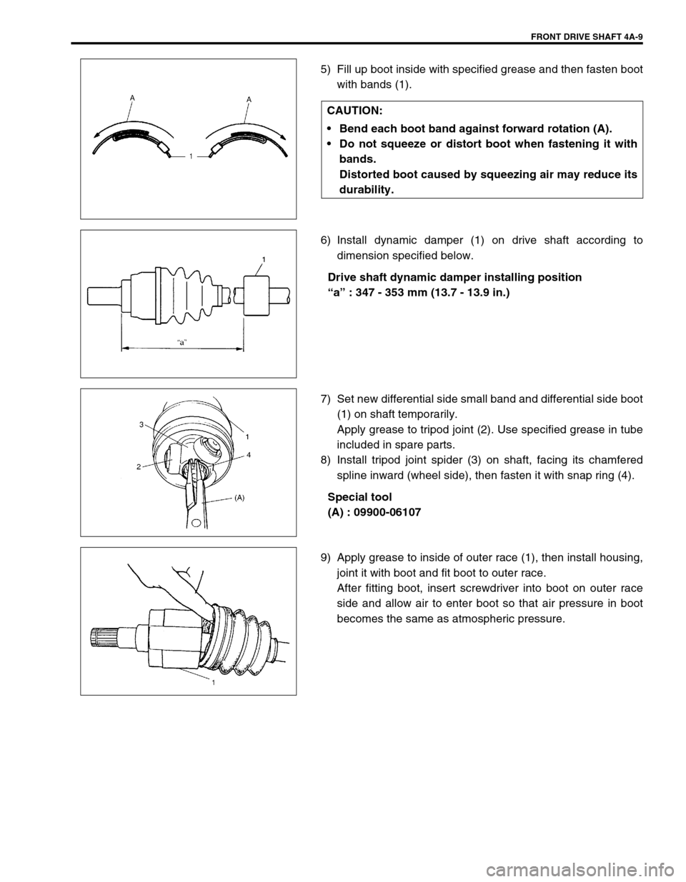
5) Fill up boot inside with specified grease and then fasten boot
with bands (1).
6) Install dynamic damper (1) on drive shaft according to
dimension specified below.
Drive shaft dynamic damper installing position
“a” : 347 - 353 mm (13.7 - 13.9 in.)
7) Set new differential side small band and differential side boot
(1) on shaft temporarily.
Apply grease to tripod joint (2). Use specified grease in tube
included in spare parts.
8) Install tripod joint spider (3) on shaft, facing its chamfered
spline inward (wheel side), then fasten it with snap ring (4).
Special tool
(A) : 09900-06107
9) Apply grease to inside of outer race (1), then install housing,
joint it with boot and fit boot to outer race.
After fitting boot, insert screwdriver into boot on outer race
side and allow air to enter boot so that air pressure in boot
becomes the same as atmospheric pressure. CAUTION:
Bend each boot band against forward rotation (A).
Do not squeeze or distort boot when fastening it with
bands.
Distorted boot caused by squeezing air may reduce its
durability.
Page 263 of 698
4A-10 FRONT DRIVE SHAFT
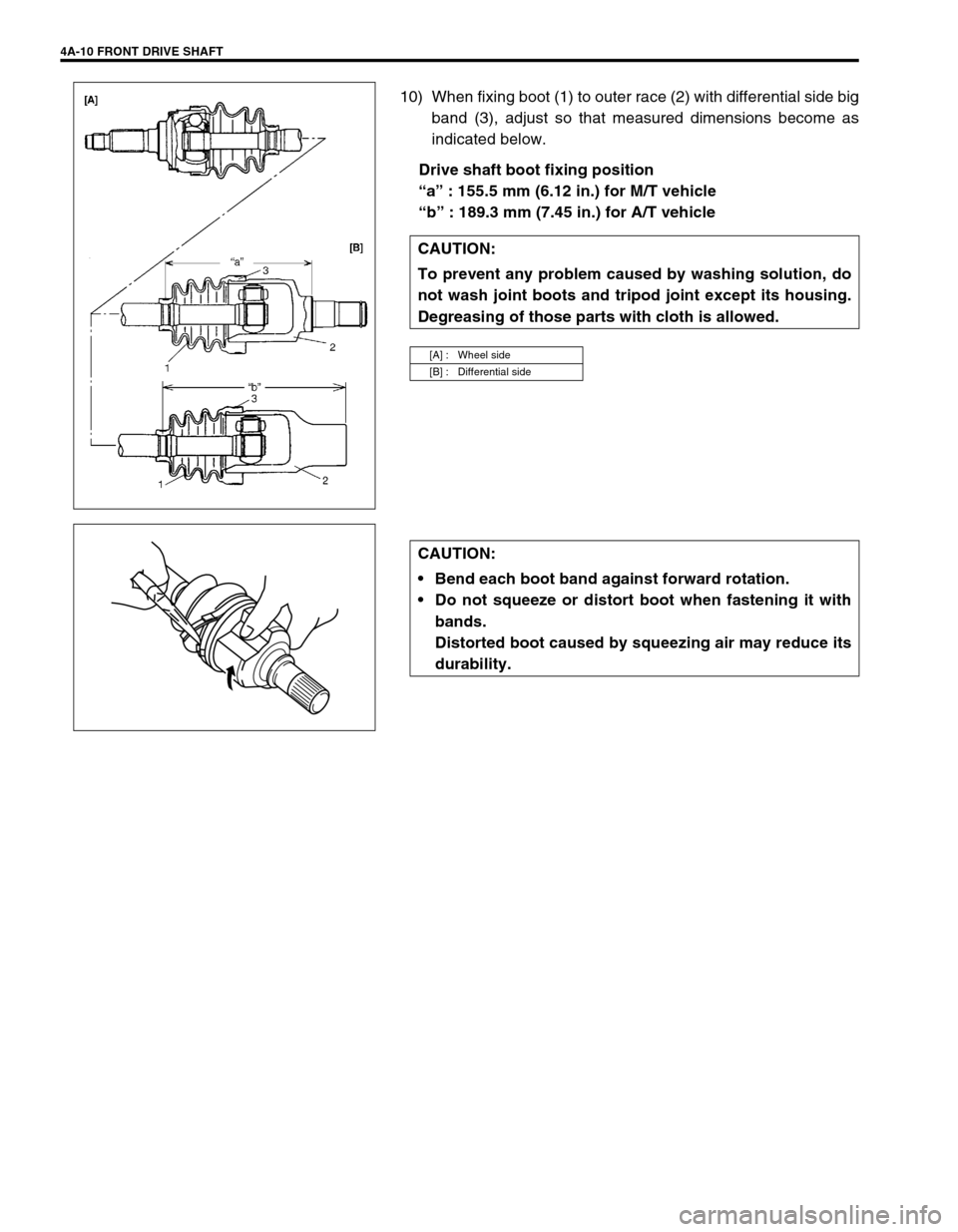
10) When fixing boot (1) to outer race (2) with differential side big
band (3), adjust so that measured dimensions become as
indicated below.
Drive shaft boot fixing position
“a” : 155.5 mm (6.12 in.) for M/T vehicle
“b” : 189.3 mm (7.45 in.) for A/T vehicle
CAUTION:
To prevent any problem caused by washing solution, do
not wash joint boots and tripod joint except its housing.
Degreasing of those parts with cloth is allowed.
[A] : Wheel side
[B] : Differential side
CAUTION:
Bend each boot band against forward rotation.
Do not squeeze or distort boot when fastening it with
bands.
Distorted boot caused by squeezing air may reduce its
durability.
Page 264 of 698
FRONT DRIVE SHAFT 4A-11
For DOJ Type Drive Shaft
Judging from abnormality noted before disassembly and what is
found though visual check of component parts after disassembly,
prepare replacing parts and proceed to reassembly.
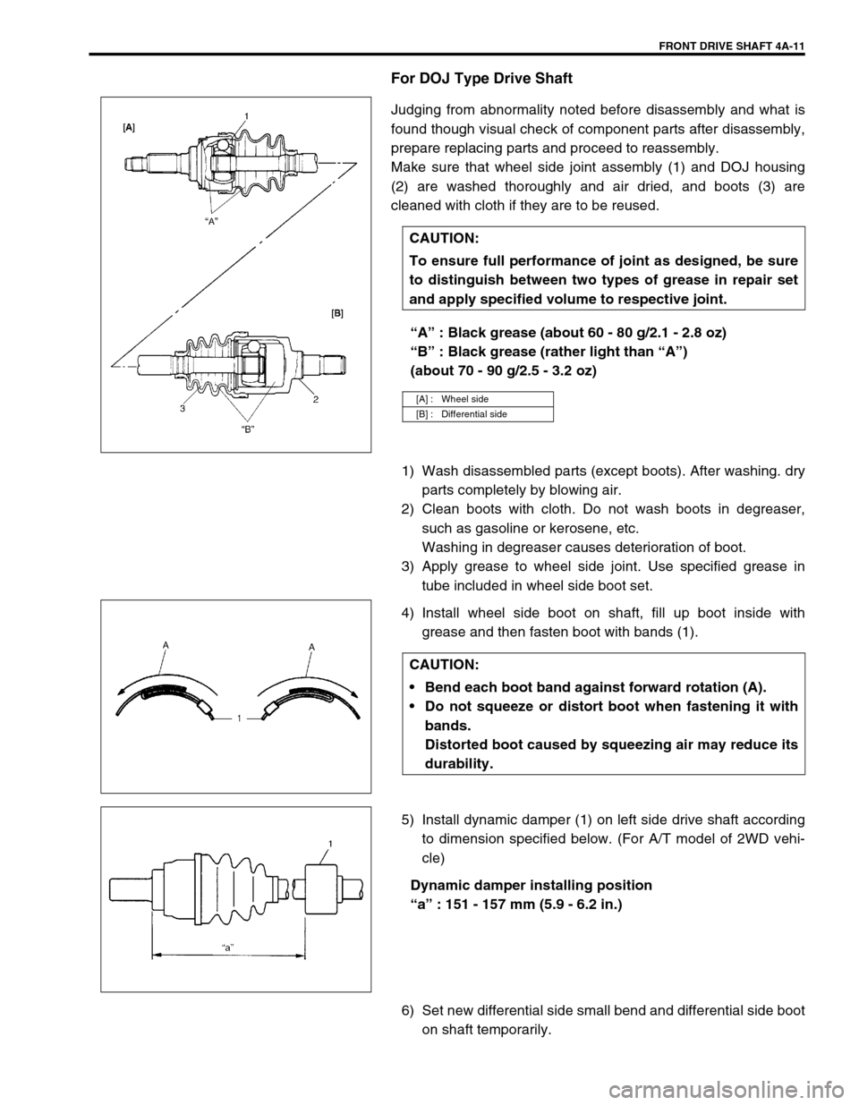
Make sure that wheel side joint assembly (1) and DOJ housing
(2) are washed thoroughly and air dried, and boots (3) are
cleaned with cloth if they are to be reused.
“A” : Black grease (about 60 - 80 g/2.1 - 2.8 oz)
“B” : Black grease (rather light than “A”)
(about 70 - 90 g/2.5 - 3.2 oz)
1) Wash disassembled parts (except boots). After washing. dry
parts completely by blowing air.
2) Clean boots with cloth. Do not wash boots in degreaser,
such as gasoline or kerosene, etc.
Washing in degreaser causes deterioration of boot.
3) Apply grease to wheel side joint. Use specified grease in
tube included in wheel side boot set.
4) Install wheel side boot on shaft, fill up boot inside with
grease and then fasten boot with bands (1).
5) Install dynamic damper (1) on left side drive shaft according
to dimension specified below. (For A/T model of 2WD vehi-
cle)
Dynamic damper installing position
“a” : 151 - 157 mm (5.9 - 6.2 in.)
6) Set new differential side small bend and differential side boot
on shaft temporarily. CAUTION:
To ensure full performance of joint as designed, be sure
to distinguish between two types of grease in repair set
and apply specified volume to respective joint.
[A] : Wheel side
[B] : Differential side
CAUTION:
Bend each boot band against forward rotation (A).
Do not squeeze or distort boot when fastening it with
bands.
Distorted boot caused by squeezing air may reduce its
durability.
Page 265 of 698
4A-12 FRONT DRIVE SHAFT
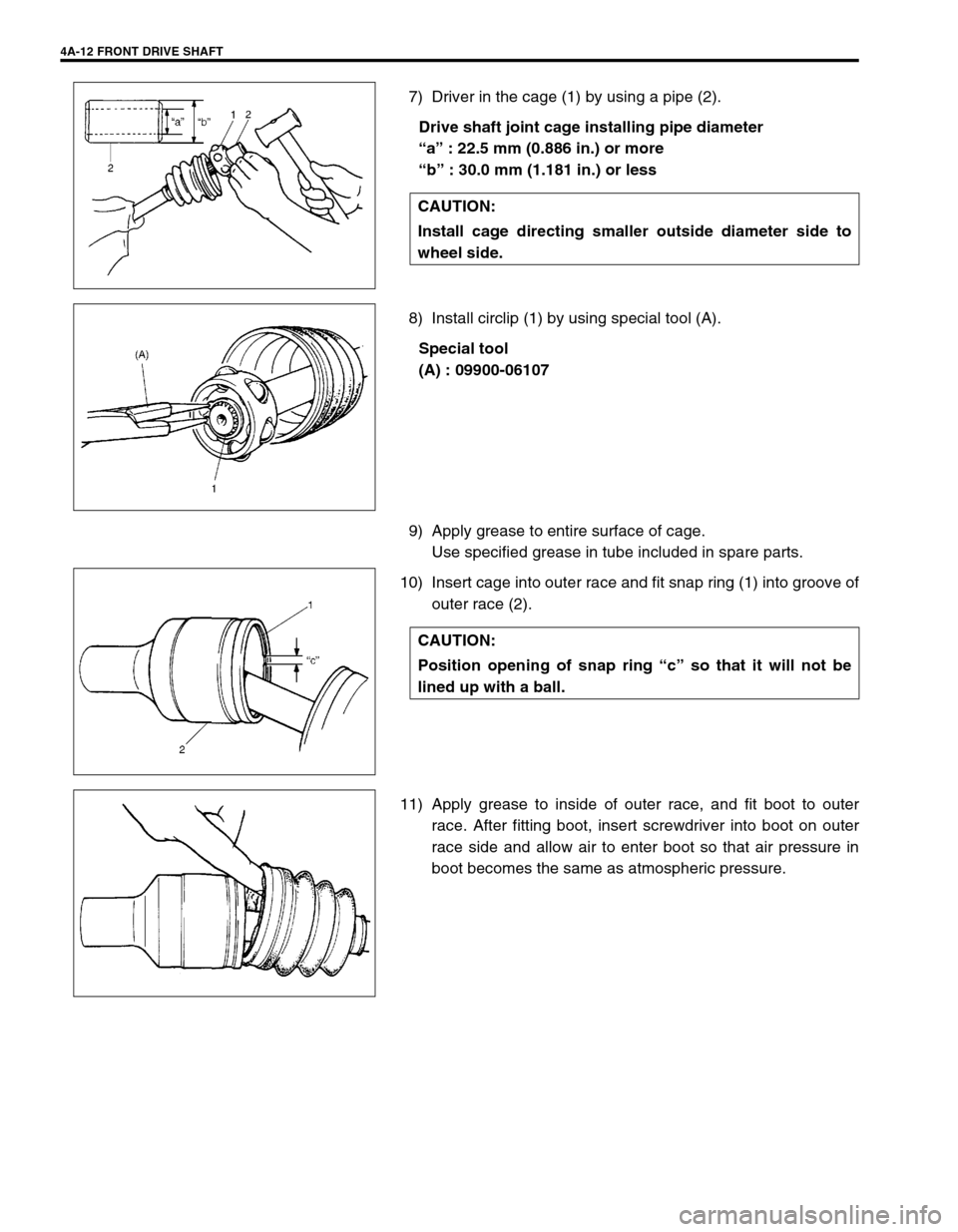
7) Driver in the cage (1) by using a pipe (2).
Drive shaft joint cage installing pipe diameter
“a” : 22.5 mm (0.886 in.) or more
“b” : 30.0 mm (1.181 in.) or less
8) Install circlip (1) by using special tool (A).
Special tool
(A) : 09900-06107
9) Apply grease to entire surface of cage.
Use specified grease in tube included in spare parts.
10) Insert cage into outer race and fit snap ring (1) into groove of
outer race (2).
11) Apply grease to inside of outer race, and fit boot to outer
race. After fitting boot, insert screwdriver into boot on outer
race side and allow air to enter boot so that air pressure in
boot becomes the same as atmospheric pressure. CAUTION:
Install cage directing smaller outside diameter side to
wheel side.
CAUTION:
Position opening of snap ring “c” so that it will not be
lined up with a ball.
Page 266 of 698
FRONT DRIVE SHAFT 4A-13
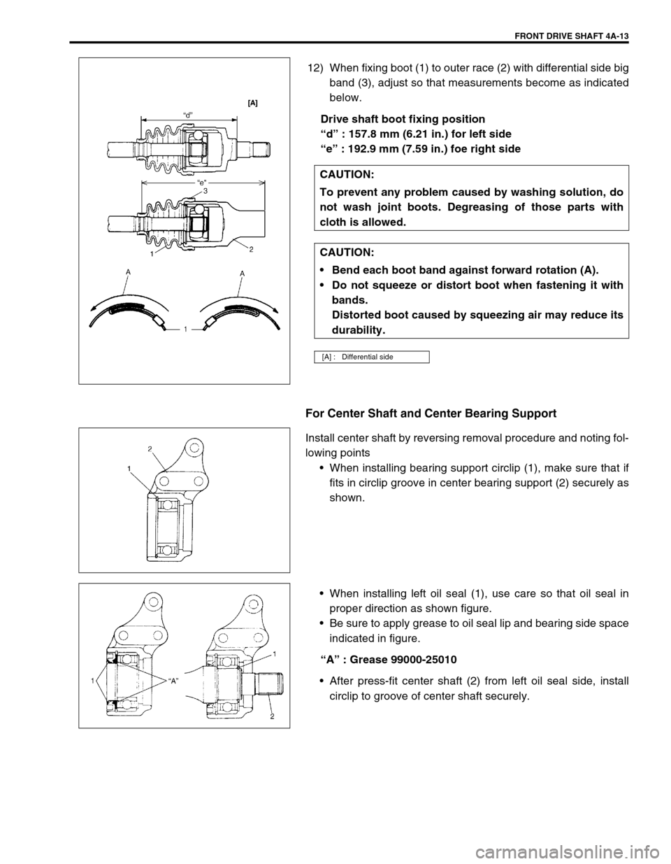
12) When fixing boot (1) to outer race (2) with differential side big
band (3), adjust so that measurements become as indicated
below.
Drive shaft boot fixing position
“d” : 157.8 mm (6.21 in.) for left side
“e” : 192.9 mm (7.59 in.) foe right side
For Center Shaft and Center Bearing Support
Install center shaft by reversing removal procedure and noting fol-
lowing points
When installing bearing support circlip (1), make sure that if
fits in circlip groove in center bearing support (2) securely as
shown.
When installing left oil seal (1), use care so that oil seal in
proper direction as shown figure.
Be sure to apply grease to oil seal lip and bearing side space
indicated in figure.
“A” : Grease 99000-25010
After press-fit center shaft (2) from left oil seal side, install
circlip to groove of center shaft securely. CAUTION:
To prevent any problem caused by washing solution, do
not wash joint boots. Degreasing of those parts with
cloth is allowed.
CAUTION:
Bend each boot band against forward rotation (A).
Do not squeeze or distort boot when fastening it with
bands.
Distorted boot caused by squeezing air may reduce its
durability.
[A] : Differential side
Page 267 of 698
4A-14 FRONT DRIVE SHAFT
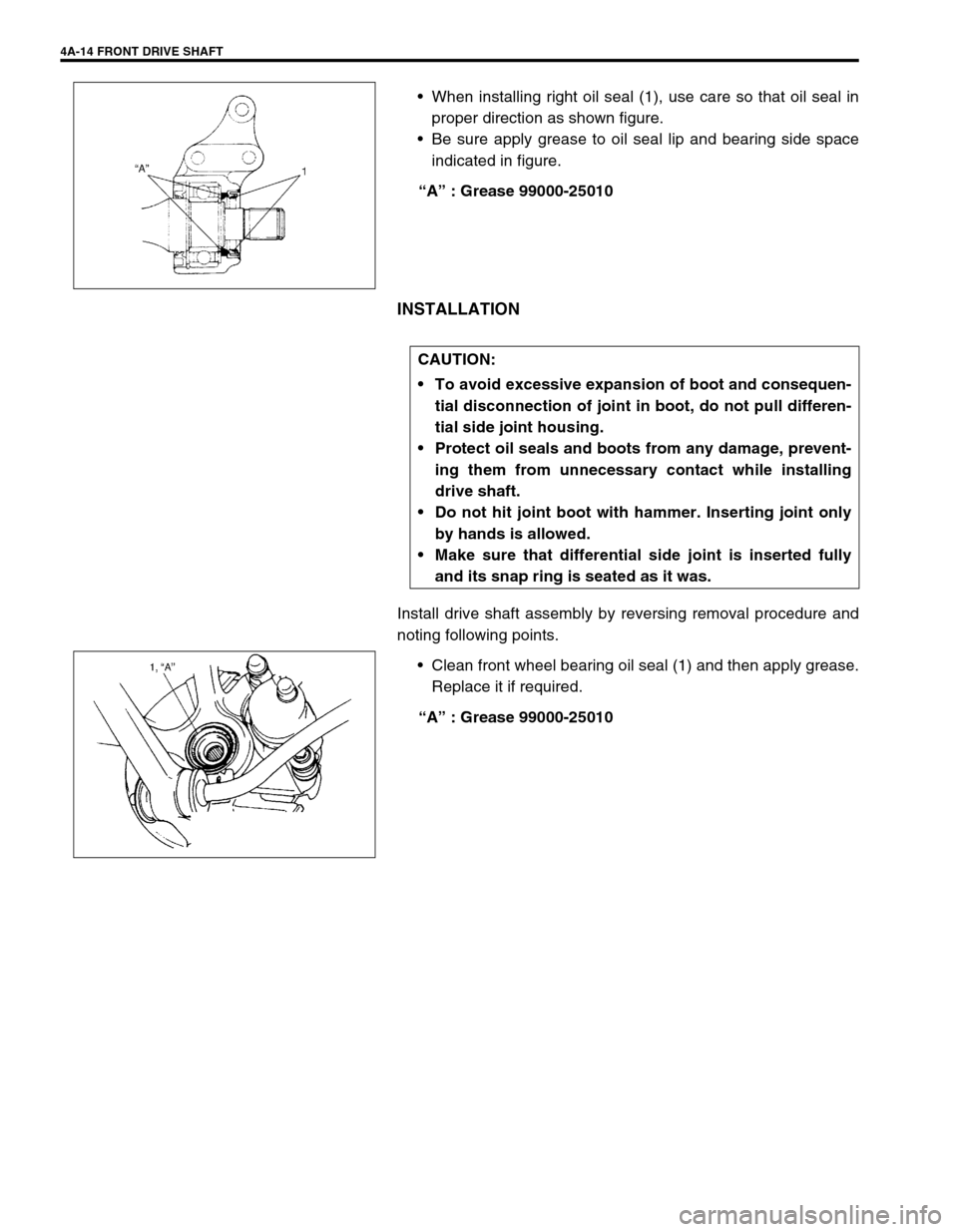
When installing right oil seal (1), use care so that oil seal in
proper direction as shown figure.
Be sure apply grease to oil seal lip and bearing side space
indicated in figure.
“A” : Grease 99000-25010
INSTALLATION
Install drive shaft assembly by reversing removal procedure and
noting following points.
Clean front wheel bearing oil seal (1) and then apply grease.
Replace it if required.
“A” : Grease 99000-25010
CAUTION:
To avoid excessive expansion of boot and consequen-
tial disconnection of joint in boot, do not pull differen-
tial side joint housing.
Protect oil seals and boots from any damage, prevent-
ing them from unnecessary contact while installing
drive shaft.
Do not hit joint boot with hammer. Inserting joint only
by hands is allowed.
Make sure that differential side joint is inserted fully
and its snap ring is seated as it was.
Page 268 of 698
FRONT DRIVE SHAFT 4A-15
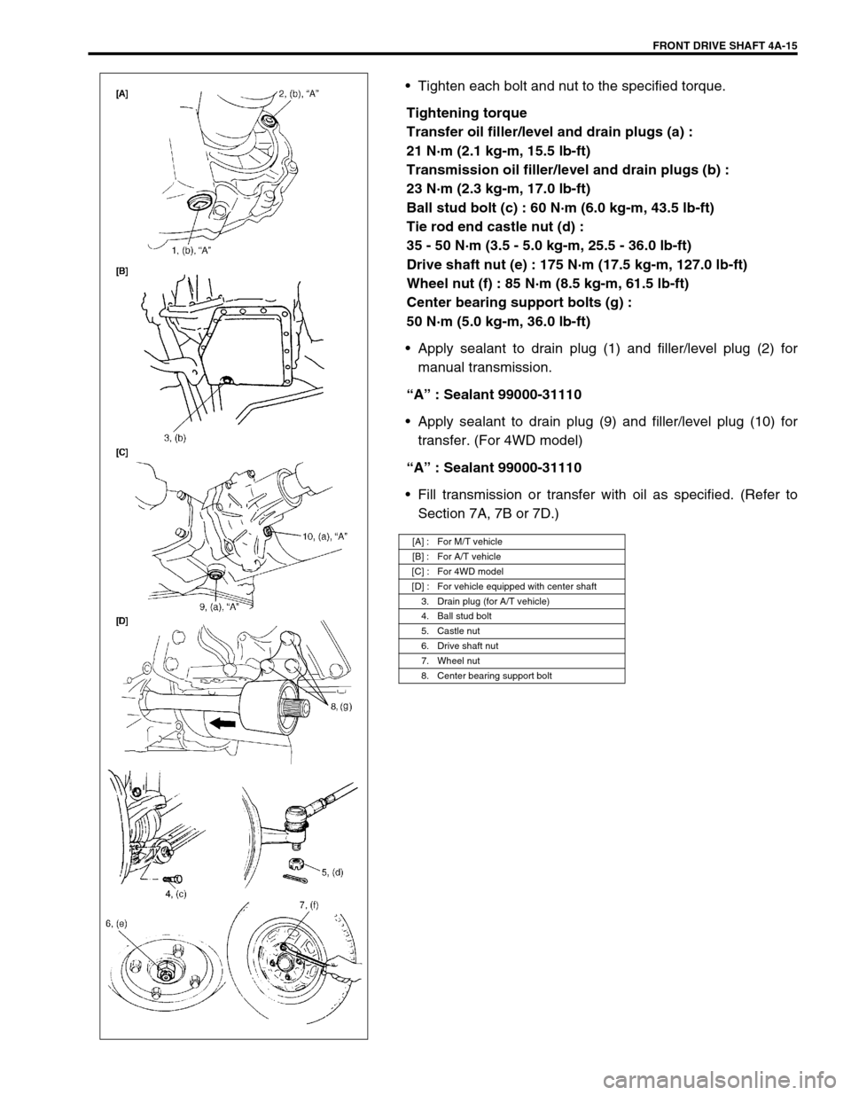
Tighten each bolt and nut to the specified torque.
Tightening torque
Transfer oil filler/level and drain plugs (a) :
21 N·m (2.1 kg-m, 15.5 lb-ft)
Transmission oil filler/level and drain plugs (b) :
23 N·m (2.3 kg-m, 17.0 lb-ft)
Ball stud bolt (c) : 60 N·m (6.0 kg-m, 43.5 lb-ft)
Tie rod end castle nut (d) :
35 - 50 N·m (3.5 - 5.0 kg-m, 25.5 - 36.0 lb-ft)
Drive shaft nut (e) : 175 N·m (17.5 kg-m, 127.0 lb-ft)
Wheel nut (f) : 85 N·m (8.5 kg-m, 61.5 lb-ft)
Center bearing support bolts (g) :
50 N·m (5.0 kg-m, 36.0 lb-ft)
Apply sealant to drain plug (1) and filler/level plug (2) for
manual transmission.
“A” : Sealant 99000-31110
Apply sealant to drain plug (9) and filler/level plug (10) for
transfer. (For 4WD model)
“A” : Sealant 99000-31110
Fill transmission or transfer with oil as specified. (Refer to
Section 7A, 7B or 7D.)
[A] : For M/T vehicle
[B] : For A/T vehicle
[C] : For 4WD model
[D] : For vehicle equipped with center shaft
3. Drain plug (for A/T vehicle)
4. Ball stud bolt
5. Castle nut
6. Drive shaft nut
7. Wheel nut
8. Center bearing support bolt
Page 269 of 698
4A-16 FRONT DRIVE SHAFT
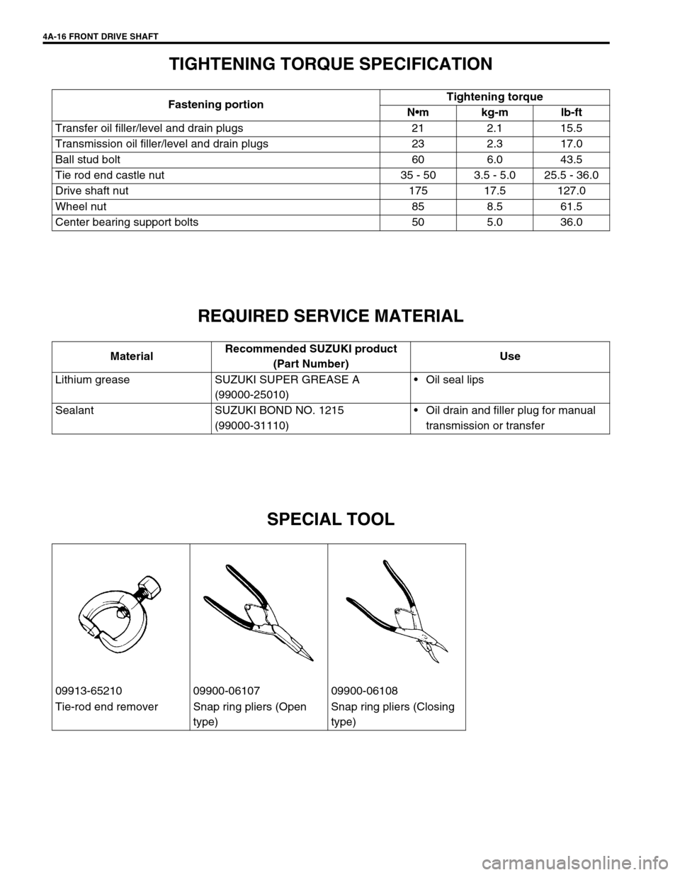
TIGHTENING TORQUE SPECIFICATION
REQUIRED SERVICE MATERIAL
SPECIAL TOOL
Fastening portionTightening torque
Nm kg-m lb-ft
Transfer oil filler/level and drain plugs 21 2.1 15.5
Transmission oil filler/level and drain plugs 23 2.3 17.0
Ball stud bolt 60 6.0 43.5
Tie rod end castle nut 35 - 50 3.5 - 5.0 25.5 - 36.0
Drive shaft nut 175 17.5 127.0
Wheel nut 85 8.5 61.5
Center bearing support bolts 50 5.0 36.0
MaterialRecommended SUZUKI product
(Part Number)Use
Lithium grease SUZUKI SUPER GREASE A
(99000-25010)Oil seal lips
Sealant SUZUKI BOND NO. 1215
(99000-31110)Oil drain and filler plug for manual
transmission or transfer
09913-65210 09900-06107 09900-06108
Tie-rod end remover Snap ring pliers (Open
type)Snap ring pliers (Closing
type)
Page 270 of 698
PROPELLER SHAFTS 4B-1
6F1
6F2
6G
6H
6K
7A
7A1
7B1
7C1
7D
7E
7F
4B
8D
8E
9
10
10A
10B
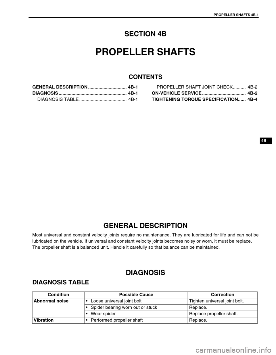
SECTION 4B
PROPELLER SHAFTS
CONTENTS
GENERAL DESCRIPTION .............................. 4B-1
DIAGNOSIS ..................................................... 4B-1
DIAGNOSIS TABLE ..................................... 4B-1PROPELLER SHAFT JOINT CHECK.......... 4B-2
ON-VEHICLE SERVICE .................................. 4B-2
TIGHTENING TORQUE SPECIFICATION...... 4B-4
GENERAL DESCRIPTION
Most universal and constant velocity joints require no maintenance. They are lubricated for life and can not be
lubricated on the vehicle. If universal and constant velocity joints becomes noisy or worn, it must be replace.
The propeller shaft is a balanced unit. Handle it carefully so that balance can be maintained.
DIAGNOSIS
DIAGNOSIS TABLE
Condition Possible Cause Correction
Abnormal noise
Loose universal joint bolt Tighten universal joint bolt.
Spider bearing worn out or stuck Replace.
Wear spider Replace propeller shaft.
Vibration
Performed propeller shaft Replace.