turn signal SUZUKI SWIFT 2000 1.G RG413 Service Owner's Manual
[x] Cancel search | Manufacturer: SUZUKI, Model Year: 2000, Model line: SWIFT, Model: SUZUKI SWIFT 2000 1.GPages: 698, PDF Size: 16.01 MB
Page 657 of 698

6E1-36 ENGINE AND EMISSION CONTROL SYSTEM
OUTPUT SIGNALS OF THROTTLE VALVE OPENING
AND ENGINE COOLANT TEMP. (VEHICLE WITH A/T
ONLY)
THROTTLE VALVE OPENING SIGNAL INSPECTION
Check throttle valve opening (throttle position) signal referring to
step 1 of DTC P1700 (No.32 or 33) Flow Table in Section 7B. If
check result is not satisfactory, check each wire harness, circuit
connections and TP sensor.
ENGINE COOLANT TEMP. SIGNAL INSPECTION
Check engine coolant temp. signal referring to step 1 of DTC
P1705 (NO.51) Flow Table in Section 7B.
If check result is not satisfactory, check each wire harness, circuit
connection and ECT sensor.
EMISSION CONTROL SYSTEM
EGR SYSTEM
SYSTEM INSPECTION (USING SUZUKI SCAN TOOL)
1) Connect SUZUKI scan tool to DLC with ignition switch OFF.
2) Turn ignition switch ON and then select “DATA LIST” mode
on scan tool.
3) Make sure that vehicle condition is as following.
Vehicle speed = 0 km/h (0 KPH)
Engine speed ≤ 3000 rpm
4) Clear DTC by using “CLEAR INFO” mode.
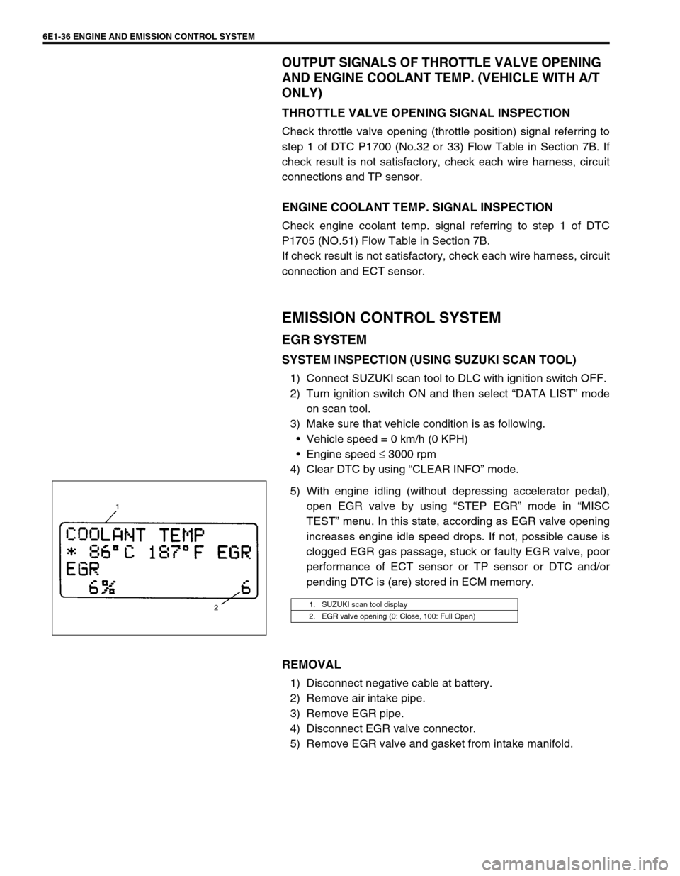
5) With engine idling (without depressing accelerator pedal),
open EGR valve by using “STEP EGR” mode in “MISC
TEST” menu. In this state, according as EGR valve opening
increases engine idle speed drops. If not, possible cause is
clogged EGR gas passage, stuck or faulty EGR valve, poor
performance of ECT sensor or TP sensor or DTC and/or
pending DTC is (are) stored in ECM memory.
REMOVAL
1) Disconnect negative cable at battery.
2) Remove air intake pipe.
3) Remove EGR pipe.
4) Disconnect EGR valve connector.
5) Remove EGR valve and gasket from intake manifold.
1. SUZUKI scan tool display
2. EGR valve opening (0: Close, 100: Full Open)
Page 664 of 698

6F1-2 IGNITION SYSTEM (ELECTRONIC IGNITION SYSTEM)
GENERAL DESCRIPTION
The ignition system is an electronic (distributorless) ignition system. Its consists of the parts as described below
and has an electronic ignition control system.
ECM
It detects the engine and vehicle conditions through the signals from the sensors, determines the most suit-
able ignition timing and time for electricity to flow to the primary coil and sends a signal to the ignitor (power
unit) in the ignition coil assembly.
Ignition coil assembly (including an igniter)
The ignition coil assembly has a built-in ignitor which turns ON and OFF the current flow to the primary coil
according to the signal from ECM. When the current flow to the primary coil is turned OFF, a high voltage is
induced in the secondary coil.
High tension cords and spark plugs.
CMP sensor (Camshaft position sensor) and CKP sensor (Crankshaft position sensor)
Using signals from these sensors, ECM identifies the specific cylinder whose piston is in the compression
stroke, detects the crank angle and adjusts initial ignition timing automatically.
TP sensor, ECT sensor, MAP sensor and other sensors/switches
Refer to Section 6E1 for details.
Although this ignition system does not have a distributor, it has two ignition coil assemblies (one is for No.1 and
No.4 spark plugs and the other is for No.2 and No.3 spark plugs). When an ignition signal is sent from ECM to
the ignitor in the ignition coil assembly for No.1 and No.4 spark plugs, a high voltage is induced in the secondary
coil and that passes through the high-tension cords and causes No.1 and No.4 spark plugs to spark simulta-
neously. Likewise, when an ignition signal is sent to the ignitor in the other ignition coil assembly, No.2 and No.3
spark plugs spark simultaneously.
SYSTEM COMPONENTS
1. ECM 6. MAP sensor 11. Transmission range switch (A/T)
2. Ignition coil assembly for No.1 and No.4 spark plugs 7. ECT sensor 12. High-tension cords
3. Ignition coil assembly for No.2 and No.3 spark plugs 8. IAT sensor 13. Monitor connector
4. CMP sensor 9. TP sensor 14. Knock sensor (if equipped)
5. CKP sensor 10. VSS 15. Data link connector