fog light SUZUKI SWIFT 2000 1.G RG413 Service Workshop Manual
[x] Cancel search | Manufacturer: SUZUKI, Model Year: 2000, Model line: SWIFT, Model: SUZUKI SWIFT 2000 1.GPages: 698, PDF Size: 16.01 MB
Page 401 of 698
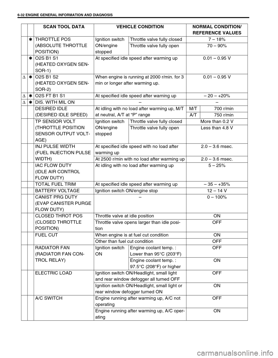
6-32 ENGINE GENERAL INFORMATION AND DIAGNOSIS
✱THROTTLE POS
(ABSOLUTE THROTTLE
POSITION)Ignition switch
ON/engine
stoppedThrottle valve fully closed 7 – 18%
Throttle valve fully open 70 – 90%
✱O2S B1 S1
(HEATED OXYGEN SEN-
SOR-1)At specified idle speed after warming up 0.01 – 0.95 V
∆✱O2S B1 S2
(HEATED OXYGEN SEN-
SOR-2)When engine is running at 2000 r/min. for 3
min or longer after warming up.0.01 – 0.95 V
∆✱O2S FT B1 S1 At specified idle speed after warning up– 20 – +20%
∆✱DIS. WITH MIL ON––
DESIRED IDLE
(DESIRED IDLE SPEED)At idling with no load after warming up, M/T
at neutral, A/T at “P” rangeM/T 700 r/min
A/T 750 r/min
TP SENSOR VOLT
(THROTTLE POSITION
SENSOR OUTPUT VOLT-
AGE)Ignition switch
ON/engine
stoppedThrottle valve fully closed More than 0.2 V
Throttle valve fully open Less than 4.8 V
INJ PULSE WIDTH
(FUEL INJECTION PULSE
WIDTH)At specified idle speed with no load after
warming up2.0 – 3.6 msec.
At 2500 r/min with no load after warming up 2.0 – 3.6 msec.
IAC FLOW DUTY
(IDLE AIR CONTROL
FLOW DUTY)At idling with no load after warming up 5 – 25%
TOTAL FUEL TRIM At specified idle speed after warming up– 35 – +35%
BATTERY VOLTAGE Ignition switch ON/engine stop 12 – 14 V
CANIST PRG DUTY
(EVAP CANISTER PURGE
FLOW DUTY)–0 – 100%
CLOSED THROT POS
(CLOSED THROTTLE
POSITION)Throttle valve at idle position ON
Throttle valve opens larger than idle posi-
tionOFF
FUEL CUT When engine is at fuel cut condition ON
Other than fuel cut condition OFF
RADIATOR FAN
(RADIATOR FAN CON-
TROL RELAY)Ignition switch
ONEngine coolant temp. :
Lower than 95°C (203°F)OFF
Engine coolant temp. :
97.5°C (208°F) or higherON
ELECTRIC LOAD Ignition switch ON/Headlight, small light
and rear window defogger all turned OFFOFF
Ignition switch ON/Headlight, small light or
rear window defogger turned ONON
A/C SWITCH Engine running after warming up, A/C not
operatingOFF
Engine running after warming up, A/C oper-
atingON SCAN TOOL DATA VEHICLE CONDITION NORMAL CONDITION/
REFERENCE VALUES
Page 404 of 698
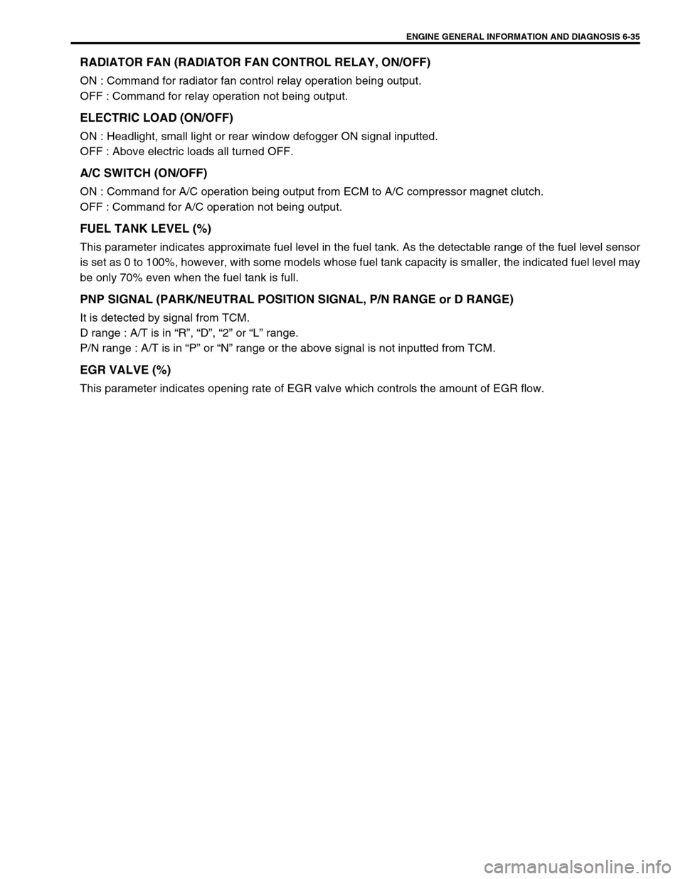
ENGINE GENERAL INFORMATION AND DIAGNOSIS 6-35
RADIATOR FAN (RADIATOR FAN CONTROL RELAY, ON/OFF)
ON : Command for radiator fan control relay operation being output.
OFF : Command for relay operation not being output.
ELECTRIC LOAD (ON/OFF)
ON : Headlight, small light or rear window defogger ON signal inputted.
OFF : Above electric loads all turned OFF.
A/C SWITCH (ON/OFF)
ON : Command for A/C operation being output from ECM to A/C compressor magnet clutch.
OFF : Command for A/C operation not being output.
FUEL TANK LEVEL (%)
This parameter indicates approximate fuel level in the fuel tank. As the detectable range of the fuel level sensor
is set as 0 to 100%, however, with some models whose fuel tank capacity is smaller, the indicated fuel level may
be only 70% even when the fuel tank is full.
PNP SIGNAL (PARK/NEUTRAL POSITION SIGNAL, P/N RANGE or D RANGE)
It is detected by signal from TCM.
D range : A/T is in “R”, “D”, “2” or “L” range.
P/N range : A/T is in “P” or “N” range or the above signal is not inputted from TCM.
EGR VALVE (%)
This parameter indicates opening rate of EGR valve which controls the amount of EGR flow.
Page 406 of 698
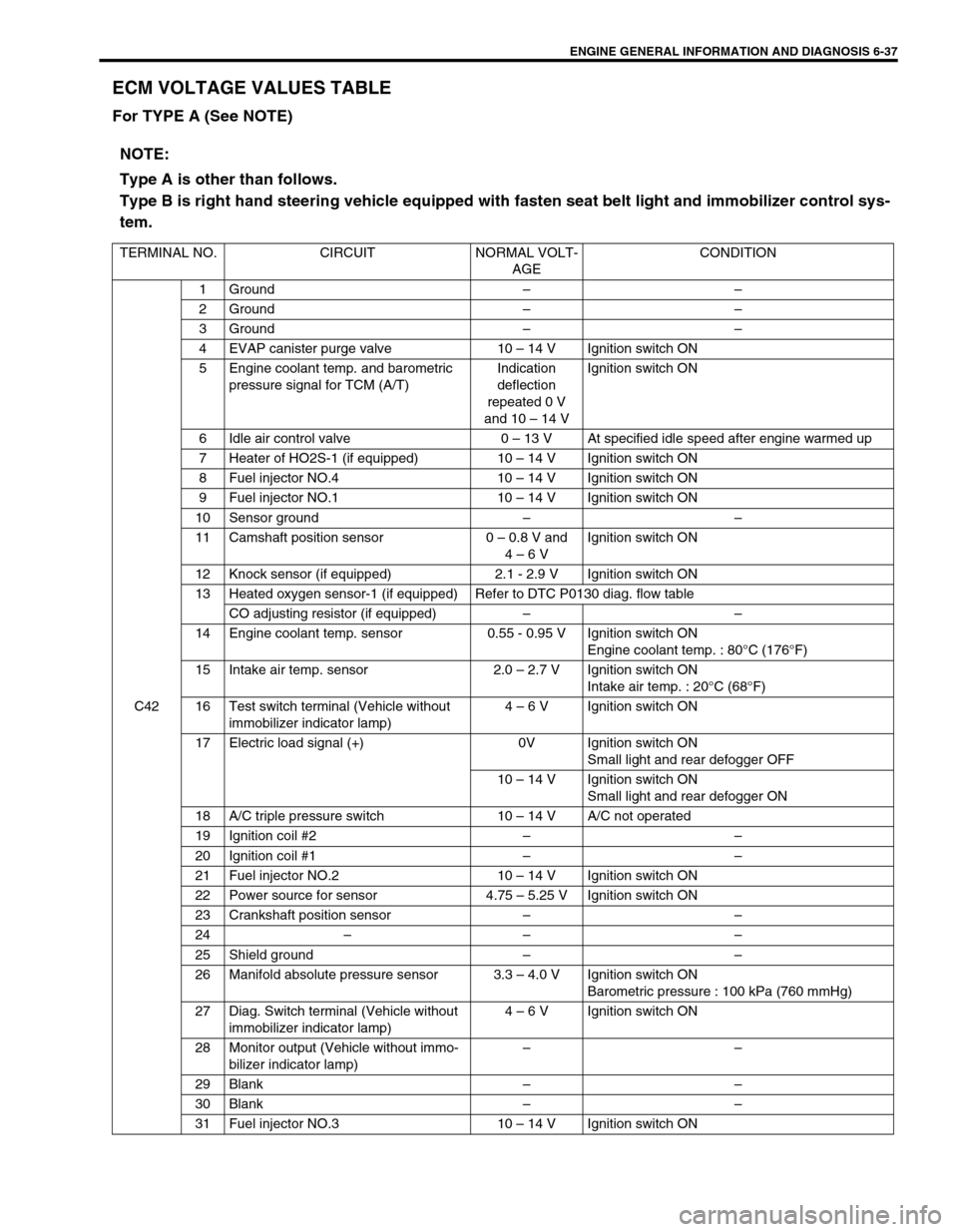
ENGINE GENERAL INFORMATION AND DIAGNOSIS 6-37
ECM VOLTAGE VALUES TABLE
For TYPE A (See NOTE)
NOTE:
Type A is other than follows.
Type B is right hand steering vehicle equipped with fasten seat belt light and immobilizer control sys-
tem.
TERMINAL NO. CIRCUIT NORMAL VOLT-
AGECONDITION
C421 Ground––
2 Ground––
3 Ground––
4 EVAP canister purge valve 10 – 14 V Ignition switch ON
5 Engine coolant temp. and barometric
pressure signal for TCM (A/T)Indication
deflection
repeated 0 V
and 10 – 14 VIgnition switch ON
6 Idle air control valve 0 – 13 V At specified idle speed after engine warmed up
7 Heater of HO2S-1 (if equipped) 10 – 14 V Ignition switch ON
8 Fuel injector NO.4 10 – 14 V Ignition switch ON
9 Fuel injector NO.1 10 – 14 V Ignition switch ON
10 Sensor ground––
11 Camshaft position sensor 0 – 0.8 V and
4 – 6 VIgnition switch ON
12 Knock sensor (if equipped) 2.1 - 2.9 V Ignition switch ON
13 Heated oxygen sensor-1 (if equipped) Refer to DTC P0130 diag. flow table
CO adjusting resistor (if equipped)––
14 Engine coolant temp. sensor 0.55 - 0.95 V Ignition switch ON
Engine coolant temp. : 80°C (176°F)
15 Intake air temp. sensor 2.0 – 2.7 V Ignition switch ON
Intake air temp. : 20°C (68°F)
16 Test switch terminal (Vehicle without
immobilizer indicator lamp)4 – 6 V Ignition switch ON
17 Electric load signal (+) 0V Ignition switch ON
Small light and rear defogger OFF
10 – 14 V Ignition switch ON
Small light and rear defogger ON
18 A/C triple pressure switch 10 – 14 V A/C not operated
19 Ignition coil #2––
20 Ignition coil #1––
21 Fuel injector NO.2 10 – 14 V Ignition switch ON
22 Power source for sensor 4.75 – 5.25 V Ignition switch ON
23 Crankshaft position sensor––
24–– –
25 Shield ground––
26 Manifold absolute pressure sensor 3.3 – 4.0 V Ignition switch ON
Barometric pressure : 100 kPa (760 mmHg)
27 Diag. Switch terminal (Vehicle without
immobilizer indicator lamp)4 – 6 V Ignition switch ON
28 Monitor output (Vehicle without immo-
bilizer indicator lamp)––
29 Blank––
30 Blank––
31 Fuel injector NO.3 10 – 14 V Ignition switch ON
Page 410 of 698
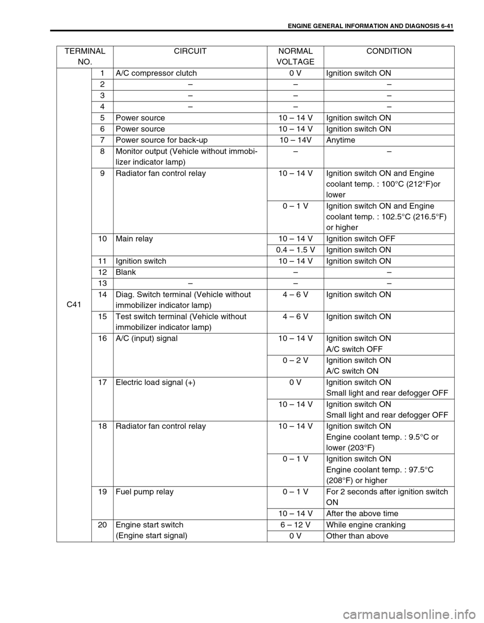
ENGINE GENERAL INFORMATION AND DIAGNOSIS 6-41
TERMINAL
NO.CIRCUIT NORMAL
VOLTAGECONDITION
C411 A/C compressor clutch 0 V Ignition switch ON
2–––
3–––
4–––
5 Power source 10 – 14 V Ignition switch ON
6 Power source 10 – 14 V Ignition switch ON
7 Power source for back-up 10 – 14V Anytime
8 Monitor output (Vehicle without immobi-
lizer indicator lamp)––
9 Radiator fan control relay 10 – 14 V Ignition switch ON and Engine
coolant temp. : 100°C (212°F)or
lower
0 – 1 V Ignition switch ON and Engine
coolant temp. : 102.5°C (216.5°F)
or higher
10 Main relay 10 – 14 V Ignition switch OFF
0.4 – 1.5 V Ignition switch ON
11 Ignition switch 10 – 14 V Ignition switch ON
12 Blank––
13–––
14 Diag. Switch terminal (Vehicle without
immobilizer indicator lamp)4 – 6 V Ignition switch ON
15 Test switch terminal (Vehicle without
immobilizer indicator lamp)4 – 6 V Ignition switch ON
16 A/C (input) signal 10 – 14 V Ignition switch ON
A/C switch OFF
0 – 2 V Ignition switch ON
A/C switch ON
17 Electric load signal (+) 0 V Ignition switch ON
Small light and rear defogger OFF
10 – 14 V Ignition switch ON
Small light and rear defogger OFF
18 Radiator fan control relay 10 – 14 V Ignition switch ON
Engine coolant temp. : 9.5°C or
lower (203°F)
0 – 1 V Ignition switch ON
Engine coolant temp. : 97.5°C
(208°F) or higher
19 Fuel pump relay 0 – 1 V For 2 seconds after ignition switch
ON
10 – 14 V After the above time
20 Engine start switch
(Engine start signal)6 – 12 V While engine cranking
0 V Other than above
Page 496 of 698
![SUZUKI SWIFT 2000 1.G RG413 Service Workshop Manual ENGINE GENERAL INFORMATION AND DIAGNOSIS 6-127
Fig. 1 for Step 2
Fig. 2 for Step 3
Table 1 for Step 2 and 3
[A] : When using SUZUKI scan tool:
[ A]
[A] : When not using SUZUKI scan tool:
[a] : Case of SUZUKI SWIFT 2000 1.G RG413 Service Workshop Manual ENGINE GENERAL INFORMATION AND DIAGNOSIS 6-127
Fig. 1 for Step 2
Fig. 2 for Step 3
Table 1 for Step 2 and 3
[A] : When using SUZUKI scan tool:
[ A]
[A] : When not using SUZUKI scan tool:
[a] : Case of](/img/20/7606/w960_7606-495.png)
ENGINE GENERAL INFORMATION AND DIAGNOSIS 6-127
Fig. 1 for Step 2
Fig. 2 for Step 3
Table 1 for Step 2 and 3
[A] : When using SUZUKI scan tool:
[ A]
[A] : When not using SUZUKI scan tool:
[a] : Case of TYPE A is shown (See NOTE)
[b] : Case of TYPE B is shown (See NOTE)
Scan tool or voltmeter
SUZUKI
SCAN TOOLVOLTAGE
AT C42-17VOLTAGE
AT G02-13
Ignition switch ON, Small
light, heater blower fan and
rear defogger all turnedOFF OFF 0V 10 – 14V
ON ON 10 – 14V 0V
Page 629 of 698
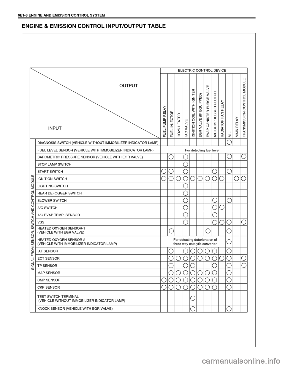
6E1-8 ENGINE AND EMISSION CONTROL SYSTEM
ENGINE & EMISSION CONTROL INPUT/OUTPUT TABLE
INPUTOUTPUT
ELECTRIC CONTROL DEVICE
FUEL LEVEL SENSOR (VEHICLE WITH IMMOBILIZER INDICATOR LAMP) For detecting fuel level DIAGNOSIS SWITCH (VEHICLE WITHOUT IMMOBILIZER INDICATOR LAMP)
BAROMETRIC PRESSURE SENSOR (VEHICLE WITH EGR VALVE)
STOP LAMP SWITCH
START SWITCH
IGNITION SWITCH
LIGHTING SWITCH
REAR DEFOGGER SWITCH
BLOWER SWITCH
A/C SWITCH
A/C EVAP TEMP. SENSOR
VSS
HEATED OXYGEN SENSOR-1
(VEHICLE WITH EGR VALVE)
HEATED OXYGEN SENSOR-2
(VEHICLE WITH IMMOBILIZER INDICATOR LAMP)For detecting deterioration of
three way catalytic convertor
IAT SENSOR
ECT SENSOR
TP SENSOR
MAP SENSOR
CMP SENSOR
CKP SENSOR
TEST SWITCH TERMINAL
(VEHICLE WITHOUT IMMOBILIZER INDICATOR LAMP)
KNOCK SENSOR (VEHICLE WITH EGR VALVE)
FUEL PUMP RELAY
FUEL INJECTOR
HO2S HEATER
IAC VALVE
IGNITION COIL WITH IGNITER
EGR VALVE (IF EQUIPPED)
EVAP CANISTER PURGE VALVE
A/C COMPRESSOR CLUTCH
RADIATOR FAN RELAY
MIL
MAIN RELAY
TRANSMISSION CONTROL MODULE SIGNAL FROM SENSOR, SWITCH AND CONTROL MODULE
Page 631 of 698
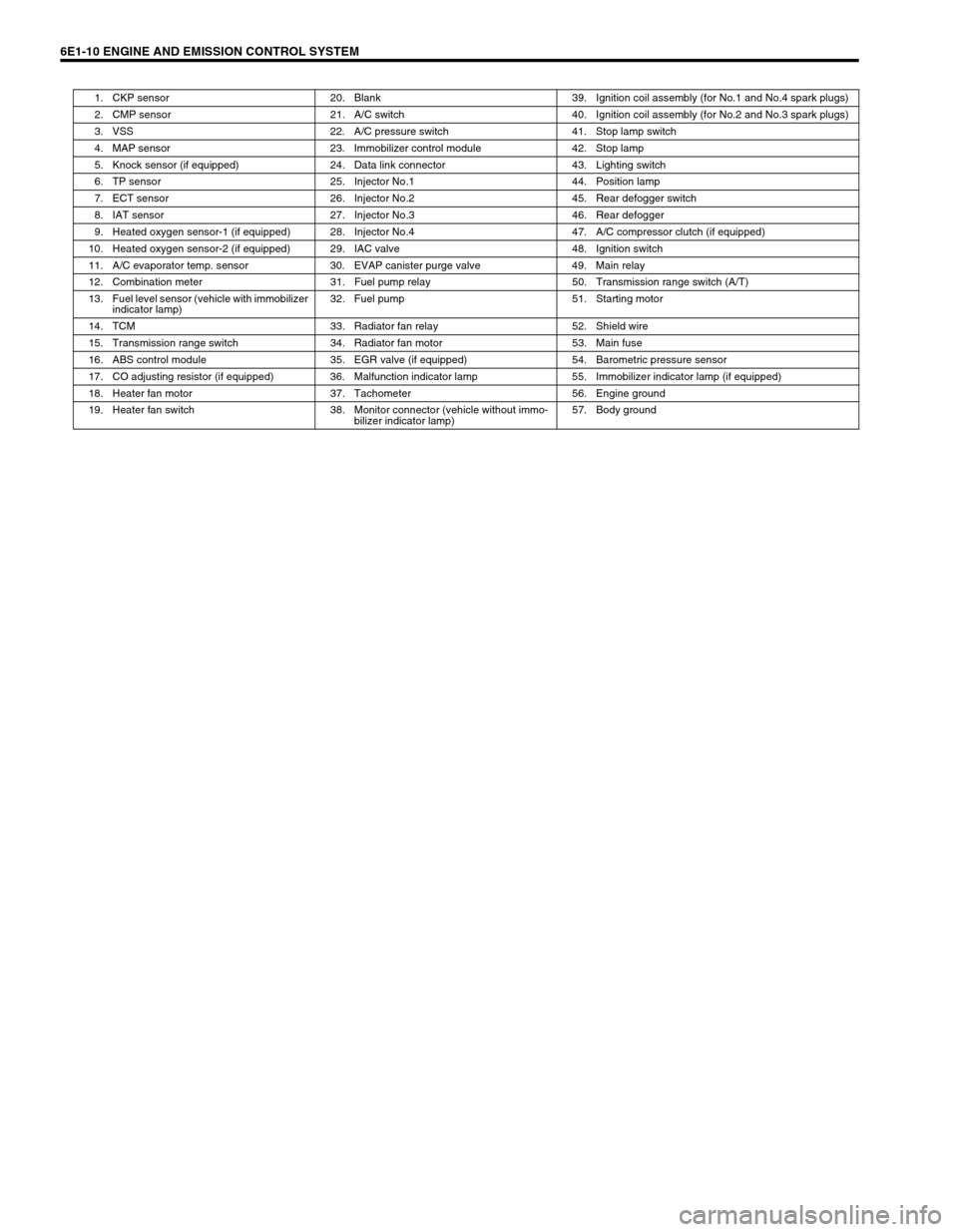
6E1-10 ENGINE AND EMISSION CONTROL SYSTEM
1. CKP sensor 20. Blank 39. Ignition coil assembly (for No.1 and No.4 spark plugs)
2. CMP sensor 21. A/C switch 40. Ignition coil assembly (for No.2 and No.3 spark plugs)
3. VSS 22. A/C pressure switch 41. Stop lamp switch
4. MAP sensor 23. Immobilizer control module 42. Stop lamp
5. Knock sensor (if equipped) 24. Data link connector 43. Lighting switch
6. TP sensor 25. Injector No.1 44. Position lamp
7. ECT sensor 26. Injector No.2 45. Rear defogger switch
8. IAT sensor 27. Injector No.3 46. Rear defogger
9. Heated oxygen sensor-1 (if equipped) 28. Injector No.4 47. A/C compressor clutch (if equipped)
10. Heated oxygen sensor-2 (if equipped) 29. IAC valve 48. Ignition switch
11. A/C evaporator temp. sensor 30. EVAP canister purge valve 49. Main relay
12. Combination meter 31. Fuel pump relay 50. Transmission range switch (A/T)
13. Fuel level sensor (vehicle with immobilizer
indicator lamp)32. Fuel pump 51. Starting motor
14. TCM 33. Radiator fan relay 52. Shield wire
15. Transmission range switch 34. Radiator fan motor 53. Main fuse
16. ABS control module 35. EGR valve (if equipped) 54. Barometric pressure sensor
17. CO adjusting resistor (if equipped) 36. Malfunction indicator lamp 55. Immobilizer indicator lamp (if equipped)
18. Heater fan motor 37. Tachometer 56. Engine ground
19. Heater fan switch 38. Monitor connector (vehicle without immo-
bilizer indicator lamp)57. Body ground
Page 633 of 698
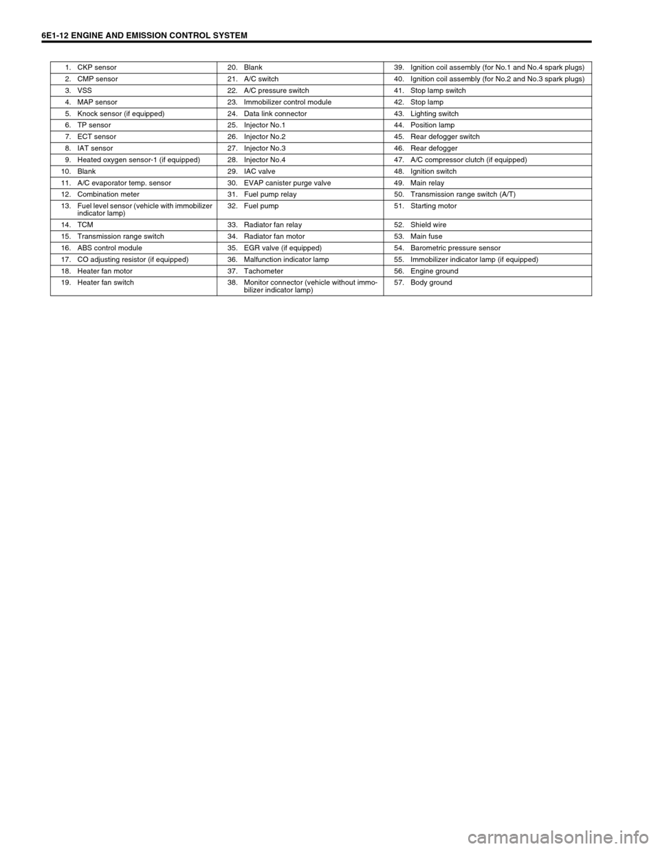
6E1-12 ENGINE AND EMISSION CONTROL SYSTEM
1. CKP sensor 20. Blank 39. Ignition coil assembly (for No.1 and No.4 spark plugs)
2. CMP sensor 21. A/C switch 40. Ignition coil assembly (for No.2 and No.3 spark plugs)
3. VSS 22. A/C pressure switch 41. Stop lamp switch
4. MAP sensor 23. Immobilizer control module 42. Stop lamp
5. Knock sensor (if equipped) 24. Data link connector 43. Lighting switch
6. TP sensor 25. Injector No.1 44. Position lamp
7. ECT sensor 26. Injector No.2 45. Rear defogger switch
8. IAT sensor 27. Injector No.3 46. Rear defogger
9. Heated oxygen sensor-1 (if equipped) 28. Injector No.4 47. A/C compressor clutch (if equipped)
10. Blank 29. IAC valve 48. Ignition switch
11. A/C evaporator temp. sensor 30. EVAP canister purge valve 49. Main relay
12. Combination meter 31. Fuel pump relay 50. Transmission range switch (A/T)
13. Fuel level sensor (vehicle with immobilizer
indicator lamp)32. Fuel pump 51. Starting motor
14. TCM 33. Radiator fan relay 52. Shield wire
15. Transmission range switch 34. Radiator fan motor 53. Main fuse
16. ABS control module 35. EGR valve (if equipped) 54. Barometric pressure sensor
17. CO adjusting resistor (if equipped) 36. Malfunction indicator lamp 55. Immobilizer indicator lamp (if equipped)
18. Heater fan motor 37. Tachometer 56. Engine ground
19. Heater fan switch 38. Monitor connector (vehicle without immo-
bilizer indicator lamp)57. Body ground