rear brake SUZUKI SWIFT 2000 1.G RG413 Service Repair Manual
[x] Cancel search | Manufacturer: SUZUKI, Model Year: 2000, Model line: SWIFT, Model: SUZUKI SWIFT 2000 1.GPages: 698, PDF Size: 16.01 MB
Page 332 of 698
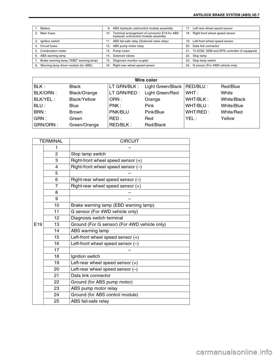
ANTILOCK BRAKE SYSTEM (ABS) 5E-7
1. Battery 9. ABS hydraulic unit/control module assembly 17. Left-rear wheel speed sensor
2. Main fuses 10. Terminal arrangement of connector E19 for ABS
hydraulic unit/control module assembly18. Right-front wheel speed sensor
3. Ignition switch 11. ABS fail-safe relay (Solenoid valve relay) 19. Left-front wheel speed sensor
4. Circuit fuses 12. ABS pump motor relay 20. Data link connector
5. Combination meter 13. Pump motor 21. To ECM, SDM and EPS controller (if equipped)
6. ABS warning lamp 14. Solenoid valves 22. Stop lamp
7. Brake warning lamp (“EBD” warning lamp) 15. Diagnosis monitor coupler 23. Stop lamp switch
8. Warning lamp driver module (for ABS) 16. Right-rear wheel speed sensor 24. G sensor (For 4WD vehicle only)
Wire color
BLK : Black LT GRN/BLK : Light Green/Black RED/BLU : Red/Blue
BLK/ORN : Black/Orange LT GRN/RED : Light Green/Red WHT : White
BLK/YEL : Black/Yellow ORN : Orange WHT/BLK : White/Black
BLU : Blue PNK : Pink WHT/BLU : White/Blue
BRN : Brown PNK/BLU Pink/Blue WHT/RED : White/Red
GRN : Green RED : Red YEL : Yellow
GRN/ORN : Green/Orange RED/BLK : Red/Black
TERMINAL CIRCUIT
E191–
2 Stop lamp switch
3 Right-front wheel speed sensor (+)
4 Right-front wheel speed sensor (–)
5–
6 Right-rear wheel speed sensor (–)
7 Right-rear wheel speed sensor (+)
8–
9–
10 Brake warning lamp (EBD warning lamp)
11 G sensor (For 4WD vehicle only)
12 Diagnosis switch terminal
13 Ground (For G sensor) (For 4WD vehicle only)
14 ABS warning lamp
15 Left-front wheel speed sensor (+)
16 Left-front wheel speed sensor (–)
17–
18 Ignition switch
19 Left-rear wheel speed sensor (+)
20 Left-rear wheel speed sensor (–)
21 Data link connector
22 Ground (for ABS pump motor)
23 ABS pump motor relay
24 Ground (for ABS control module)
25 ABS fail-safe relay
Page 349 of 698
5E-24 ANTILOCK BRAKE SYSTEM (ABS)
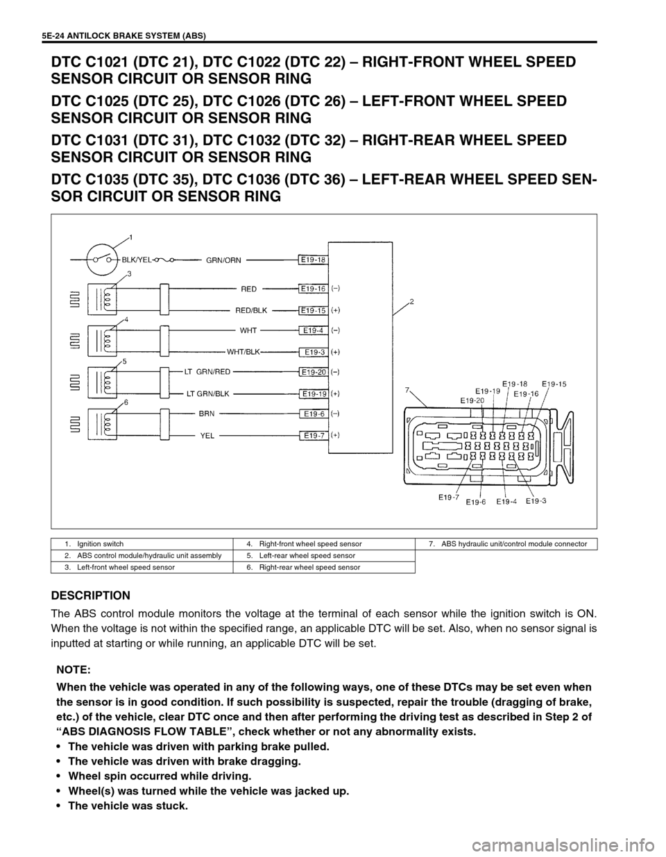
DTC C1021 (DTC 21), DTC C1022 (DTC 22) – RIGHT-FRONT WHEEL SPEED
SENSOR CIRCUIT OR SENSOR RING
DTC C1025 (DTC 25), DTC C1026 (DTC 26) – LEFT-FRONT WHEEL SPEED
SENSOR CIRCUIT OR SENSOR RING
DTC C1031 (DTC 31), DTC C1032 (DTC 32) – RIGHT-REAR WHEEL SPEED
SENSOR CIRCUIT OR SENSOR RING
DTC C1035 (DTC 35), DTC C1036 (DTC 36) – LEFT-REAR WHEEL SPEED SEN-
SOR CIRCUIT OR SENSOR RING
DESCRIPTION
The ABS control module monitors the voltage at the terminal of each sensor while the ignition switch is ON.
When the voltage is not within the specified range, an applicable DTC will be set. Also, when no sensor signal is
inputted at starting or while running, an applicable DTC will be set.
1. Ignition switch 4. Right-front wheel speed sensor 7. ABS hydraulic unit/control module connector
2. ABS control module/hydraulic unit assembly 5. Left-rear wheel speed sensor
3. Left-front wheel speed sensor 6. Right-rear wheel speed sensor
NOTE:
When the vehicle was operated in any of the following ways, one of these DTCs may be set even when
the sensor is in good condition. If such possibility is suspected, repair the trouble (dragging of brake,
etc.) of the vehicle, clear DTC once and then after performing the driving test as described in Step 2 of
“ABS DIAGNOSIS FLOW TABLE”, check whether or not any abnormality exists.
The vehicle was driven with parking brake pulled.
The vehicle was driven with brake dragging.
Wheel spin occurred while driving.
Wheel(s) was turned while the vehicle was jacked up.
The vehicle was stuck.
Page 350 of 698
ANTILOCK BRAKE SYSTEM (ABS) 5E-25
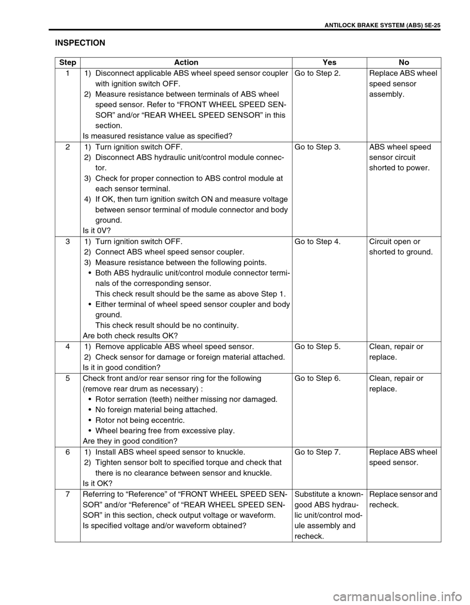
INSPECTION
Step Action Yes No
1 1) Disconnect applicable ABS wheel speed sensor coupler
with ignition switch OFF.
2) Measure resistance between terminals of ABS wheel
speed sensor. Refer to “FRONT WHEEL SPEED SEN-
SOR” and/or “REAR WHEEL SPEED SENSOR” in this
section.
Is measured resistance value as specified?Go to Step 2. Replace ABS wheel
speed sensor
assembly.
2 1) Turn ignition switch OFF.
2) Disconnect ABS hydraulic unit/control module connec-
tor.
3) Check for proper connection to ABS control module at
each sensor terminal.
4) If OK, then turn ignition switch ON and measure voltage
between sensor terminal of module connector and body
ground.
Is it 0V?Go to Step 3. ABS wheel speed
sensor circuit
shorted to power.
3 1) Turn ignition switch OFF.
2) Connect ABS wheel speed sensor coupler.
3) Measure resistance between the following points.
Both ABS hydraulic unit/control module connector termi-
nals of the corresponding sensor.
This check result should be the same as above Step 1.
Either terminal of wheel speed sensor coupler and body
ground.
This check result should be no continuity.
Are both check results OK?Go to Step 4. Circuit open or
shorted to ground.
4 1) Remove applicable ABS wheel speed sensor.
2) Check sensor for damage or foreign material attached.
Is it in good condition?Go to Step 5. Clean, repair or
replace.
5 Check front and/or rear sensor ring for the following
(remove rear drum as necessary) :
Rotor serration (teeth) neither missing nor damaged.
No foreign material being attached.
Rotor not being eccentric.
Wheel bearing free from excessive play.
Are they in good condition?Go to Step 6. Clean, repair or
replace.
6 1) Install ABS wheel speed sensor to knuckle.
2) Tighten sensor bolt to specified torque and check that
there is no clearance between sensor and knuckle.
Is it OK?Go to Step 7. Replace ABS wheel
speed sensor.
7 Referring to “Reference” of “FRONT WHEEL SPEED SEN-
SOR” and/or “Reference” of “REAR WHEEL SPEED SEN-
SOR” in this section, check output voltage or waveform.
Is specified voltage and/or waveform obtained?Substitute a known-
good ABS hydrau-
lic unit/control mod-
ule assembly and
recheck.Replace sensor and
recheck.
Page 351 of 698
5E-26 ANTILOCK BRAKE SYSTEM (ABS)
DTC C1041 (DTC 41) – RIGHT-FRONT INLET SOLENOID CIRCUIT
DTC C1045 (DTC 45) – LEFT-FRONT INLET SOLENOID CIRCUIT
DTC C1051 (DTC 51) – RIGHT-REAR INLET SOLENOID CIRCUIT
DTC C1055 (DTC 55) – LEFT-REAR INLET SOLENOID CIRCUIT
DTC C1042 (DTC 42) – RIGHT-FRONT OUTLET SOLENOID CIRCUIT
DTC C1046 (DTC 46) – LEFT-FRONT OUTLET SOLENOID CIRCUIT
DTC C1052 (DTC 52) – RIGHT-REAR OUTLET SOLENOID CIRCUIT
DTC C1056 (DTC 56) – LEFT-REAR OUTLET SOLENOID CIRCUIT
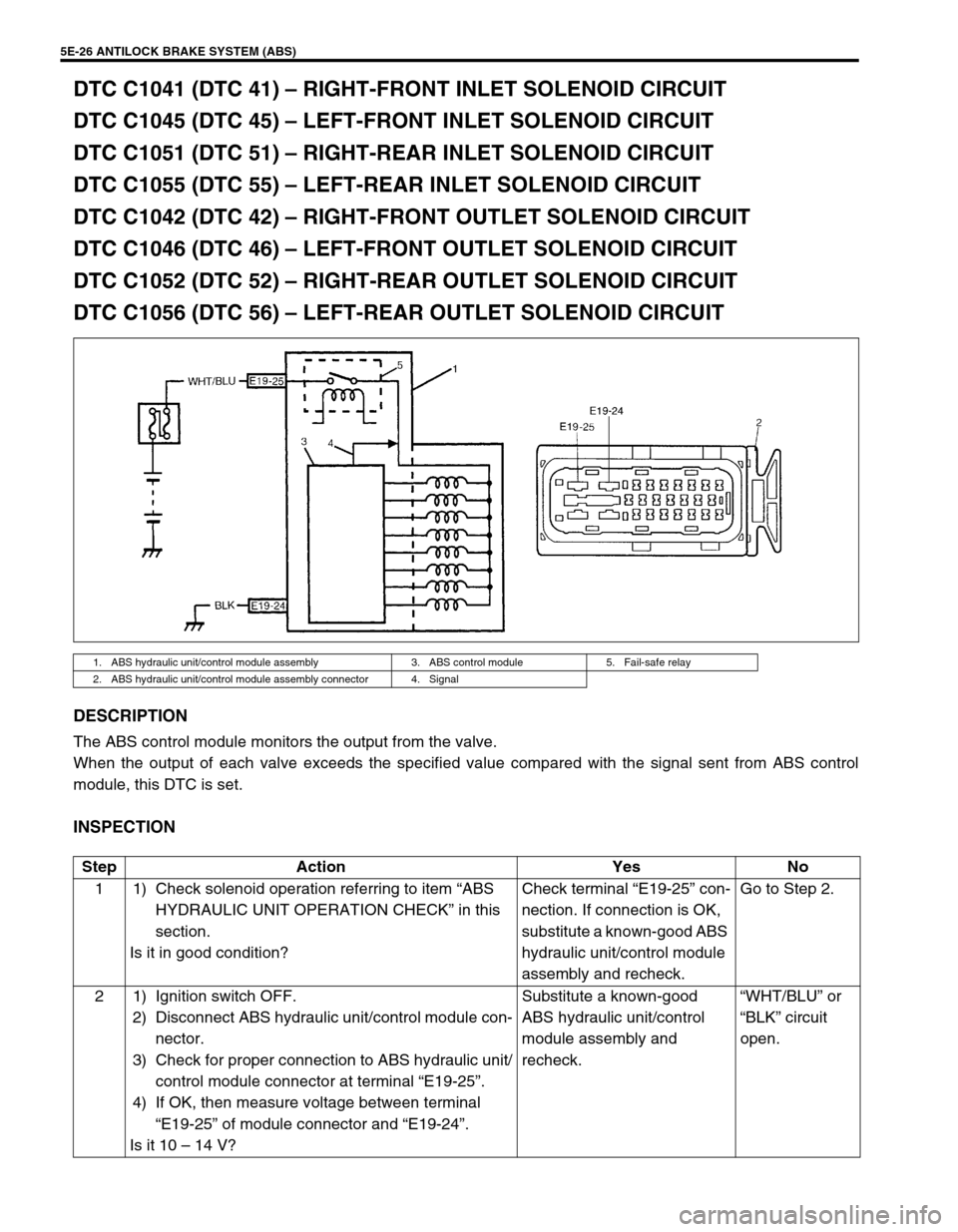
DESCRIPTION
The ABS control module monitors the output from the valve.
When the output of each valve exceeds the specified value compared with the signal sent from ABS control
module, this DTC is set.
INSPECTION
1. ABS hydraulic unit/control module assembly 3. ABS control module 5. Fail-safe relay
2. ABS hydraulic unit/control module assembly connector 4. Signal
Step Action Yes No
1 1) Check solenoid operation referring to item “ABS
HYDRAULIC UNIT OPERATION CHECK” in this
section.
Is it in good condition?Check terminal “E19-25” con-
nection. If connection is OK,
substitute a known-good ABS
hydraulic unit/control module
assembly and recheck.Go to Step 2.
2 1) Ignition switch OFF.
2) Disconnect ABS hydraulic unit/control module con-
nector.
3) Check for proper connection to ABS hydraulic unit/
control module connector at terminal “E19-25”.
4) If OK, then measure voltage between terminal
“E19-25” of module connector and “E19-24”.
Is it 10 – 14 V?Substitute a known-good
ABS hydraulic unit/control
module assembly and
recheck.“WHT/BLU” or
“BLK” circuit
open.
Page 363 of 698
5E-38 ANTILOCK BRAKE SYSTEM (ABS)
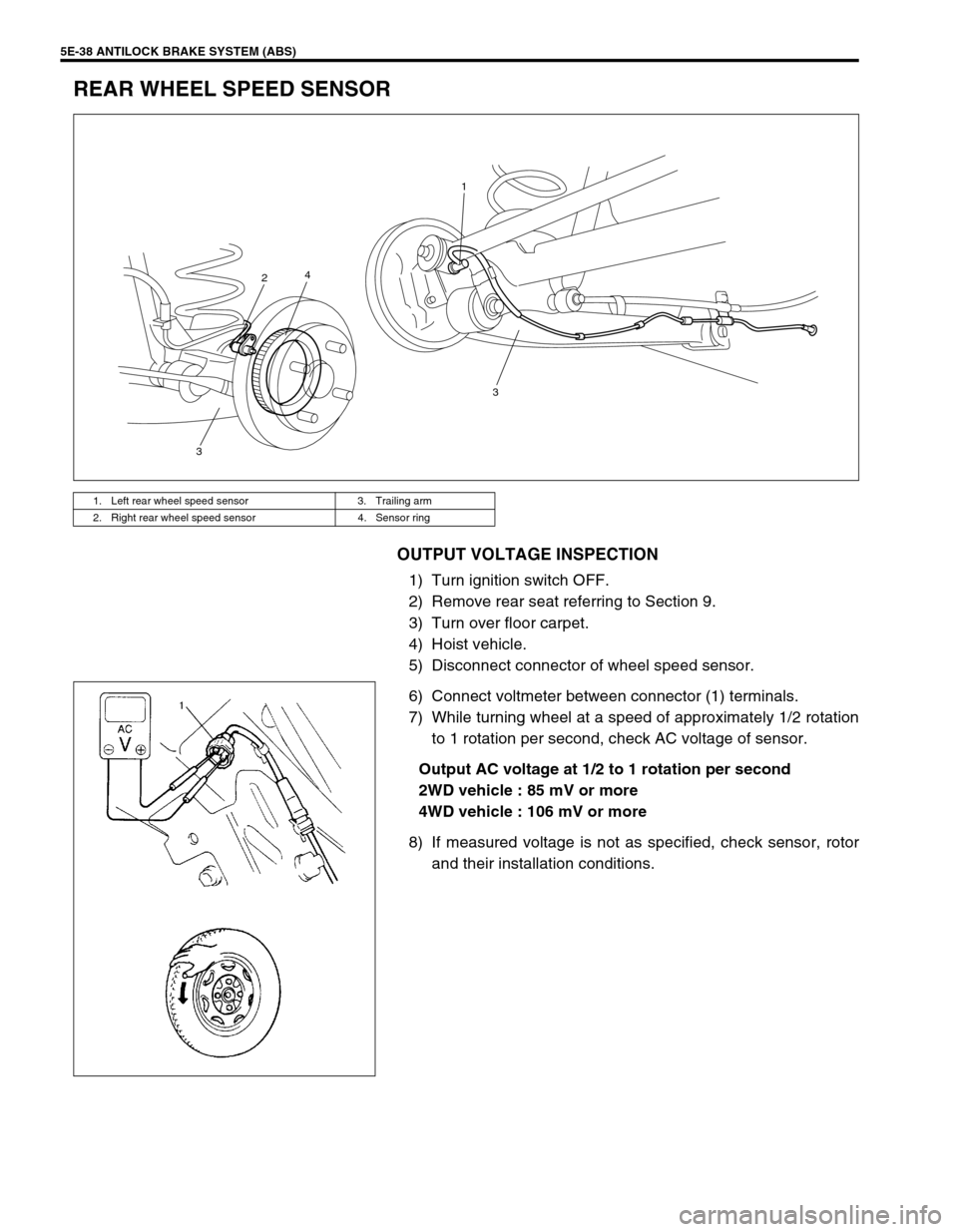
REAR WHEEL SPEED SENSOR
OUTPUT VOLTAGE INSPECTION
1) Turn ignition switch OFF.
2) Remove rear seat referring to Section 9.
3) Turn over floor carpet.
4) Hoist vehicle.
5) Disconnect connector of wheel speed sensor.
6) Connect voltmeter between connector (1) terminals.
7) While turning wheel at a speed of approximately 1/2 rotation
to 1 rotation per second, check AC voltage of sensor.
Output AC voltage at 1/2 to 1 rotation per second
2WD vehicle : 85 mV or more
4WD vehicle : 106 mV or more
8) If measured voltage is not as specified, check sensor, rotor
and their installation conditions.
1. Left rear wheel speed sensor 3. Trailing arm
2. Right rear wheel speed sensor 4. Sensor ring
3 1
4
2
3
Page 364 of 698
ANTILOCK BRAKE SYSTEM (ABS) 5E-39
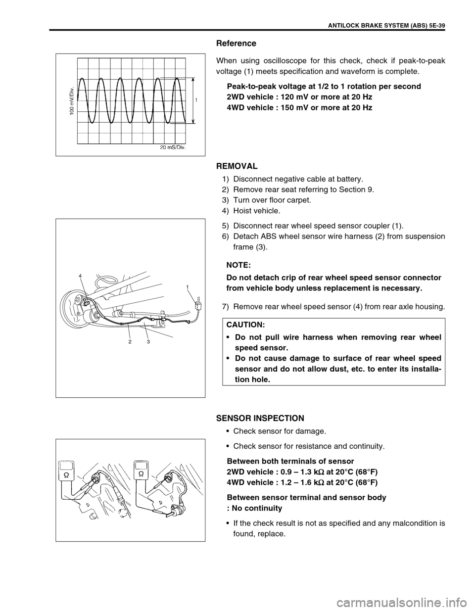
Reference
When using oscilloscope for this check, check if peak-to-peak
voltage (1) meets specification and waveform is complete.
Peak-to-peak voltage at 1/2 to 1 rotation per second
2WD vehicle : 120 mV or more at 20 Hz
4WD vehicle : 150 mV or more at 20 Hz
REMOVAL
1) Disconnect negative cable at battery.
2) Remove rear seat referring to Section 9.
3) Turn over floor carpet.
4) Hoist vehicle.
5) Disconnect rear wheel speed sensor coupler (1).
6) Detach ABS wheel sensor wire harness (2) from suspension
frame (3).
7) Remove rear wheel speed sensor (4) from rear axle housing.
SENSOR INSPECTION
Check sensor for damage.
Check sensor for resistance and continuity.
Between both terminals of sensor
2WD vehicle : 0.9 – 1.3 k
Ω
ΩΩ Ω at 20°C (68°F)
4WD vehicle : 1.2 – 1.6 k
Ω
ΩΩ Ω at 20°C (68°F)
Between sensor terminal and sensor body
: No continuity
If the check result is not as specified and any malcondition is
found, replace.
NOTE:
Do not detach crip of rear wheel speed sensor connector
from vehicle body unless replacement is necessary.
CAUTION:
Do not pull wire harness when removing rear wheel
speed sensor.
Do not cause damage to surface of rear wheel speed
sensor and do not allow dust, etc. to enter its installa-
tion hole.
4
231
Page 365 of 698
5E-40 ANTILOCK BRAKE SYSTEM (ABS)
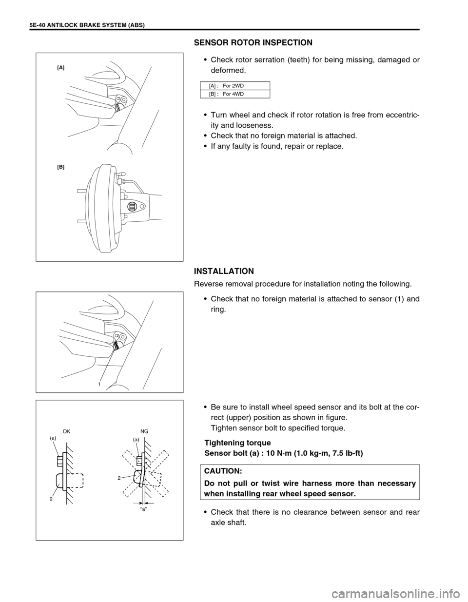
SENSOR ROTOR INSPECTION
Check rotor serration (teeth) for being missing, damaged or
deformed.
Turn wheel and check if rotor rotation is free from eccentric-
ity and looseness.
Check that no foreign material is attached.
If any faulty is found, repair or replace.
INSTALLATION
Reverse removal procedure for installation noting the following.
Check that no foreign material is attached to sensor (1) and
ring.
Be sure to install wheel speed sensor and its bolt at the cor-
rect (upper) position as shown in figure.
Tighten sensor bolt to specified torque.
Tightening torque
Sensor bolt (a) : 10 N·m (1.0 kg-m, 7.5 lb-ft)
Check that there is no clearance between sensor and rear
axle shaft.
[A] : For 2WD
[B] : For 4WD
[B] [A]
1
CAUTION:
Do not pull or twist wire harness more than necessary
when installing rear wheel speed sensor.
Page 366 of 698
ANTILOCK BRAKE SYSTEM (ABS) 5E-41
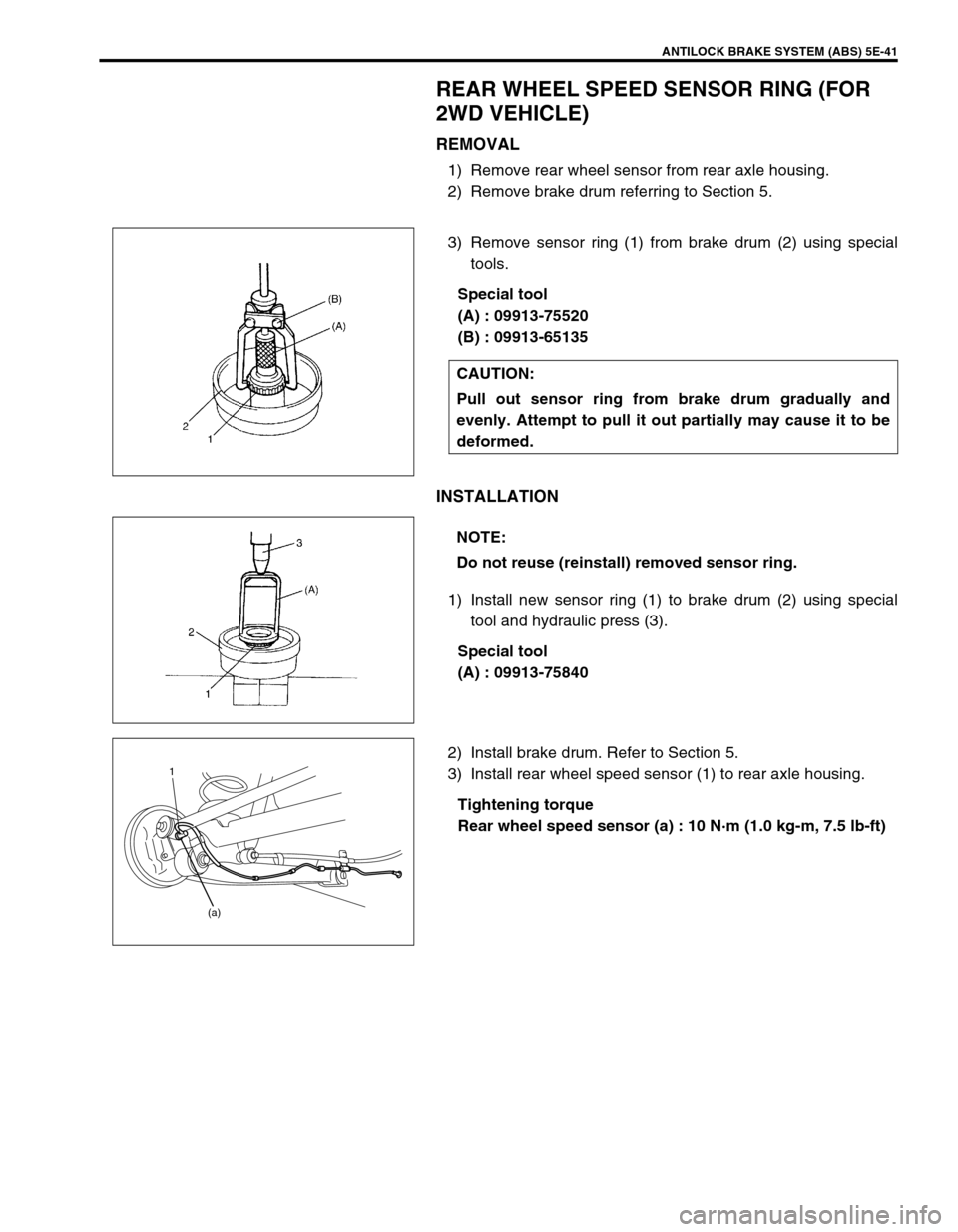
REAR WHEEL SPEED SENSOR RING (FOR
2WD VEHICLE)
REMOVAL
1) Remove rear wheel sensor from rear axle housing.
2) Remove brake drum referring to Section 5.
3) Remove sensor ring (1) from brake drum (2) using special
tools.
Special tool
(A) : 09913-75520
(B) : 09913-65135
INSTALLATION
1) Install new sensor ring (1) to brake drum (2) using special
tool and hydraulic press (3).
Special tool
(A) : 09913-75840
2) Install brake drum. Refer to Section 5.
3) Install rear wheel speed sensor (1) to rear axle housing.
Tightening torque
Rear wheel speed sensor (a) : 10 N·m (1.0 kg-m, 7.5 lb-ft) CAUTION:
Pull out sensor ring from brake drum gradually and
evenly. Attempt to pull it out partially may cause it to be
deformed.
NOTE:
Do not reuse (reinstall) removed sensor ring.
1
(a)
Page 367 of 698
5E-42 ANTILOCK BRAKE SYSTEM (ABS)
REAR WHEEL SPEED SENSOR RING (FOR
4WD VEHICLE)
REMOVAL
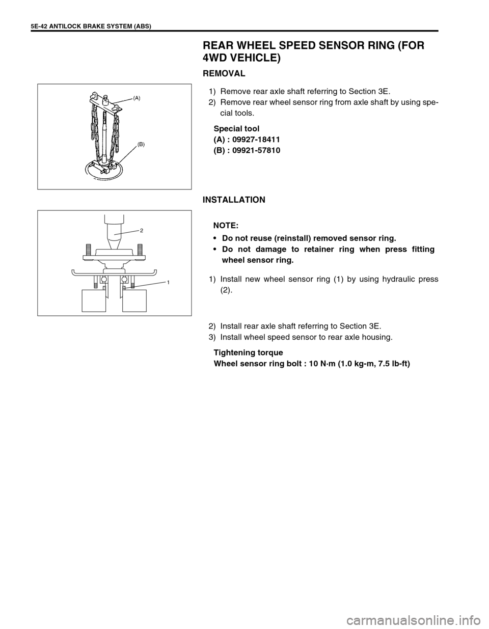
1) Remove rear axle shaft referring to Section 3E.
2) Remove rear wheel sensor ring from axle shaft by using spe-
cial tools.
Special tool
(A) : 09927-18411
(B) : 09921-57810
INSTALLATION
1) Install new wheel sensor ring (1) by using hydraulic press
(2).
2) Install rear axle shaft referring to Section 3E.
3) Install wheel speed sensor to rear axle housing.
Tightening torque
Wheel sensor ring bolt : 10 N·m (1.0 kg-m, 7.5 lb-ft)
NOTE:
Do not reuse (reinstall) removed sensor ring.
Do not damage to retainer ring when press fitting
wheel sensor ring.
1 2
Page 368 of 698
ANTILOCK BRAKE SYSTEM (ABS) 5E-43
G SENSOR (FOR 4WD VEHICLE ONLY)
REMOVAL
1) Turn ignition switch OFF and disconnect battery negative
cable.
2) Remove ABS fuse from fuse box.
3) Disconnect ABS hydraulic unit/control module assembly
connector by pulling up lock.
4) Remove center console box.
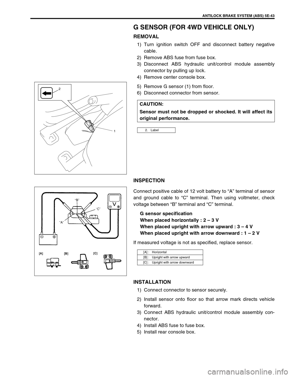
5) Remove G sensor (1) from floor.
6) Disconnect connector from sensor.
INSPECTION
Connect positive cable of 12 volt battery to “A” terminal of sensor
and ground cable to “C” terminal. Then using voltmeter, check
voltage between “B” terminal and “C” terminal.
G sensor specification
When placed horizontally : 2 – 3 V
When placed upright with arrow upward : 3 – 4 V
When placed upright with arrow downward : 1 – 2 V
If measured voltage is not as specified, replace sensor.
INSTALLATION
1) Connect connector to sensor securely.
2) Install sensor onto floor so that arrow mark directs vehicle
forward.
3) Connect ABS hydraulic unit/control module assembly con-
nector.
4) Install ABS fuse to fuse box.
5) Install rear console box.CAUTION:
Sensor must not be dropped or shocked. It will affect its
original performance.
2. Label1
2
[A] : Horizontal
[B] : Upright with arrow upward
[C] : Upright with arrow downward