light SUZUKI SWIFT 2000 1.G RG413 Service Repair Manual
[x] Cancel search | Manufacturer: SUZUKI, Model Year: 2000, Model line: SWIFT, Model: SUZUKI SWIFT 2000 1.GPages: 698, PDF Size: 16.01 MB
Page 491 of 698
![SUZUKI SWIFT 2000 1.G RG413 Service Repair Manual 6-122 ENGINE GENERAL INFORMATION AND DIAGNOSIS
TABLE B-4 IDLE AIR CONTROL SYSTEM CHECK
INSPECTION
1. IAC valve 2. Main relay 3. To TCM
[A] : Case of TYPE A is shown (See NOTE) [B] : Case of TYPE B is SUZUKI SWIFT 2000 1.G RG413 Service Repair Manual 6-122 ENGINE GENERAL INFORMATION AND DIAGNOSIS
TABLE B-4 IDLE AIR CONTROL SYSTEM CHECK
INSPECTION
1. IAC valve 2. Main relay 3. To TCM
[A] : Case of TYPE A is shown (See NOTE) [B] : Case of TYPE B is](/img/20/7606/w960_7606-490.png)
6-122 ENGINE GENERAL INFORMATION AND DIAGNOSIS
TABLE B-4 IDLE AIR CONTROL SYSTEM CHECK
INSPECTION
1. IAC valve 2. Main relay 3. To TCM
[A] : Case of TYPE A is shown (See NOTE) [B] : Case of TYPE B is shown (See NOTE)
GRN/RED
BLK/YEL
BRN/WHT
BLK/RED
BLK/RED
ECM
C41-10
C41-6
C41-5
C42 (31P) C41 (24P) G02 (17P)1 2 3 4 5 6 7 8 9
10 11 12 13 14 15 16 17 18 19 20 21
22 23 24 25 26 28 27 29 30 315 6
1 2 3 4 5 6 7
11 12
9 10 11 13 12 14 15 16
16 171 2
7 8
13 14 3 4
9 10
15 17 188
19 20 21 22 23 24
3
1
2
C42-6 C41-14 [A]
G02-6 [B]
LT BLU [A]
GRN RED [B]
NOTE:
For TYPE A and TYPE B, refer to NOTE in “ECM VOLTAGE VALUES TABLE” for applicable model.
Step Action Yes No
1 Check engine idle speed and IAC duty referring
to “Idle Speed/IAC Duty Inspection” in Section
6E1.
Is idle speed within specification?Go to Step 2. Go to Step 4.
2 Is IAC duty within specification in Step 1? Go to Step 3. Check for followings :
Vacuum leak
EVAP canister purge con-
trol system
Clog of IAC air passage
Accessory engine load
Closed throttle position
(TP sensor)
Stuck of PCV valve
3 Is engine idle speed kept specified speed even
with headlight ON?System is in good condi-
tion.Check IAC system for
operation referring to Step
2 of DTC P0505 Diag.
Flow Table.
4 Was idle speed higher than specification in
Step 1?Go to Step 5. Go to Step 8.
Page 496 of 698
![SUZUKI SWIFT 2000 1.G RG413 Service Repair Manual ENGINE GENERAL INFORMATION AND DIAGNOSIS 6-127
Fig. 1 for Step 2
Fig. 2 for Step 3
Table 1 for Step 2 and 3
[A] : When using SUZUKI scan tool:
[ A]
[A] : When not using SUZUKI scan tool:
[a] : Case of SUZUKI SWIFT 2000 1.G RG413 Service Repair Manual ENGINE GENERAL INFORMATION AND DIAGNOSIS 6-127
Fig. 1 for Step 2
Fig. 2 for Step 3
Table 1 for Step 2 and 3
[A] : When using SUZUKI scan tool:
[ A]
[A] : When not using SUZUKI scan tool:
[a] : Case of](/img/20/7606/w960_7606-495.png)
ENGINE GENERAL INFORMATION AND DIAGNOSIS 6-127
Fig. 1 for Step 2
Fig. 2 for Step 3
Table 1 for Step 2 and 3
[A] : When using SUZUKI scan tool:
[ A]
[A] : When not using SUZUKI scan tool:
[a] : Case of TYPE A is shown (See NOTE)
[b] : Case of TYPE B is shown (See NOTE)
Scan tool or voltmeter
SUZUKI
SCAN TOOLVOLTAGE
AT C42-17VOLTAGE
AT G02-13
Ignition switch ON, Small
light, heater blower fan and
rear defogger all turnedOFF OFF 0V 10 – 14V
ON ON 10 – 14V 0V
Page 506 of 698
ENGINE MECHANICAL (M13 ENGINE) 6A1-5
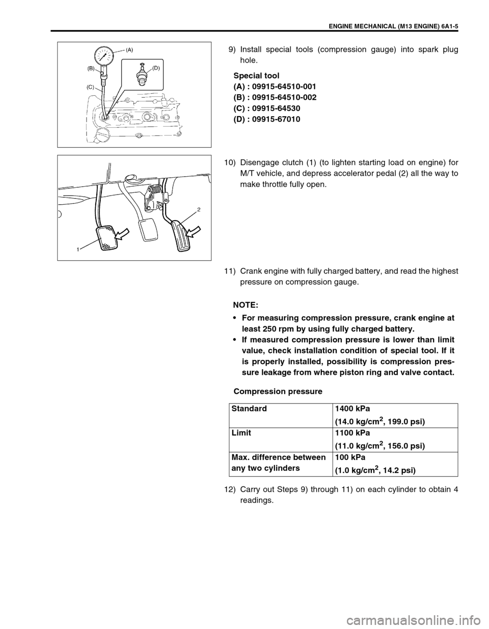
9) Install special tools (compression gauge) into spark plug
hole.
Special tool
(A) : 09915-64510-001
(B) : 09915-64510-002
(C) : 09915-64530
(D) : 09915-67010
10) Disengage clutch (1) (to lighten starting load on engine) for
M/T vehicle, and depress accelerator pedal (2) all the way to
make throttle fully open.
11) Crank engine with fully charged battery, and read the highest
pressure on compression gauge.
Compression pressure
12) Carry out Steps 9) through 11) on each cylinder to obtain 4
readings.
NOTE:
For measuring compression pressure, crank engine at
least 250 rpm by using fully charged battery.
If measured compression pressure is lower than limit
value, check installation condition of special tool. If it
is properly installed, possibility is compression pres-
sure leakage from where piston ring and valve contact.
Standard 1400 kPa
(14.0 kg/cm
2, 199.0 psi)
Limit 1100 kPa
(11.0 kg/cm
2, 156.0 psi)
Max. difference between
any two cylinders100 kPa
(1.0 kg/cm
2, 14.2 psi)
Page 570 of 698
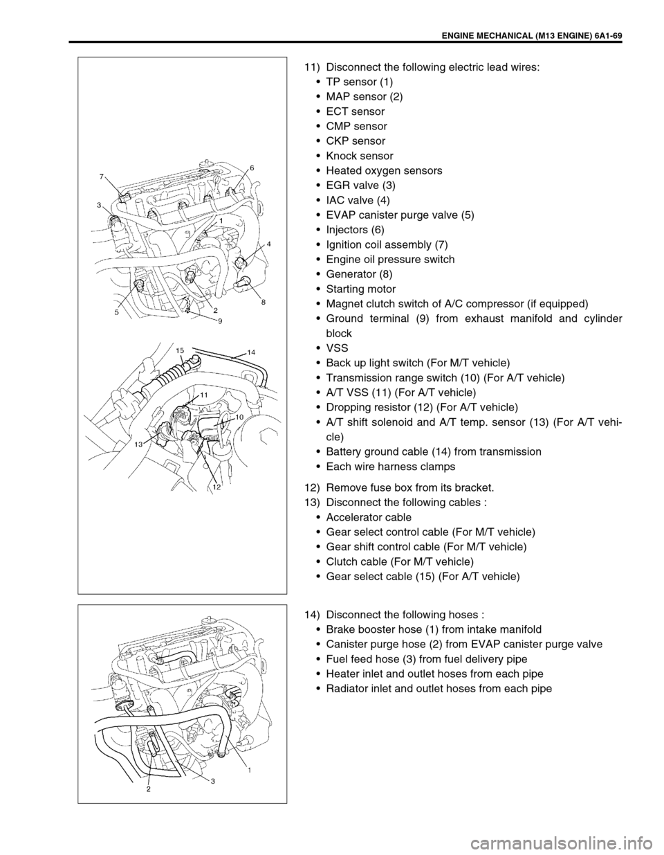
ENGINE MECHANICAL (M13 ENGINE) 6A1-69
11) Disconnect the following electric lead wires:
TP sensor (1)
MAP sensor (2)
ECT sensor
CMP sensor
CKP sensor
Knock sensor
Heated oxygen sensors
EGR valve (3)
IAC valve (4)
EVAP canister purge valve (5)
Injectors (6)
Ignition coil assembly (7)
Engine oil pressure switch
Generator (8)
Starting motor
Magnet clutch switch of A/C compressor (if equipped)
Ground terminal (9) from exhaust manifold and cylinder
block
VSS
Back up light switch (For M/T vehicle)
Transmission range switch (10) (For A/T vehicle)
A/T VSS (11) (For A/T vehicle)
Dropping resistor (12) (For A/T vehicle)
A/T shift solenoid and A/T temp. sensor (13) (For A/T vehi-
cle)
Battery ground cable (14) from transmission
Each wire harness clamps
12) Remove fuse box from its bracket.
13) Disconnect the following cables :
Accelerator cable
Gear select control cable (For M/T vehicle)
Gear shift control cable (For M/T vehicle)
Clutch cable (For M/T vehicle)
Gear select cable (15) (For A/T vehicle)
14) Disconnect the following hoses :
Brake booster hose (1) from intake manifold
Canister purge hose (2) from EVAP canister purge valve
Fuel feed hose (3) from fuel delivery pipe
Heater inlet and outlet hoses from each pipe
Radiator inlet and outlet hoses from each pipe
Page 629 of 698
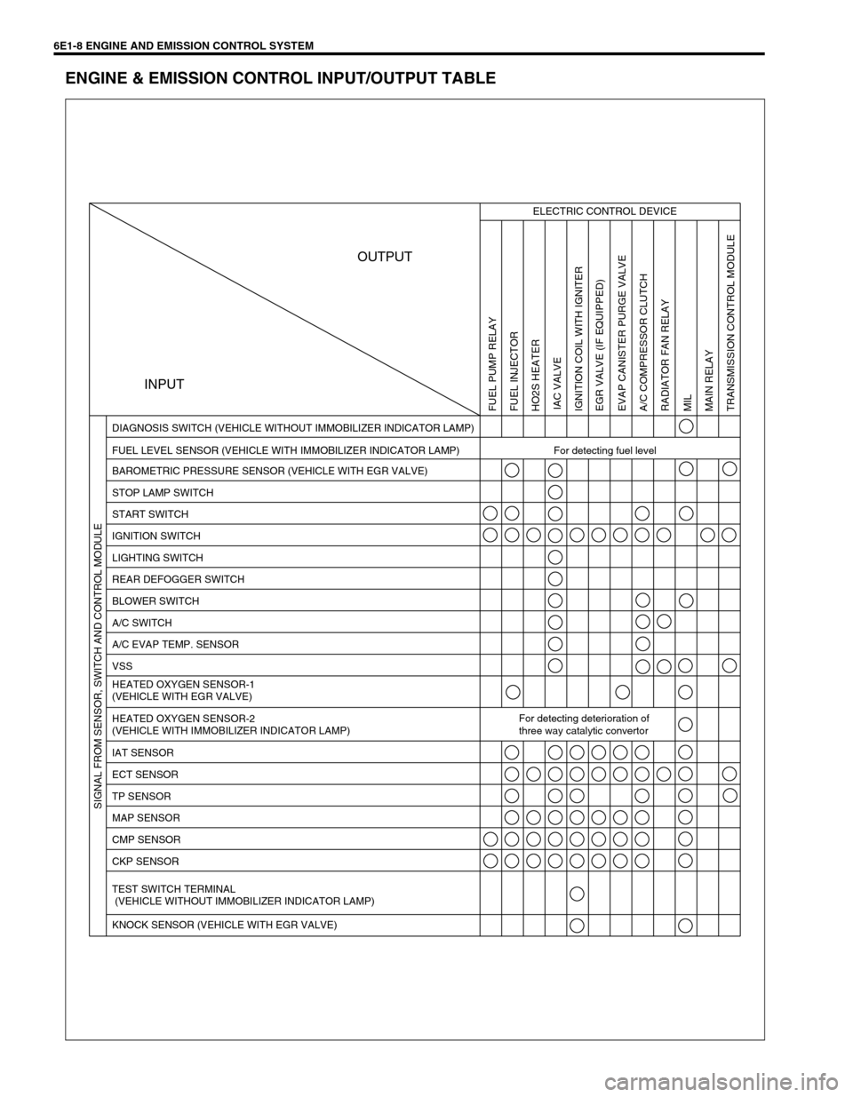
6E1-8 ENGINE AND EMISSION CONTROL SYSTEM
ENGINE & EMISSION CONTROL INPUT/OUTPUT TABLE
INPUTOUTPUT
ELECTRIC CONTROL DEVICE
FUEL LEVEL SENSOR (VEHICLE WITH IMMOBILIZER INDICATOR LAMP) For detecting fuel level DIAGNOSIS SWITCH (VEHICLE WITHOUT IMMOBILIZER INDICATOR LAMP)
BAROMETRIC PRESSURE SENSOR (VEHICLE WITH EGR VALVE)
STOP LAMP SWITCH
START SWITCH
IGNITION SWITCH
LIGHTING SWITCH
REAR DEFOGGER SWITCH
BLOWER SWITCH
A/C SWITCH
A/C EVAP TEMP. SENSOR
VSS
HEATED OXYGEN SENSOR-1
(VEHICLE WITH EGR VALVE)
HEATED OXYGEN SENSOR-2
(VEHICLE WITH IMMOBILIZER INDICATOR LAMP)For detecting deterioration of
three way catalytic convertor
IAT SENSOR
ECT SENSOR
TP SENSOR
MAP SENSOR
CMP SENSOR
CKP SENSOR
TEST SWITCH TERMINAL
(VEHICLE WITHOUT IMMOBILIZER INDICATOR LAMP)
KNOCK SENSOR (VEHICLE WITH EGR VALVE)
FUEL PUMP RELAY
FUEL INJECTOR
HO2S HEATER
IAC VALVE
IGNITION COIL WITH IGNITER
EGR VALVE (IF EQUIPPED)
EVAP CANISTER PURGE VALVE
A/C COMPRESSOR CLUTCH
RADIATOR FAN RELAY
MIL
MAIN RELAY
TRANSMISSION CONTROL MODULE SIGNAL FROM SENSOR, SWITCH AND CONTROL MODULE
Page 630 of 698
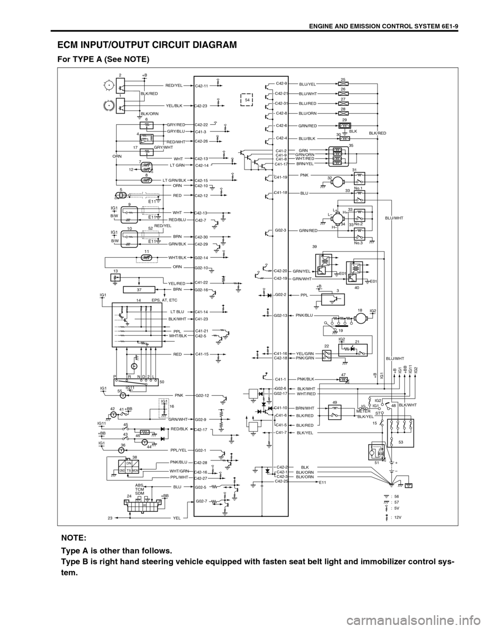
ENGINE AND EMISSION CONTROL SYSTEM 6E1-9
ECM INPUT/OUTPUT CIRCUIT DIAGRAM
For TYPE A (See NOTE)
37
C41-23
G02-12 IG1PNK 5554
BLK
C41-2
C41-9
C41-8
C41-17C42-13
17
2+B
1
6
8
5
IG1
IG1
14C42-9
C42-11
C42-23
C42-22
C41-3
C42-26
C42-14
C42-15
C42-10
C42-12
C42-13
C42-7
C42-30
C42-29
G02-14
G02-10
G02-16
C41-14
C41-21
C42-5
C41-15
G02-9
C42-17
G02-1
C42-28
C42-27 C42-16
G02-5C42-21
C42-31
C42-8
C42-6
C42-4
C41-19
C41-18
G02-3
G02-2
G02-13
C41-16
C42-18
C41-1
C41-10
C41-6
C41-5
C41-7
C42-1 C42-2
C42-3
C42-25G02-6
G02-173E01
E01 C42-20
C42-19L+
L–
H–H+ 25
26
27
28
29
30
35
31
No.1
No.2
No.3 32
33
33
33 34
IG2
IG2
+B
+B
IG1
+BB
IG11
IG2 IG1
21
47
49
IG
METERIG1
ST
15IG2
48
53
E11+
– 2218
PRND2L
IG11
IG11
+BB
IG145 41
ABS
TCM
SDM
24IG1
+BB50
16
E11
E1194
7
12
+BB
GND
: 56 : 57
IG1
E11 10
11
+B RED/YELBLU/YEL
BLU/WHT
BLU/RED
BLU/ORN
GRN/RED
BLU/BLK
PNK
BLU
GRN/RED
GRN/YEL39
40 GRN/WHT
PPL
YEL/GRN PNK/BLU
PNK/GRN
PNK/BLK
BLK/WHT
WHT/RED
BRN/WHT
BLK/RED
BLK/RED
BLK/YEL
BLK/ORNBLK
BLK/ORN YEL/BLK
GRY/RED
GRY/BLU
RED/WHT
GRY/WHT
LT GRN
LT GRN/BLK
ORN
RED
WHT
RED/BLU
BRN
GRN/BLK
WHT/BLK
ORN
BRN
EPS, AT, ETC
LT BLU
PPL
WHT/BLK
GRN/WHT
RED/BLK
PPL/YEL
PNK/BLU
WHT/GRN
BLU
B/W
B/W
BLK/WHT
RED
42
46 43
44 36
DN
TSGND MONPPL/WHT 38
G02-7
YEL
BLK/RED
GRN
GRN/ORN
BRN/YEL
51
2352
C41-22YEL/RED 13WHT
19
ORN
: 5V
: 12V
BLU/WHT
BLK/WHT
BLU/WHT
BLK/YEL
BLK/RED
BLK/ORN
WHT/RED
RED/YEL
NOTE:
Type A is other than follows.
Type B is right hand steering vehicle equipped with fasten seat belt light and immobilizer control sys-
tem.
Page 631 of 698
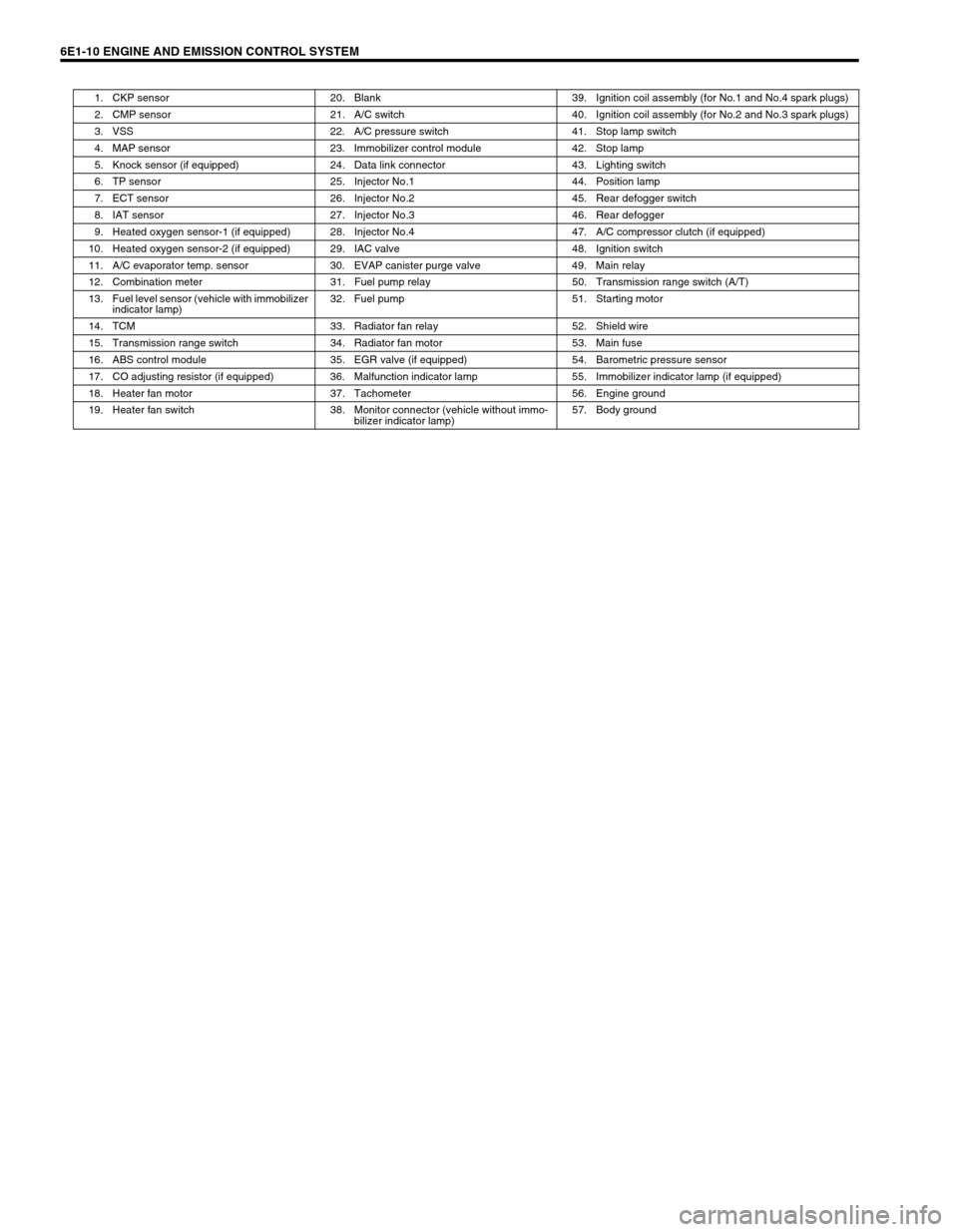
6E1-10 ENGINE AND EMISSION CONTROL SYSTEM
1. CKP sensor 20. Blank 39. Ignition coil assembly (for No.1 and No.4 spark plugs)
2. CMP sensor 21. A/C switch 40. Ignition coil assembly (for No.2 and No.3 spark plugs)
3. VSS 22. A/C pressure switch 41. Stop lamp switch
4. MAP sensor 23. Immobilizer control module 42. Stop lamp
5. Knock sensor (if equipped) 24. Data link connector 43. Lighting switch
6. TP sensor 25. Injector No.1 44. Position lamp
7. ECT sensor 26. Injector No.2 45. Rear defogger switch
8. IAT sensor 27. Injector No.3 46. Rear defogger
9. Heated oxygen sensor-1 (if equipped) 28. Injector No.4 47. A/C compressor clutch (if equipped)
10. Heated oxygen sensor-2 (if equipped) 29. IAC valve 48. Ignition switch
11. A/C evaporator temp. sensor 30. EVAP canister purge valve 49. Main relay
12. Combination meter 31. Fuel pump relay 50. Transmission range switch (A/T)
13. Fuel level sensor (vehicle with immobilizer
indicator lamp)32. Fuel pump 51. Starting motor
14. TCM 33. Radiator fan relay 52. Shield wire
15. Transmission range switch 34. Radiator fan motor 53. Main fuse
16. ABS control module 35. EGR valve (if equipped) 54. Barometric pressure sensor
17. CO adjusting resistor (if equipped) 36. Malfunction indicator lamp 55. Immobilizer indicator lamp (if equipped)
18. Heater fan motor 37. Tachometer 56. Engine ground
19. Heater fan switch 38. Monitor connector (vehicle without immo-
bilizer indicator lamp)57. Body ground
Page 633 of 698
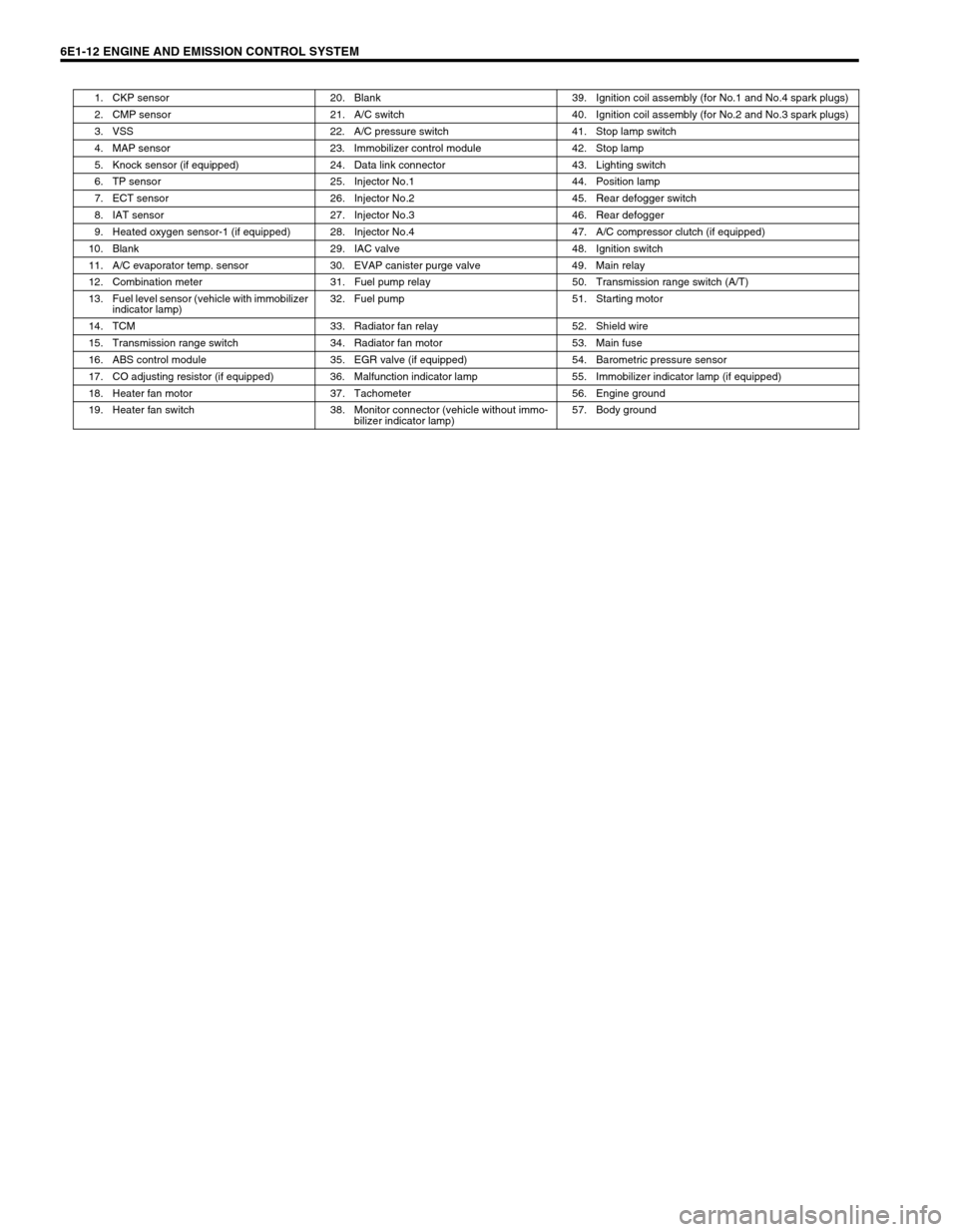
6E1-12 ENGINE AND EMISSION CONTROL SYSTEM
1. CKP sensor 20. Blank 39. Ignition coil assembly (for No.1 and No.4 spark plugs)
2. CMP sensor 21. A/C switch 40. Ignition coil assembly (for No.2 and No.3 spark plugs)
3. VSS 22. A/C pressure switch 41. Stop lamp switch
4. MAP sensor 23. Immobilizer control module 42. Stop lamp
5. Knock sensor (if equipped) 24. Data link connector 43. Lighting switch
6. TP sensor 25. Injector No.1 44. Position lamp
7. ECT sensor 26. Injector No.2 45. Rear defogger switch
8. IAT sensor 27. Injector No.3 46. Rear defogger
9. Heated oxygen sensor-1 (if equipped) 28. Injector No.4 47. A/C compressor clutch (if equipped)
10. Blank 29. IAC valve 48. Ignition switch
11. A/C evaporator temp. sensor 30. EVAP canister purge valve 49. Main relay
12. Combination meter 31. Fuel pump relay 50. Transmission range switch (A/T)
13. Fuel level sensor (vehicle with immobilizer
indicator lamp)32. Fuel pump 51. Starting motor
14. TCM 33. Radiator fan relay 52. Shield wire
15. Transmission range switch 34. Radiator fan motor 53. Main fuse
16. ABS control module 35. EGR valve (if equipped) 54. Barometric pressure sensor
17. CO adjusting resistor (if equipped) 36. Malfunction indicator lamp 55. Immobilizer indicator lamp (if equipped)
18. Heater fan motor 37. Tachometer 56. Engine ground
19. Heater fan switch 38. Monitor connector (vehicle without immo-
bilizer indicator lamp)57. Body ground
Page 636 of 698
ENGINE AND EMISSION CONTROL SYSTEM 6E1-15
ON-VEHICLE SERVICE
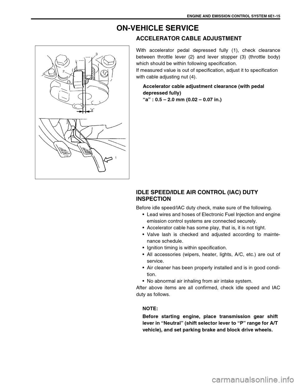
ACCELERATOR CABLE ADJUSTMENT
With accelerator pedal depressed fully (1), check clearance
between throttle lever (2) and lever stopper (3) (throttle body)
which should be within following specification.
If measured value is out of specification, adjust it to specification
with cable adjusting nut (4).
Accelerator cable adjustment clearance (with pedal
depressed fully)
“a” : 0.5 – 2.0 mm (0.02 – 0.07 in.)
IDLE SPEED/IDLE AIR CONTROL (IAC) DUTY
INSPECTION
Before idle speed/IAC duty check, make sure of the following.
Lead wires and hoses of Electronic Fuel Injection and engine
emission control systems are connected securely.
Accelerator cable has some play, that is, it is not tight.
Valve lash is checked and adjusted according to mainte-
nance schedule.
Ignition timing is within specification.
All accessories (wipers, heater, lights, A/C, etc.) are out of
service.
Air cleaner has been properly installed and is in good condi-
tion.
No abnormal air inhaling from air intake system.
After above items are all confirmed, check idle speed and IAC
duty as follows.
NOTE:
Before starting engine, place transmission gear shift
lever in “Neutral” (shift selector lever to “P” range for A/T
vehicle), and set parking brake and block drive wheels.
Page 670 of 698

6F1-8 IGNITION SYSTEM (ELECTRONIC IGNITION SYSTEM)
IGNITION TIMING
INSPECTION
1) When using SUZUKI scan tool, connect SUZUKI scan tool to
DLC with ignition switch OFF.
Special tool
(A) : 09931-76011 (SUZUKI scan tool)
(B) : Mass storage cartridge
(C) : 09931-76030 (16/14 pin DLC cable)
2) Start engine and warm it up to normal operating tempera-
ture.
3) Make sure that all of electrical loads except ignition are
switched off.
4) Check to be sure that idle speed is within specification.
(Refer to Section 6E1)
5) Fix ignition timing to initial one as follows.
Select “MISC” mode on SUZUKI scan tool and fix ignition
timing to initial one.
If scan tool is not available (vehicle without immobilizer indi-
cator lamp), connect D and E terminals of monitor connector
(1) by using service wire so that ignition timing is fixed on ini-
tial one.
6) Using timing light (1), check that ignition timing is within
specification.
Initial ignition timing (test switch terminal grounded or
fixed with SUZUKI scan tool)
: 5
± 3° BTDC at idle speed
Ignition order
: 1-3-4-2 NOTE:
Ignition timing is not adjustable. If ignition timing is
out of specification, check system related parts.
Before starting engine, place transmission gear shift
lever in “Neutral” (shift selector lever to “P” range for
A/T model), and set parking brake.
(C)
(A)
(B)
D
E1