transmission SUZUKI SWIFT 2000 1.G Transmission Service Workshop Manual
[x] Cancel search | Manufacturer: SUZUKI, Model Year: 2000, Model line: SWIFT, Model: SUZUKI SWIFT 2000 1.GPages: 447, PDF Size: 10.54 MB
Page 181 of 447

AUTOMATIC TRANSMISSION (4 A/T) 7B-139
REQUIRED SERVICE MATERIAL
NOTE:
This kit includes the following items.
1. Storage case, 2. Operator’s manual, 3. SUZUKI scan tool (Tech-1A), 4. DLC cable,
5. Test lead / probe, 6. Power source cable, 7. DLC cable adaptor, 8. Self-test adaptor
MaterialRecommended SUZUKI product
(Part Number)Use
Automatic transmission fluid
An equivalent of DEXRON
®-III or
DEXRONR
®-IIEAutomatic transmission
Parts lubrication when installing
Sealant SUZUKI BOND No. 1215
(99000-31110)Case housing star-shaped recess
bolts
(3 pcs only)
Lithium grease SUZUKI SUPER GREASE C
(99000-25030)Retaining parts in place when
assembling
Oil seal lips
D-rings
O-rings
SUZUKI SUPER GREASE A
(99000-25010)Cable ends
Converter center cup
Thread lock cement THREAD LOCK 1322
(99000-32110)Final gear bolts
Torque converter housing bolts
Page 182 of 447

7B-140 AUTOMATIC TRANSMISSION (4 A/T)
Page 184 of 447
7C-2 CLUTCH
GENERAL DESCRIPTION
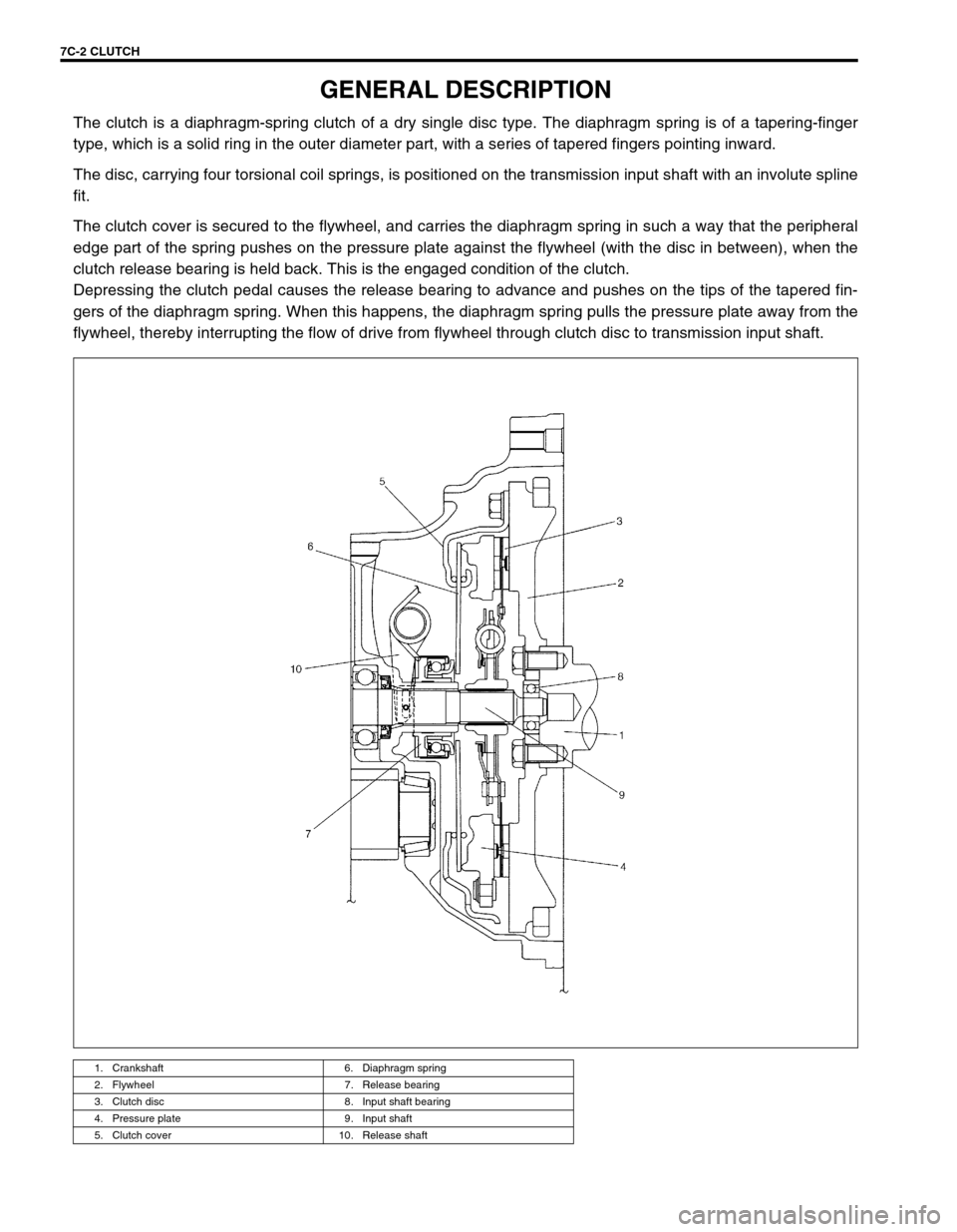
The clutch is a diaphragm-spring clutch of a dry single disc type. The diaphragm spring is of a tapering-finger
type, which is a solid ring in the outer diameter part, with a series of tapered fingers pointing inward.
The disc, carrying four torsional coil springs, is positioned on the transmission input shaft with an involute spline
fit.
The clutch cover is secured to the flywheel, and carries the diaphragm spring in such a way that the peripheral
edge part of the spring pushes on the pressure plate against the flywheel (with the disc in between), when the
clutch release bearing is held back. This is the engaged condition of the clutch.
Depressing the clutch pedal causes the release bearing to advance and pushes on the tips of the tapered fin-
gers of the diaphragm spring. When this happens, the diaphragm spring pulls the pressure plate away from the
flywheel, thereby interrupting the flow of drive from flywheel through clutch disc to transmission input shaft.
1. Crankshaft 6. Diaphragm spring
2. Flywheel 7. Release bearing
3. Clutch disc 8. Input shaft bearing
4. Pressure plate 9. Input shaft
5. Clutch cover 10. Release shaft
Page 185 of 447
CLUTCH 7C-3
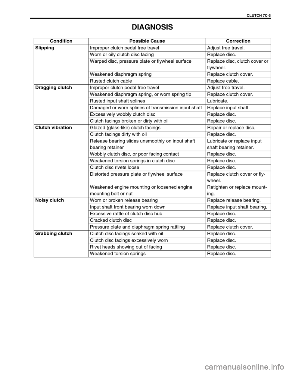
DIAGNOSIS
Condition Possible Cause Correction
Slipping
Improper clutch pedal free travel Adjust free travel.
Worn or oily clutch disc facing Replace disc.
Warped disc, pressure plate or flywheel surface Replace disc, clutch cover or
flywheel.
Weakened diaphragm spring Replace clutch cover.
Rusted clutch cable Replace cable.
Dragging clutch
Improper clutch pedal free travel Adjust free travel.
Weakened diaphragm spring, or worn spring tip Replace clutch cover.
Rusted input shaft splines Lubricate.
Damaged or worn splines of transmission input shaft Replace input shaft.
Excessively wobbly clutch disc Replace disc.
Clutch facings broken or dirty with oil Replace disc.
Clutch vibration
Glazed (glass-like) clutch facings Repair or replace disc.
Clutch facings dirty with oil Replace disc.
Release bearing slides unsmoothly on input shaft
bearing retainerLubricate or replace input
shaft bearing retainer.
Wobbly clutch disc, or poor facing contact Replace disc.
Weakened torsion springs in clutch disc Replace disc.
Clutch disc rivets loose Replace disc.
Distorted pressure plate or flywheel surface Replace clutch cover or fly-
wheel.
Weakened engine mounting or loosened engine
mounting bolt or nutRetighten or replace mount-
ing.
Noisy clutch
Worn or broken release bearing Replace release bearing.
Input shaft front bearing worn down Replace input shaft bearing.
Excessive rattle of clutch disc hub Replace disc.
Cracked clutch disc Replace disc.
Pressure plate and diaphragm spring rattling Replace clutch cover.
Grabbing clutch
Clutch disc facings soaked with oil Replace disc.
Clutch disc facings excessively worn Replace disc.
Rivet heads showing out of facing Replace disc.
Weakened torsion springs Replace disc.
Page 190 of 447
7C-8 CLUTCH
UNIT REPAIR OVERHAUL
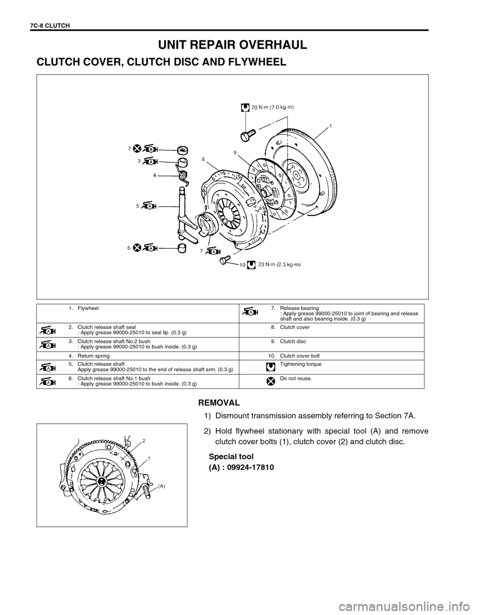
CLUTCH COVER, CLUTCH DISC AND FLYWHEEL
REMOVAL
1) Dismount transmission assembly referring to Section 7A.
2) Hold flywheel stationary with special tool (A) and remove
clutch cover bolts (1), clutch cover (2) and clutch disc.
Special tool
(A) : 09924-17810
1. Flywheel7. Release bearing
: Apply grease 99000-25010 to joint of bearing and release
shaft and also bearing inside. (0.3 g)
2. Clutch release shaft seal
: Apply grease 99000-25010 to seal lip. (0.3 g)8. Clutch cover
3. Clutch release shaft No.2 bush
: Apply grease 99000-25010 to bush inside. (0.3 g)9. Clutch disc
4. Return spring 10. Clutch cover bolt
5. Clutch release shaft
Apply grease 99000-25010 to the end of release shaft arm. (0.3 g)Tightening torque
6. Clutch release shaft No.1 bush
: Apply grease 99000-25010 to bush inside. (0.3 g)Do not reuse.
Page 193 of 447
CLUTCH 7C-11
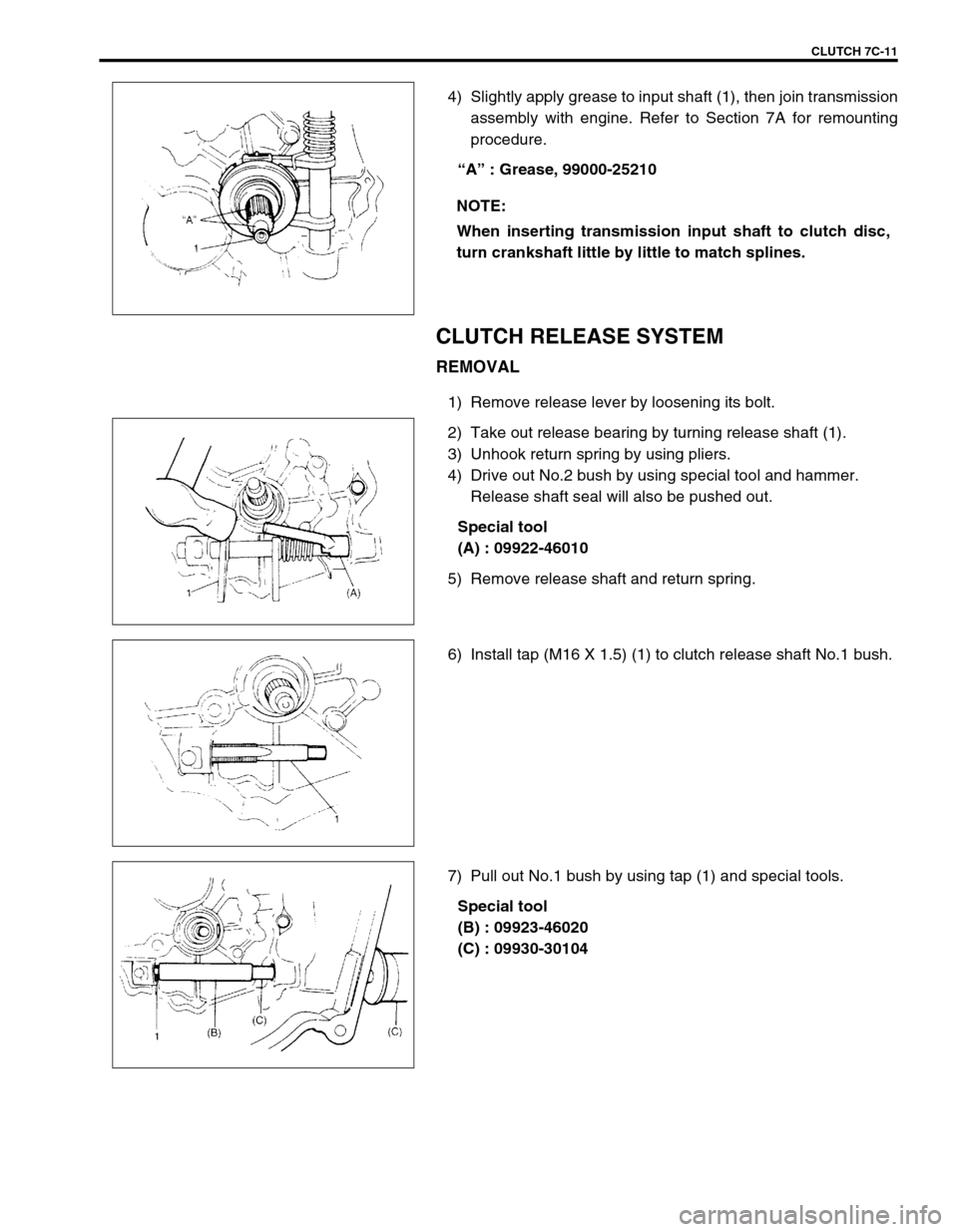
4) Slightly apply grease to input shaft (1), then join transmission
assembly with engine. Refer to Section 7A for remounting
procedure.
“A” : Grease, 99000-25210
CLUTCH RELEASE SYSTEM
REMOVAL
1) Remove release lever by loosening its bolt.
2) Take out release bearing by turning release shaft (1).
3) Unhook return spring by using pliers.
4) Drive out No.2 bush by using special tool and hammer.
Release shaft seal will also be pushed out.
Special tool
(A) : 09922-46010
5) Remove release shaft and return spring.
6) Install tap (M16 X 1.5) (1) to clutch release shaft No.1 bush.
7) Pull out No.1 bush by using tap (1) and special tools.
Special tool
(B) : 09923-46020
(C) : 09930-30104 NOTE:
When inserting transmission input shaft to clutch disc,
turn crankshaft little by little to match splines.
Page 203 of 447
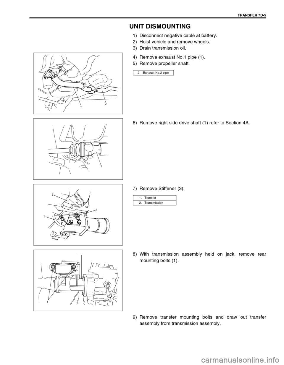
TRANSFER 7D-5
UNIT DISMOUNTING
1) Disconnect negative cable at battery.
2) Hoist vehicle and remove wheels.
3) Drain transmission oil.
4) Remove exhaust No.1 pipe (1).
5) Remove propeller shaft.
6) Remove right side drive shaft (1) refer to Section 4A.
7) Remove Stiffener (3).
8) With transmission assembly held on jack, remove rear
mounting bolts (1).
9) Remove transfer mounting bolts and draw out transfer
assembly from transmission assembly.
2. Exhaust No.2 pipe
12
1
1. Transfer
2. Transmission
1
Page 218 of 447

7D-20 TRANSFER
UNIT INSTALLATION
Install transfer assembly (2) by reversing removal procedure and
noting following points.
Tighten transfer mounting bolts (3) to specified torque.
Tightening torque
Transfer mounting bolts (a) : 50 N·m (5.0 kg-m, 36.5 lb-ft)
Tighten rear mounting bracket bolts (1) to specified torque.
Tightening torque
Transfer rear mounting bracket bolts
(a) : 55 N·m (5.5 kg-m, 40.0 lb-ft)These contact patterns indicate that the “offset” of
reduction driven gear is too much or too little. The rem-
edy is to change the division of the bevel gear shim(s).
These contact patterns, located on toe or heel on both
drive and coast sides, mean that 1) both pinion and
gear are defective, 2) retainer is not true, or 3) gear is
not properly seated on transfer case. The remedy is to
replace the defective member.
Irregular patterns: If the pattern is not oval, it means
that bevel gear is defective. High or low spots on tooth
surfaces or on the seat of bevel gear are the cause of
irregular patterns appearing on some teeth. The rem-
edy is to replace the pinion and gear set and, if the seat
is defective, so is transfer case. TOOTH CONTACT PATTERN DIAGNOSIS AND REMEDY
1. Transmission
1, (a)
Page 219 of 447

TRANSFER 7D-21
Tighten mounting bolt and mounting bracket bolts and nuts
to specified torque.
Tightening torque
Transfer rear mounting bracket nuts
(a) : 50 N·m (5.0 kg-m, 36.5 lb-ft)
Transfer mounting bolt
(b) : 55 N·m (5.5 kg-m, 40.0 lb-ft)
Transfer rear mounting bracket No.2 bolts
(c) : 55 N·m (5.5 kg-m, 40.0 lb-ft)
Tighten transfer stiffener bolts (4) to specified torque.
Tightening torque
Transfer stiffener bolts (a) : 50 N·m (5.0 kg-m, 36.5 lb-ft)
Tighten exhaust pipe bolts.
Tightening torque
Exhaust pipe bolts
(a) : 50 N·m (5.0 kg-m, 36.5 lb-ft)
Install right side drive shaft, refer to Section 4A.
Install propeller shaft and tighten propeller shaft bolts and
center support bolts to specified torque (refer to Section 4B).
Fill gear oil to transfer as specified, refer to OIL CHANGE of
ON-VEHICLE SERVICE.
Check oil level and leakage.
(a)
(b)
(c)
1. Transmission
2. Transfer
3. Stiffener
1. Exhaust No.1 pipe
2. Exhaust No.2 pipe
1
(a)(a)2