Air SUZUKI SWIFT 2000 1.G Transmission Service User Guide
[x] Cancel search | Manufacturer: SUZUKI, Model Year: 2000, Model line: SWIFT, Model: SUZUKI SWIFT 2000 1.GPages: 447, PDF Size: 10.54 MB
Page 57 of 447

AUTOMATIC TRANSMISSION (4 A/T) 7B-15
1. CUSTOMER COMPLAINT ANALYSIS
Record details of the problem (failure, complaint) and how it occurred as described by the customer. For this
purpose, use of such a questionnaire form as shown below will facilitate collecting information to the point
required for proper analysis and diagnosis.
CUSTOMER QUESTIONNAIRE (EXAMPLE)
NOTE:
The above form is a standard sample. It should be modified according to conditions
characteristic of each market.
Page 59 of 447
AUTOMATIC TRANSMISSION (4 A/T) 7B-17
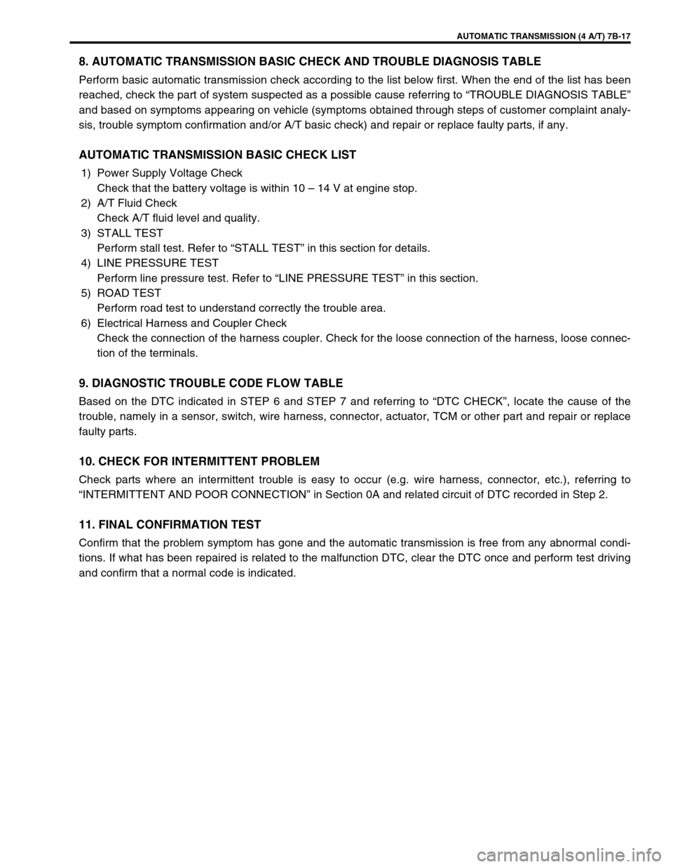
8. AUTOMATIC TRANSMISSION BASIC CHECK AND TROUBLE DIAGNOSIS TABLE
Perform basic automatic transmission check according to the list below first. When the end of the list has been
reached, check the part of system suspected as a possible cause referring to “TROUBLE DIAGNOSIS TABLE”
and based on symptoms appearing on vehicle (symptoms obtained through steps of customer complaint analy-
sis, trouble symptom confirmation and/or A/T basic check) and repair or replace faulty parts, if any.
AUTOMATIC TRANSMISSION BASIC CHECK LIST
1) Power Supply Voltage Check
Check that the battery voltage is within 10 – 14 V at engine stop.
2) A/T Fluid Check
Check A/T fluid level and quality.
3) STALL TEST
Perform stall test. Refer to “STALL TEST” in this section for details.
4) LINE PRESSURE TEST
Perform line pressure test. Refer to “LINE PRESSURE TEST” in this section.
5) ROAD TEST
Perform road test to understand correctly the trouble area.
6) Electrical Harness and Coupler Check
Check the connection of the harness coupler. Check for the loose connection of the harness, loose connec-
tion of the terminals.
9. DIAGNOSTIC TROUBLE CODE FLOW TABLE
Based on the DTC indicated in STEP 6 and STEP 7 and referring to “DTC CHECK”, locate the cause of the
trouble, namely in a sensor, switch, wire harness, connector, actuator, TCM or other part and repair or replace
faulty parts.
10. CHECK FOR INTERMITTENT PROBLEM
Check parts where an intermittent trouble is easy to occur (e.g. wire harness, connector, etc.), referring to
“INTERMITTENT AND POOR CONNECTION” in Section 0A and related circuit of DTC recorded in Step 2.
11. FINAL CONFIRMATION TEST
Confirm that the problem symptom has gone and the automatic transmission is free from any abnormal condi-
tions. If what has been repaired is related to the malfunction DTC, clear the DTC once and perform test driving
and confirm that a normal code is indicated.
Page 60 of 447
7B-18 AUTOMATIC TRANSMISSION (4 A/T)
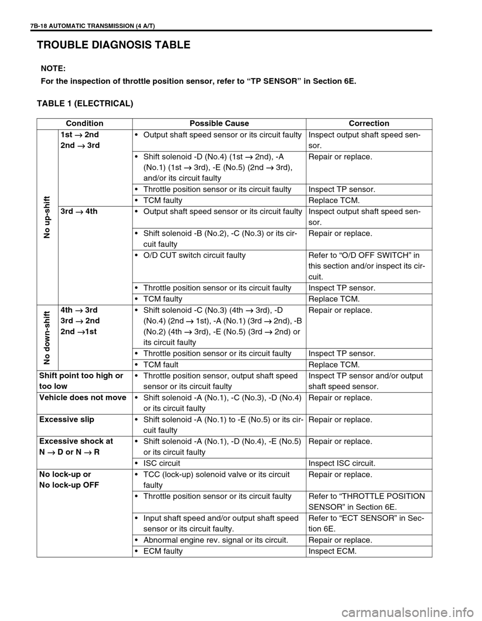
TROUBLE DIAGNOSIS TABLE
TABLE 1 (ELECTRICAL)
NOTE:
For the inspection of throttle position sensor, refer to “TP SENSOR” in Section 6E.
Condition Possible Cause Correction
No up-shift
1st
→
→→ → 2nd
2nd
→
→→ → 3rdOutput shaft speed sensor or its circuit faulty Inspect output shaft speed sen-
sor.
Shift solenoid -D (No.4) (1st →
→→ →
2nd), -A
(No.1) (1st →
→→ →
3rd), -E (No.5) (2nd →
→→ →
3rd),
and/or its circuit faultyRepair or replace.
Throttle position sensor or its circuit faulty Inspect TP sensor.
TCM faulty Replace TCM.
3rd
→
→→ → 4th
Output shaft speed sensor or its circuit faulty Inspect output shaft speed sen-
sor.
Shift solenoid -B (No.2), -C (No.3) or its cir-
cuit faultyRepair or replace.
O/D CUT switch circuit faulty Refer to “O/D OFF SWITCH” in
this section and/or inspect its cir-
cuit.
Throttle position sensor or its circuit faulty Inspect TP sensor.
TCM faulty Replace TCM.
No down-shift
4th
→
→→ → 3rd
3rd
→
→→ → 2nd
2nd
→
→→ →1stShift solenoid -C (No.3) (4th →
→→ →
3rd), -D
(No.4) (2nd →
→→ →
1st), -A (No.1) (3rd →
→→ →
2nd), -B
(No.2) (4th →
→→ →
3rd), -E (No.5) (3rd →
→→ →
2nd) or
its circuit faultyRepair or replace.
Throttle position sensor or its circuit faulty Inspect TP sensor.
TCM fault Replace TCM.
Shift point too high or
too lowThrottle position sensor, output shaft speed
sensor or its circuit faultyInspect TP sensor and/or output
shaft speed sensor.
Vehicle does not move
Shift solenoid -A (No.1), -C (No.3), -D (No.4)
or its circuit faultyRepair or replace.
Excessive slip
Shift solenoid -A (No.1) to -E (No.5) or its cir-
cuit faultyRepair or replace.
Excessive shock at
N
→
→→ → D or N
→
→→ → RShift solenoid -A (No.1), -D (No.4), -E (No.5)
or its circuit faultyRepair or replace.
ISC circuit Inspect ISC circuit.
No lock-up or
No lock-up OFFTCC (lock-up) solenoid valve or its circuit
faultyRepair or replace.
Throttle position sensor or its circuit faulty Refer to “THROTTLE POSITION
SENSOR” in Section 6E.
Input shaft speed and/or output shaft speed
sensor or its circuit faulty.Refer to “ECT SENSOR” in Sec-
tion 6E.
Abnormal engine rev. signal or its circuit. Repair or replace.
ECM faulty Inspect ECM.
Page 61 of 447
AUTOMATIC TRANSMISSION (4 A/T) 7B-19
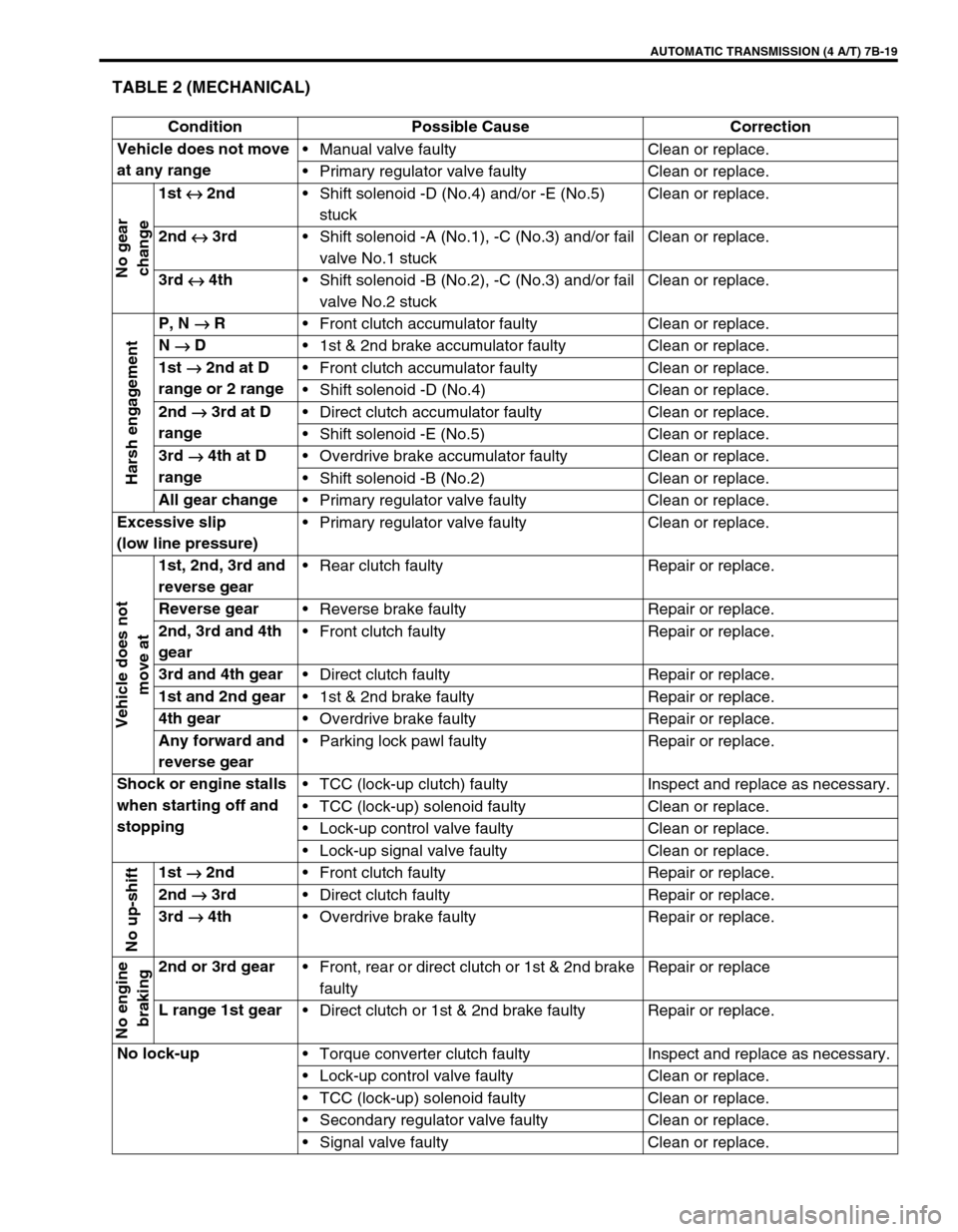
TABLE 2 (MECHANICAL)
Condition Possible Cause Correction
Vehicle does not move
at any rangeManual valve faulty Clean or replace.
Primary regulator valve faulty Clean or replace.
No gear
change
1st
↔
↔↔ ↔ 2nd
Shift solenoid -D (No.4) and/or -E (No.5)
stuck Clean or replace.
2nd
↔
↔↔ ↔ 3rd
Shift solenoid -A (No.1), -C (No.3) and/or fail
valve No.1 stuckClean or replace.
3rd
↔
↔↔ ↔ 4th
Shift solenoid -B (No.2), -C (No.3) and/or fail
valve No.2 stuckClean or replace.
Harsh engagement
P, N
→
→→ → R
Front clutch accumulator faulty Clean or replace.
N
→
→→ → D
1st & 2nd brake accumulator faulty Clean or replace.
1st
→
→→ → 2nd at D
range or 2 rangeFront clutch accumulator faulty Clean or replace.
Shift solenoid -D (No.4) Clean or replace.
2nd
→
→→ → 3rd at D
rangeDirect clutch accumulator faulty Clean or replace.
Shift solenoid -E (No.5) Clean or replace.
3rd
→
→→ → 4th at D
rangeOverdrive brake accumulator faulty Clean or replace.
Shift solenoid -B (No.2) Clean or replace.
All gear change
Primary regulator valve faulty Clean or replace.
Excessive slip
(low line pressure)Primary regulator valve faulty Clean or replace.
Vehicle does not
move at
1st, 2nd, 3rd and
reverse gearRear clutch faulty Repair or replace.
Reverse gear
Reverse brake faulty Repair or replace.
2nd, 3rd and 4th
gearFront clutch faulty Repair or replace.
3rd and 4th gear
Direct clutch faulty Repair or replace.
1st and 2nd gear
1st & 2nd brake faulty Repair or replace.
4th gear
Overdrive brake faulty Repair or replace.
Any forward and
reverse gearParking lock pawl faulty Repair or replace.
Shock or engine stalls
when starting off and
stoppingTCC (lock-up clutch) faulty Inspect and replace as necessary.
TCC (lock-up) solenoid faulty Clean or replace.
Lock-up control valve faulty Clean or replace.
Lock-up signal valve faulty Clean or replace.
No up-shift
1st
→
→→ → 2nd
Front clutch faulty Repair or replace.
2nd
→
→→ → 3rd
Direct clutch faulty Repair or replace.
3rd
→
→→ → 4th
Overdrive brake faulty Repair or replace.
No engine
braking
2nd or 3rd gear
Front, rear or direct clutch or 1st & 2nd brake
faultyRepair or replace
L range 1st gear
Direct clutch or 1st & 2nd brake faulty Repair or replace.
No lock-up
Torque converter clutch faulty Inspect and replace as necessary.
Lock-up control valve faulty Clean or replace.
TCC (lock-up) solenoid faulty Clean or replace.
Secondary regulator valve faulty Clean or replace.
Signal valve faulty Clean or replace.
Page 79 of 447
AUTOMATIC TRANSMISSION (4 A/T) 7B-37
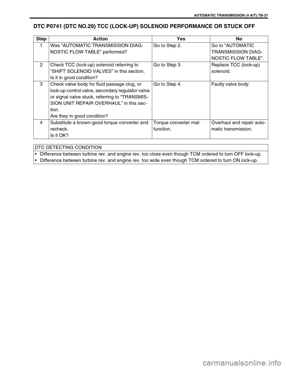
DTC P0741 (DTC NO.29) TCC (LOCK-UP) SOLENOID PERFORMANCE OR STUCK OFF
Step Action Yes No
1Was “AUTOMATIC TRANSMISSION DIAG-
NOSTIC FLOW TABLE” performed?Go to Step 2. Go to “AUTOMATIC
TRANSMISSION DIAG-
NOSTIC FLOW TABLE”.
2 Check TCC (lock-up) solenoid referring to
“SHIFT SOLENOID VALVES” in this section.
Is it in good condition?Go to Step 3. Replace TCC (lock-up)
solenoid.
3 Check valve body for fluid passage clog, or
lock-up control valve, secondary regulator valve
or signal valve stuck, referring to “TRANSMIS-
SION UNIT REPAIR OVERHAUL” in this sec-
tion.
Are they in good condition?Go to Step 4. Faulty valve body.
4 Substitute a known-good torque converter and
recheck.
Is it OK?Torque converter mal-
function.Overhaul and repair auto-
matic transmission.
DTC DETECTING CONDITION
Difference between turbine rev. and engine rev. too close even though TCM ordered to turn OFF lock-up.
Difference between turbine rev. and engine rev. too wide even though TCM ordered to turn ON lock-up.
Page 83 of 447
AUTOMATIC TRANSMISSION (4 A/T) 7B-41
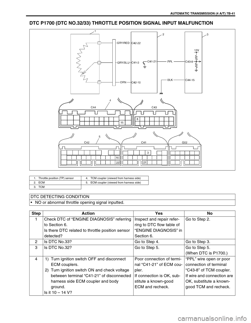
DTC P1700 (DTC NO.32/33) THROTTLE POSITION SIGNAL INPUT MALFUNCTION
1. Throttle position (TP) sensor 4. TCM coupler (viewed from harness side)
2. ECM 5. ECM coupler (viewed from harness side)
3. TCM
DTC DETECTING CONDITION
NO or abnormal throttle opening signal inputted.
Step Action Yes No
1 Check DTC of “ENGINE DIAGNOSIS” referring
to Section 6.
Is there DTC related to throttle position sensor
detected?Inspect and repair refer-
ring to DTC flow table of
“ENGINE DIAGNOSIS” in
Section 6.Go to Step 2.
2 Is DTC No.33? Go to Step 4. Go to Step 3.
3 Is DTC No.32? Go to Step 5. Go to Step 5.
(When DTC is P1700.)
4 1) Turn ignition switch OFF and disconnect
ECM couplers.
2) Turn ignition switch ON and check voltage
between terminal “C41-21” of disconnected
harness side ECM coupler and body
ground.
Is it 10 – 14 V?Poor connection of termi-
nal “C41-21” of ECM cou-
pler.
If connection is OK, sub-
stitute a known-good
ECM and recheck.“PPL” wire open or poor
connection of terminal
“C43-8” of TCM coupler.
If wire and connection are
OK, substitute a known-
good TCM and recheck.
Page 87 of 447
AUTOMATIC TRANSMISSION (4 A/T) 7B-45
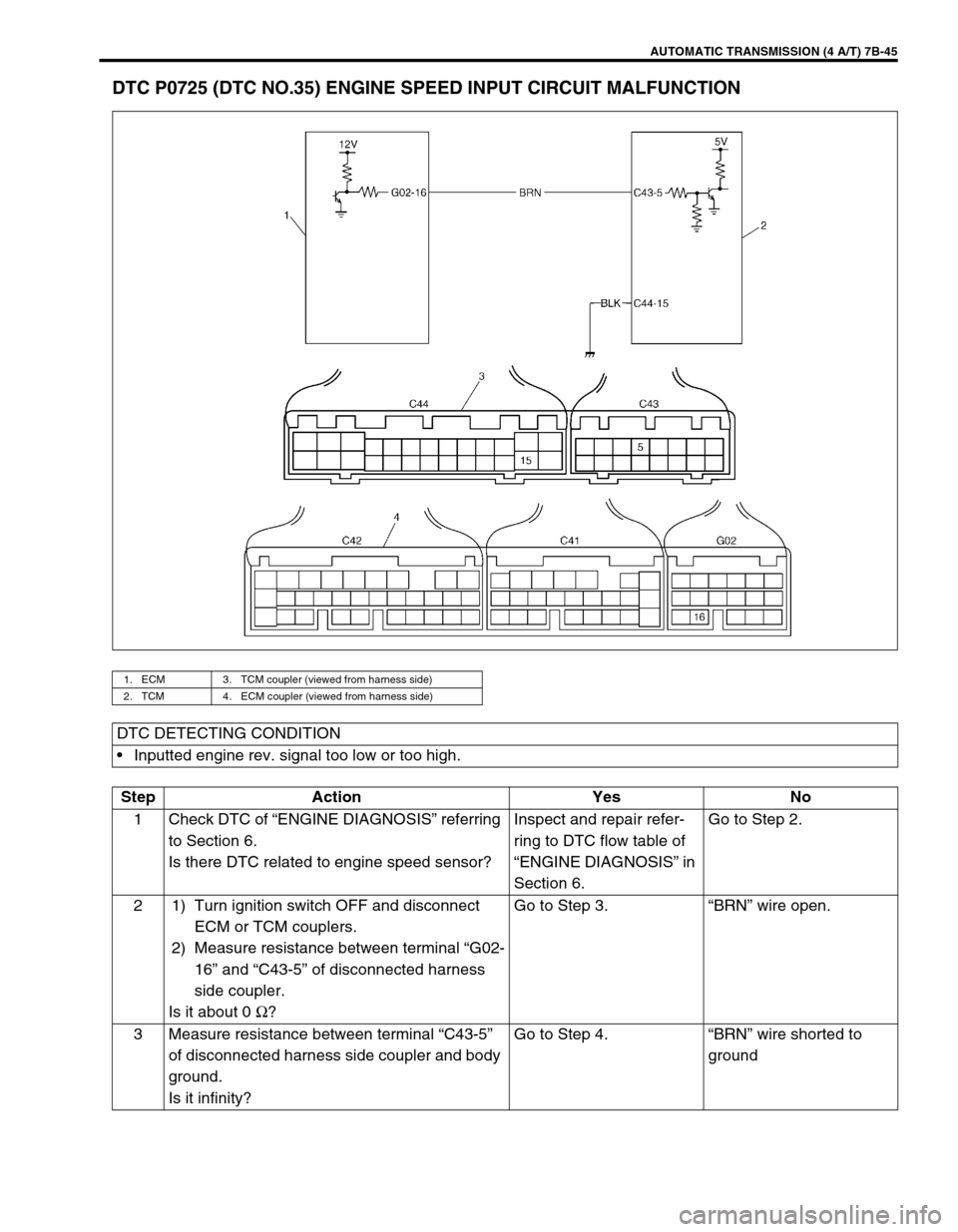
DTC P0725 (DTC NO.35) ENGINE SPEED INPUT CIRCUIT MALFUNCTION
1. ECM 3. TCM coupler (viewed from harness side)
2. TCM 4. ECM coupler (viewed from harness side)
DTC DETECTING CONDITION
Inputted engine rev. signal too low or too high.
Step Action Yes No
1 Check DTC of “ENGINE DIAGNOSIS” referring
to Section 6.
Is there DTC related to engine speed sensor?Inspect and repair refer-
ring to DTC flow table of
“ENGINE DIAGNOSIS” in
Section 6.Go to Step 2.
2 1) Turn ignition switch OFF and disconnect
ECM or TCM couplers.
2) Measure resistance between terminal “G02-
16” and “C43-5” of disconnected harness
side coupler.
Is it about 0 Ω
?Go to Step 3.“BRN” wire open.
3 Measure resistance between terminal “C43-5”
of disconnected harness side coupler and body
ground.
Is it infinity?Go to Step 4.“BRN” wire shorted to
ground
Page 93 of 447
AUTOMATIC TRANSMISSION (4 A/T) 7B-51
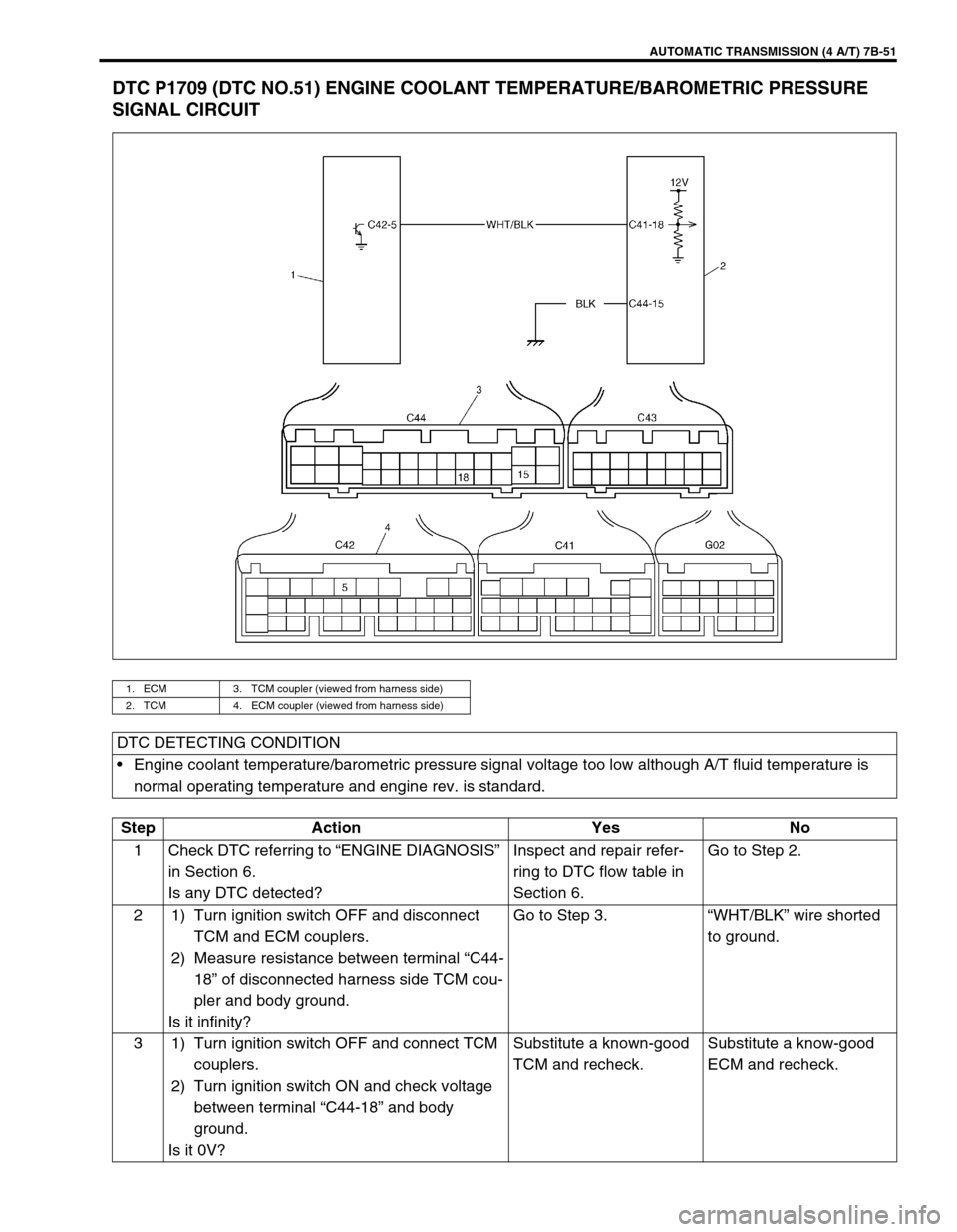
DTC P1709 (DTC NO.51) ENGINE COOLANT TEMPERATURE/BAROMETRIC PRESSURE
SIGNAL CIRCUIT
1. ECM 3. TCM coupler (viewed from harness side)
2. TCM 4. ECM coupler (viewed from harness side)
DTC DETECTING CONDITION
Engine coolant temperature/barometric pressure signal voltage too low although A/T fluid temperature is
normal operating temperature and engine rev. is standard.
Step Action Yes No
1 Check DTC referring to “ENGINE DIAGNOSIS”
in Section 6.
Is any DTC detected?Inspect and repair refer-
ring to DTC flow table in
Section 6.Go to Step 2.
2 1) Turn ignition switch OFF and disconnect
TCM and ECM couplers.
2) Measure resistance between terminal “C44-
18” of disconnected harness side TCM cou-
pler and body ground.
Is it infinity?Go to Step 3.“WHT/BLK” wire shorted
to ground.
3 1) Turn ignition switch OFF and connect TCM
couplers.
2) Turn ignition switch ON and check voltage
between terminal “C44-18” and body
ground.
Is it 0V?Substitute a known-good
TCM and recheck.Substitute a know-good
ECM and recheck.
Page 98 of 447
7B-56 AUTOMATIC TRANSMISSION (4 A/T)
FLUID LEVEL AT ROOM TEMPERATURE
INSPECTION
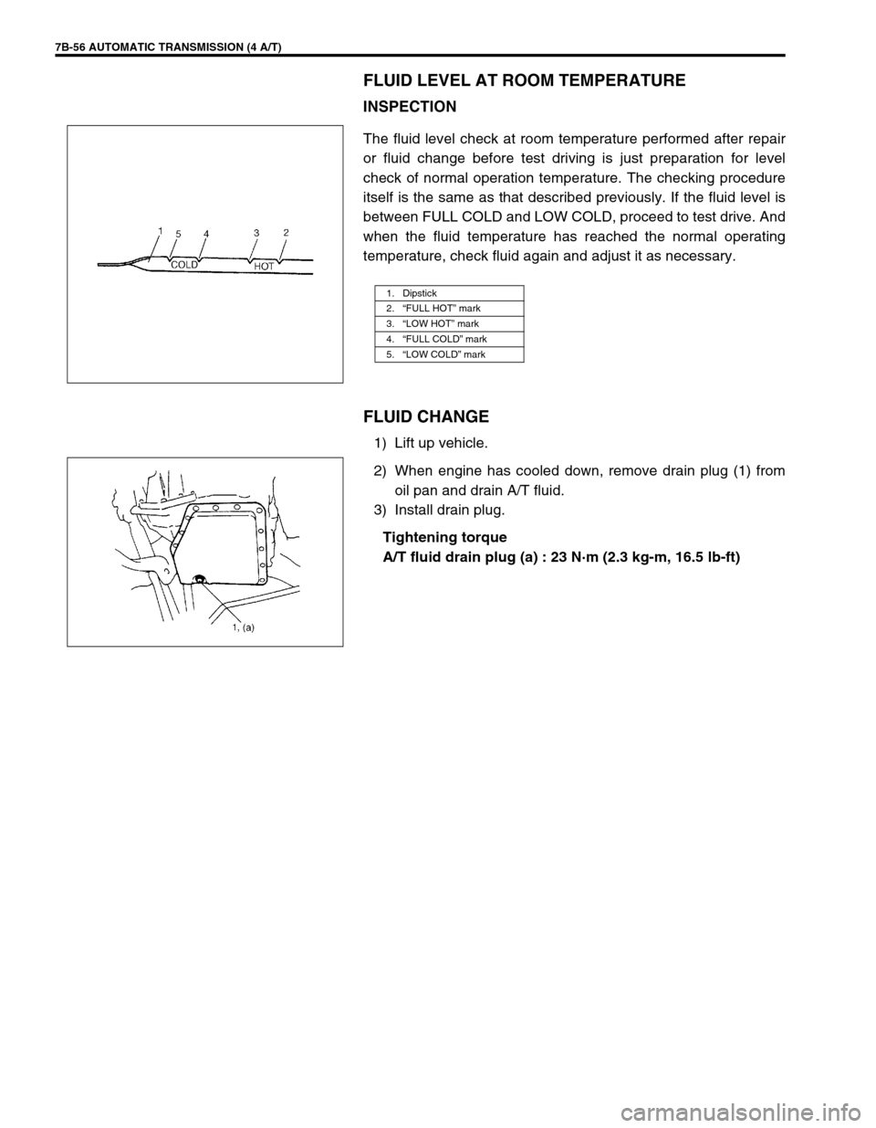
The fluid level check at room temperature performed after repair
or fluid change before test driving is just preparation for level
check of normal operation temperature. The checking procedure
itself is the same as that described previously. If the fluid level is
between FULL COLD and LOW COLD, proceed to test drive. And
when the fluid temperature has reached the normal operating
temperature, check fluid again and adjust it as necessary.
FLUID CHANGE
1) Lift up vehicle.
2) When engine has cooled down, remove drain plug (1) from
oil pan and drain A/T fluid.
3) Install drain plug.
Tightening torque
A/T fluid drain plug (a) : 23 N·m (2.3 kg-m, 16.5 lb-ft)
1. Dipstick
2.“FULL HOT” mark
3.“LOW HOT” mark
4.“FULL COLD” mark
5.“LOW COLD” mark
Page 111 of 447
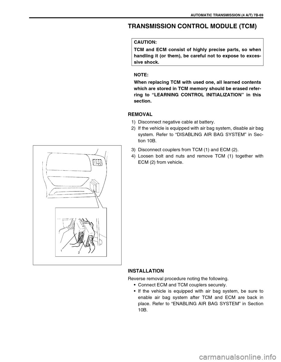
AUTOMATIC TRANSMISSION (4 A/T) 7B-69
TRANSMISSION CONTROL MODULE (TCM)
REMOVAL
1) Disconnect negative cable at battery.
2) If the vehicle is equipped with air bag system, disable air bag
system. Refer to “DISABLING AIR BAG SYSTEM” in Sec-
tion 10B.
3) Disconnect couplers from TCM (1) and ECM (2).
4) Loosen bolt and nuts and remove TCM (1) together with
ECM (2) from vehicle.
INSTALLATION
Reverse removal procedure noting the following.
Connect ECM and TCM couplers securely.
If the vehicle is equipped with air bag system, be sure to
enable air bag system after TCM and ECM are back in
place. Refer to “ENABLING AIR BAG SYSTEM” in Section
10B. CAUTION:
TCM and ECM consist of highly precise parts, so when
handling it (or them), be careful not to expose to exces-
sive shock.
NOTE:
When replacing TCM with used one, all learned contents
which are stored in TCM memory should be erased refer-
ring to “LEARNING CONTROL INITIALIZATION” in this
section.