Air SUZUKI SWIFT 2000 1.G Transmission Service Owner's Guide
[x] Cancel search | Manufacturer: SUZUKI, Model Year: 2000, Model line: SWIFT, Model: SUZUKI SWIFT 2000 1.GPages: 447, PDF Size: 10.54 MB
Page 137 of 447

AUTOMATIC TRANSMISSION (4 A/T) 7B-95
10) Attach special tool (B) to dial gauge (2) and set them on the
lowest clutch plate.
Special tool
(B) : 09952-06010
11) Measure piston stroke by blowing compressed air (4 kg/cm
2,
57 psi) as shown in figure.
If the piston stroke is out of specification, replace clutch
discs, plates and flange.
Front clutch piston stroke
: 1.46 – 1.64 mm (0.0575 – 0.0646 in.)
REAR CLUTCH (C1 CLUTCH)
1. Front clutch assembly
3. Air gun
1. Input shaft oil seal ring
: Apply grease 99000-25030 to all over surface.8. Clutch plate
2. Input shaft subassembly 9. Clutch disc
3. D-ring
: Apply grease 99000-25030 to all over surface.10. Clutch flange
4. Rear clutch piston
: Apply grease 99000-25030 to the lip of the piston.11. Snap ring
5. Rear clutch return spring seat Apply automatic transmission fluid.
6. Rear clutch balancer Do not reuse.
7. Shaft snap ring
Page 138 of 447

7B-96 AUTOMATIC TRANSMISSION (4 A/T)
DISASSEMBLY
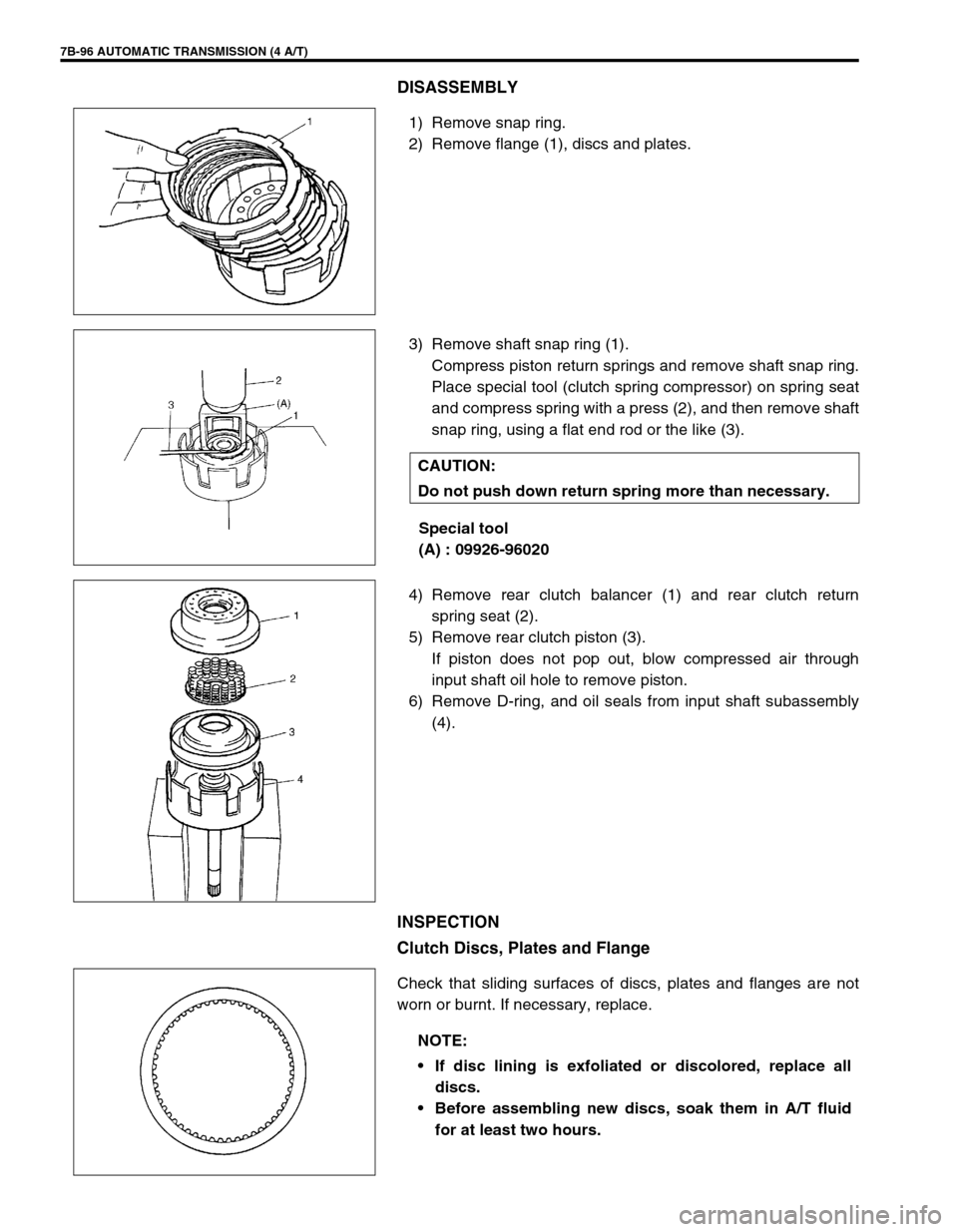
1) Remove snap ring.
2) Remove flange (1), discs and plates.
3) Remove shaft snap ring (1).
Compress piston return springs and remove shaft snap ring.
Place special tool (clutch spring compressor) on spring seat
and compress spring with a press (2), and then remove shaft
snap ring, using a flat end rod or the like (3).
Special tool
(A) : 09926-96020
4) Remove rear clutch balancer (1) and rear clutch return
spring seat (2).
5) Remove rear clutch piston (3).
If piston does not pop out, blow compressed air through
input shaft oil hole to remove piston.
6) Remove D-ring, and oil seals from input shaft subassembly
(4).
INSPECTION
Clutch Discs, Plates and Flange
Check that sliding surfaces of discs, plates and flanges are not
worn or burnt. If necessary, replace.
CAUTION:
Do not push down return spring more than necessary.
NOTE:
If disc lining is exfoliated or discolored, replace all
discs.
Before assembling new discs, soak them in A/T fluid
for at least two hours.
Page 141 of 447

AUTOMATIC TRANSMISSION (4 A/T) 7B-99
7) Place special tool (C) on soft jawed vise (2) with wider open-
ing (1) facing up.
Special tool
(C) : 09926-26040
8) Place rear clutch assembly (1) on special tool (C).
9) Set dial gauge (2) on the top of clutch flange (3) and mea-
sure clearance by blowing compressed air (4 kg/cm
2, 57 psi)
as shown in figure.
If the clearance is out of specification, replace clutch discs,
plates and flange.
Rear clutch disc clearance
: 0.80 – 1.40 mm (0.031 – 0.055 in.)
10) Attach special tool (B) to dial gauge (4) and set them on the
lowest clutch plate (2).
Special tool
(B) : 09952-06010
11) Measure piston stroke by blowing compressed air (4 kg/cm
2,
57 psi) as shown in figure.
If the piston stroke is out of specification, replace clutch
discs, plates and flange.
Rear clutch piston stroke
: 1.93 – 2.13 mm (0.076 – 0.084 in.)
1. Rear clutch assembly
3. Air gun
Page 143 of 447

AUTOMATIC TRANSMISSION (4 A/T) 7B-101
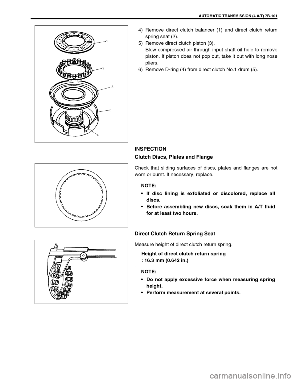
4) Remove direct clutch balancer (1) and direct clutch return
spring seat (2).
5) Remove direct clutch piston (3).
Blow compressed air through input shaft oil hole to remove
piston. If piston does not pop out, take it out with long nose
pliers.
6) Remove D-ring (4) from direct clutch No.1 drum (5).
INSPECTION
Clutch Discs, Plates and Flange
Check that sliding surfaces of discs, plates and flanges are not
worn or burnt. If necessary, replace.
Direct Clutch Return Spring Seat
Measure height of direct clutch return spring.
Height of direct clutch return spring
: 16.3 mm (0.642 in.)
.
NOTE:
If disc lining is exfoliated or discolored, replace all
discs.
Before assembling new discs, soak them in A/T fluid
for at least two hours.
NOTE:
Do not apply excessive force when measuring spring
height.
Perform measurement at several points.
Page 145 of 447

AUTOMATIC TRANSMISSION (4 A/T) 7B-103
6) Install snap ring (1).
7) Place special tool (A) on soft jawed vise (1) and install 2 oil
seal rings on special tool.
Special tool
(A) : 09926-26050
(B) : Rear cover seal ring 24742-78F10 SUZUKI GENUINE
PARTS
8) Place direct clutch assembly (1) on special tool (A).
9) Set dial gauge (4) on the top of clutch flange (2) and mea-
sure clearance by blowing compressed air (4 kg/cm
2, 57 psi)
as shown in figure.
If the clearance is out of specification, replace clutch discs,
plates and flange.
Direct clutch disc clearance
: 0.50 – 1.04 mm (0.0197 – 0.0409 in.) NOTE:
Make sure that the ends of the snap ring do not come to
the opening of the front clutch No.1 drum.
NOTE:
Rear cover seal set has two seal rings in a set.
Do not use the seal rings removed from rear cover. It is
not necessary to remove seal rings from special tool
once installed.
3. Air gun
Page 146 of 447

7B-104 AUTOMATIC TRANSMISSION (4 A/T)
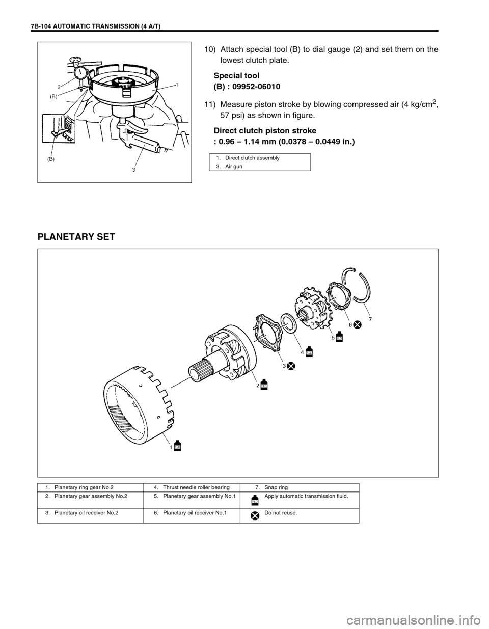
10) Attach special tool (B) to dial gauge (2) and set them on the
lowest clutch plate.
Special tool
(B) : 09952-06010
11) Measure piston stroke by blowing compressed air (4 kg/cm
2,
57 psi) as shown in figure.
Direct clutch piston stroke
: 0.96 – 1.14 mm (0.0378 – 0.0449 in.)
PLANETARY SET
1. Direct clutch assembly
3. Air gun
1. Planetary ring gear No.2 4. Thrust needle roller bearing 7. Snap ring
2. Planetary gear assembly No.2 5. Planetary gear assembly No.1 Apply automatic transmission fluid.
3. Planetary oil receiver No.2 6. Planetary oil receiver No.1 Do not reuse.
Page 157 of 447

AUTOMATIC TRANSMISSION (4 A/T) 7B-115
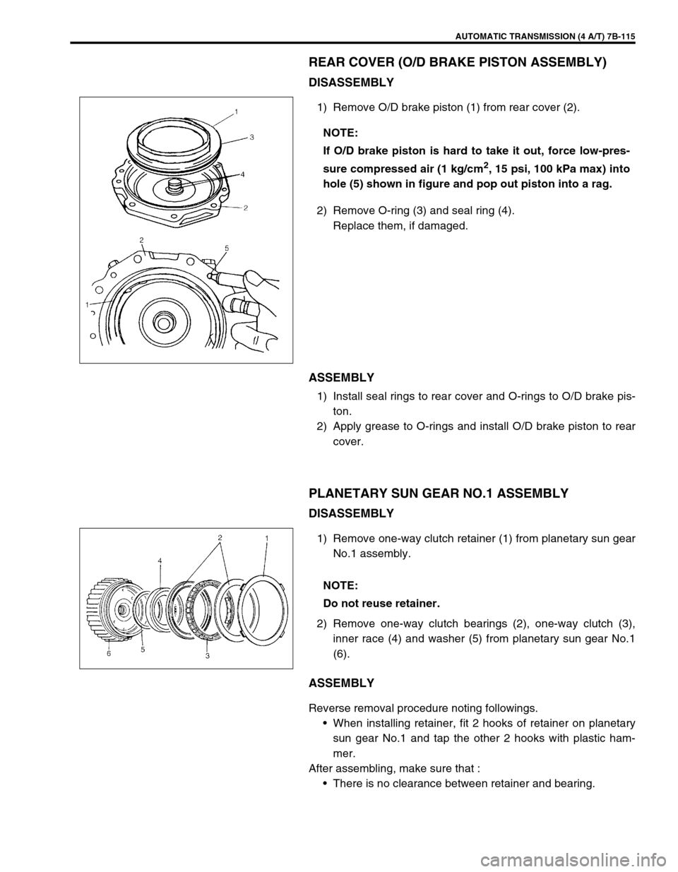
REAR COVER (O/D BRAKE PISTON ASSEMBLY)
DISASSEMBLY
1) Remove O/D brake piston (1) from rear cover (2).
2) Remove O-ring (3) and seal ring (4).
Replace them, if damaged.
ASSEMBLY
1) Install seal rings to rear cover and O-rings to O/D brake pis-
ton.
2) Apply grease to O-rings and install O/D brake piston to rear
cover.
PLANETARY SUN GEAR NO.1 ASSEMBLY
DISASSEMBLY
1) Remove one-way clutch retainer (1) from planetary sun gear
No.1 assembly.
2) Remove one-way clutch bearings (2), one-way clutch (3),
inner race (4) and washer (5) from planetary sun gear No.1
(6).
ASSEMBLY
Reverse removal procedure noting followings.
When installing retainer, fit 2 hooks of retainer on planetary
sun gear No.1 and tap the other 2 hooks with plastic ham-
mer.
After assembling, make sure that :
There is no clearance between retainer and bearing. NOTE:
If O/D brake piston is hard to take it out, force low-pres-
sure compressed air (1 kg/cm
2, 15 psi, 100 kPa max) into
hole (5) shown in figure and pop out piston into a rag.
NOTE:
Do not reuse retainer.
Page 160 of 447

7B-118 AUTOMATIC TRANSMISSION (4 A/T)
2) Install new oil seal to transmission case.
Use special tool to press-fit oil seal until oil seal end face is
flush with transmission case end face.
Special tool
(F) : 09913-75510
UNIT ASSEMBLY
CAUTION:
Automatic transmission consists of highly precise parts. As even a flaw in a small part may cause
oil leakage or decrease in function, check each part carefully before installation.
Clean all parts with compressed air. Never use wiping cloths or rags.
Before assembling new clutch discs and brake band, soak them in automatic transmission fluid for
at least 2 hours.
Be sure to use new gaskets and O-rings.
Lubricate O-rings with automatic transmission fluid.
Apply automatic transmission fluid on sliding or rotating surfaces of the parts before assembly.
Use yellow petrolatum grease or Suzuki Super Grease C to retain parts in place.
Be sure to install thrust bearings and races in correct direction and position.
Make sure that snap ring ends are not aligned with one of cutouts and are installed in groove cor-
rectly.
Do not use adhesive cements on gaskets and similar parts.
Be sure to torque each bolt and nut to specification.
Page 163 of 447

AUTOMATIC TRANSMISSION (4 A/T) 7B-121
12) Measure 1st & 2nd brake (B1) stroke and clearance in fol-
lowing manner.
Set the dial gauge (1) to 1st & 2nd brake (B1) piston as
shown. Blow compressed air into hole (4) shown in figure.
Then measure the difference as the compressed air is blown
in.
1st & 2nd brake (B1) piston stroke
Standard : 1.79 – 2.01 mm (0.0705 – 0.0791 in.)
Set the dial gauge (1) on the top-most brake disc (5).
Blow compressed air into the hole (4) shown in figure.
Measure the difference. Call this value (A).
If the measured value (s) is (are) out of specification, replace
brake discs, plates and flange.
1st & 2nd brake (B1) disc clearance
Standard : 1.31 – 1.96 mm (0.0516 – 0.0772 in.)
\
13) Install O/D brake (B0) return spring seat (4), return spring (3)
and then retainer (2).
14) While compressing retainer (2), install snap ring (1).
2. Tip of dial gauge on B1 brake piston
3. Air gun
CAUTION:
Position return spring (3) to be centered so that rear
cover not be caught.
Page 165 of 447

AUTOMATIC TRANSMISSION (4 A/T) 7B-123
19) Measure the clearance of O/D brake (B0) in the following
manner.
Blow compressed air into hole (4) shown in figure to activate
1st & 2nd brake (B1) piston, then measure the distance
between the top of O/D brake (B0) plate and the transmis-
sion case – rear cover mating surface.
Call this value (A).
((A) = The value on vernier caliper – width of straight edge )
Measure the distance from top of O/D brake (B0) piston (on
rear cover) to rear cover – transmission case mating surface.
Call this value (B).
Clearance = (A) – (B) + 0.4
O/D brake (B0) clearance
Standard : 0.80 – 1.40 mm (0.0315 – 0.0551 in.)
20) If the obtained value is out of standard value, replace brake
disc and plate.
21) Install O/D brake piston adapter (1) thrust needle roller bear-
ing (2) and direct clutch (C0) assembly (3).
1. Straight edge
2. Vernier caliper
3. Rear cover assembly (with B0 piston)
5. Air gun
6. O/D brake piston adapter