Air SUZUKI SWIFT 2000 1.G Transmission Service Owner's Manual
[x] Cancel search | Manufacturer: SUZUKI, Model Year: 2000, Model line: SWIFT, Model: SUZUKI SWIFT 2000 1.GPages: 447, PDF Size: 10.54 MB
Page 112 of 447
7B-70 AUTOMATIC TRANSMISSION (4 A/T)
LEARNING CONTROL INITIALIZATION
When one or more operations such as shown below are per-
formed, all learned contents which are stored in TCM memory
should be erased after the operations.
Replacing transmission with new or used one.
Repairing transmission partially by replacing any brake com-
ponent parts with new and/or used brake disc(s), plate(s)
and/or flange.
Repairing transmission partially by replacing any clutch com-
ponent parts with new and/or used clutch disc(s), plate(s)
and/or flange.
Replacing TCM with used one.
1) Turn ignition switch ON, leaving engine OFF.
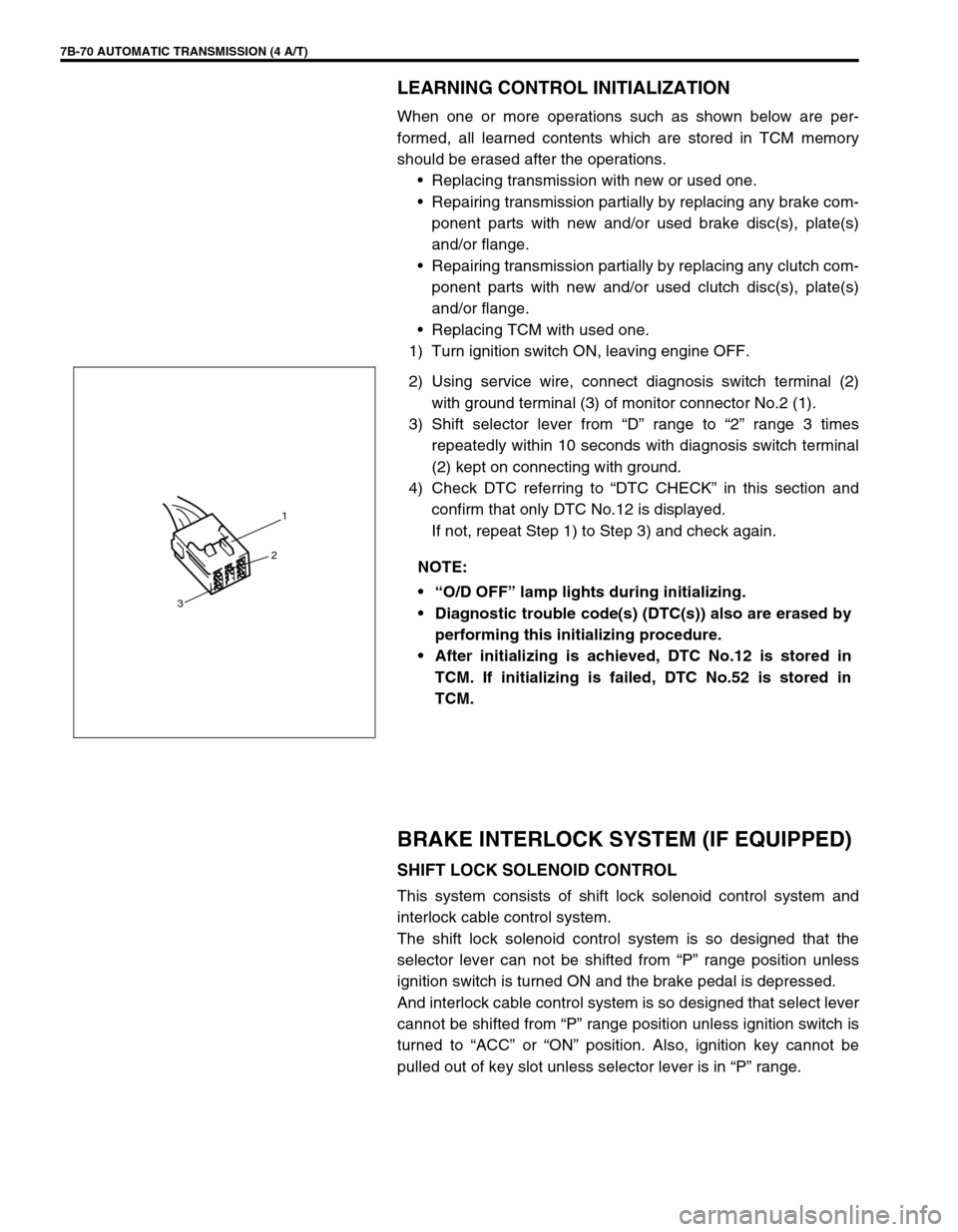
2) Using service wire, connect diagnosis switch terminal (2)
with ground terminal (3) of monitor connector No.2 (1).
3) Shift selector lever from “D” range to “2” range 3 times
repeatedly within 10 seconds with diagnosis switch terminal
(2) kept on connecting with ground.
4) Check DTC referring to “DTC CHECK” in this section and
confirm that only DTC No.12 is displayed.
If not, repeat Step 1) to Step 3) and check again.
BRAKE INTERLOCK SYSTEM (IF EQUIPPED)
SHIFT LOCK SOLENOID CONTROL
This system consists of shift lock solenoid control system and
interlock cable control system.
The shift lock solenoid control system is so designed that the
selector lever can not be shifted from “P” range position unless
ignition switch is turned ON and the brake pedal is depressed.
And interlock cable control system is so designed that select lever
cannot be shifted from “P” range position unless ignition switch is
turned to “ACC” or “ON” position. Also, ignition key cannot be
pulled out of key slot unless selector lever is in “P” range. NOTE:
“O/D OFF” lamp lights during initializing.
Diagnostic trouble code(s) (DTC(s)) also are erased by
performing this initializing procedure.
After initializing is achieved, DTC No.12 is stored in
TCM. If initializing is failed, DTC No.52 is stored in
TCM.
1
2
3
Page 115 of 447
AUTOMATIC TRANSMISSION (4 A/T) 7B-73
REMOVAL
1) Disconnect negative cable at battery and disable air bag sys-
tem, referring to “DISABLING AIR BAG SYSTEMS” in Sec-
tion 10B (if equipped).
2) Remove steering column hole cover and steering column
cover.
3) Remove steering column mounting bolts and nuts.
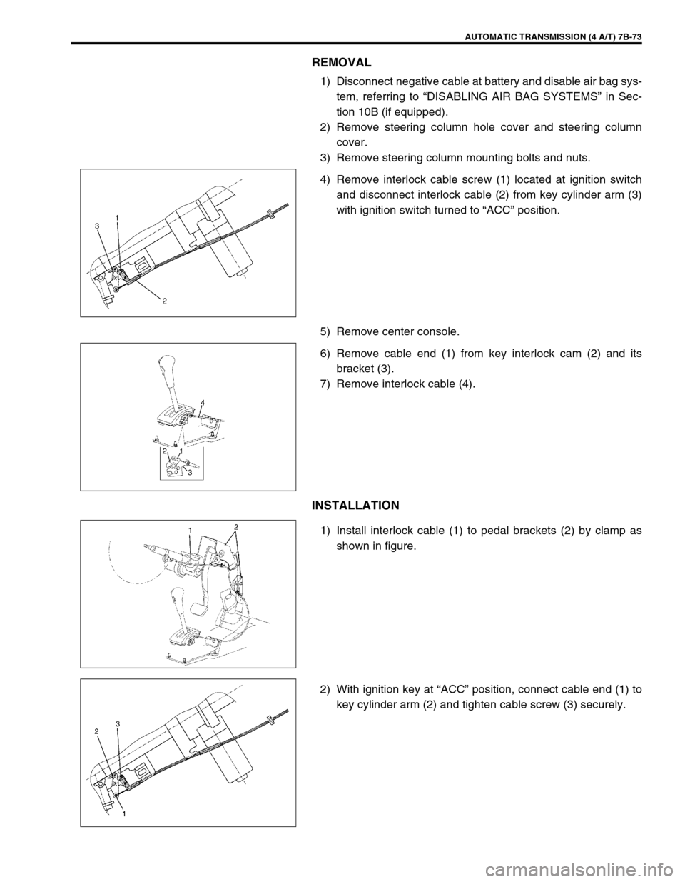
4) Remove interlock cable screw (1) located at ignition switch
and disconnect interlock cable (2) from key cylinder arm (3)
with ignition switch turned to “ACC” position.
5) Remove center console.
6) Remove cable end (1) from key interlock cam (2) and its
bracket (3).
7) Remove interlock cable (4).
INSTALLATION
1) Install interlock cable (1) to pedal brackets (2) by clamp as
shown in figure.
2) With ignition key at “ACC” position, connect cable end (1) to
key cylinder arm (2) and tighten cable screw (3) securely.
Page 116 of 447

7B-74 AUTOMATIC TRANSMISSION (4 A/T)
3) If selector lever is in “P” range, shift selector lever to other
than “P” range with releasing shift lock referring to “SHIFT
LOCK SOLENOID MANUAL RELEASE” in this section.
4) Install cable end (1) and cable casing cap (2) to key interlock
cam (3) and its bracket (4), then install cable (5) to selector
pad (6).
5) With selector lever set at “P” position, turn ignition key to
“ACC” position and then check for following conditions.
With knob button released, ignition key can be turned from
“ACC” position to “LOCK” position.
With knob button pressed, ignition key cannot be turned from
“ACC” position to “LOCK” position.
6) Install steering column referring to Section 3C.
7) Install steering column hole cover.
8) Install center console.
9) Connect negative cable at battery and enable air bag sys-
tem, referring to “ENABLING AIR BAG SYSTEM” in Section
10B (if equipped).
Page 117 of 447
AUTOMATIC TRANSMISSION (4 A/T) 7B-75
TRANSMISSION UNIT REPAIR OVERHAUL
NOTE:
When transmission is replaced, or when clutch or brake disc, plate and/or flange is changed to new
and/or used one, all learned contents which are stored in TCM memory should be erased referring to
“LEARNING CONTROL INITIALIZATION” in this section.
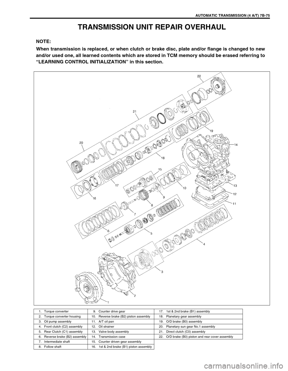
1. Torque converter 9. Counter drive gear 17. 1st & 2nd brake (B1) assembly
2. Torque converter housing 10. Reverse brake (B2) piston assembly 18. Planetary gear assembly
3. Oil pump assembly 11. A/T oil pan 19. O/D brake (B0) assembly
4. Front clutch (C2) assembly 12. Oil strainer 20. Planetary sun gear No.1 assembly
5. Rear Clutch (C1) assembly 13. Valve body assembly 21. Direct clutch (C0) assembly
6. Reverse brake (B2) assembly 14. Transmission case 22. O/D brake (B0) piston and rear cover assembly
7. Intermediate shaft 15. Counter driven gear assembly
8. Follow shaft 16. 1st & 2nd brake (B1) piston assembly
Page 122 of 447
7B-80 AUTOMATIC TRANSMISSION (4 A/T)
12) Disconnect couplers from solenoid valves, and transmission
temperature sensor.
Remove transmission temperature sensor.
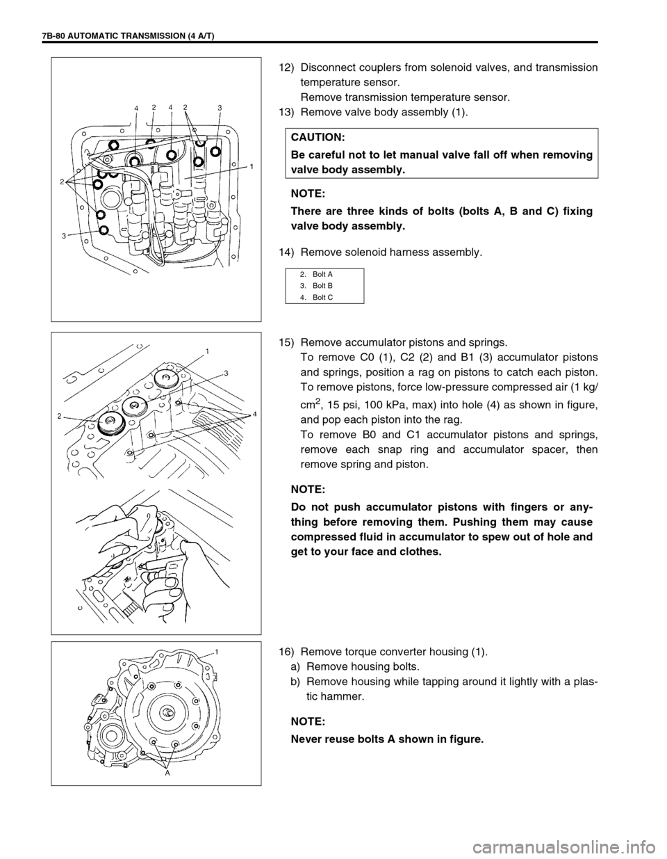
13) Remove valve body assembly (1).
14) Remove solenoid harness assembly.
15) Remove accumulator pistons and springs.
To remove C0 (1), C2 (2) and B1 (3) accumulator pistons
and springs, position a rag on pistons to catch each piston.
To remove pistons, force low-pressure compressed air (1 kg/
cm
2, 15 psi, 100 kPa, max) into hole (4) as shown in figure,
and pop each piston into the rag.
To remove B0 and C1 accumulator pistons and springs,
remove each snap ring and accumulator spacer, then
remove spring and piston.
16) Remove torque converter housing (1).
a) Remove housing bolts.
b) Remove housing while tapping around it lightly with a plas-
tic hammer. CAUTION:
Be careful not to let manual valve fall off when removing
valve body assembly.
NOTE:
There are three kinds of bolts (bolts A, B and C) fixing
valve body assembly.
2. Bolt A
3. Bolt B
4. Bolt C
NOTE:
Do not push accumulator pistons with fingers or any-
thing before removing them. Pushing them may cause
compressed fluid in accumulator to spew out of hole and
get to your face and clothes.
NOTE:
Never reuse bolts A shown in figure.
Page 127 of 447

AUTOMATIC TRANSMISSION (4 A/T) 7B-85
35) Remove planetary sun gear No.2 (1) and thrust needle roller
bearing (2).
36) Remove snap ring, then remove brake flange and disc.
37) Remove snap ring, then remove brake discs and plates (B1
brake).
38) Remove snap ring (1), then O/D brake return spring seat (2),
return spring (3) and spring retainer (4).
39) Remove snap ring (1) then remove 1st & 2nd brake piston
return spring subassembly (2) and 1st & 2nd brake piston
(3).
To remove 1st & 2nd brake piston, force low-pressure com-
pressed air (1 kg/cm
2, 15 psi, 100 kPa, max) into hole (5)
shown in figure and pop out 1st & 2nd brake piston into a
rag.
4. Air gun
Page 128 of 447

7B-86 AUTOMATIC TRANSMISSION (4 A/T)
40) Remove counter drive gear (1).
41) Use hydraulic press (8) and special tool to compress wave
spring (4), then remove snap ring (1).
Special tool
(A) : 09926-96040
42) Remove reverse brake piston seat (3), wave spring (4) and
reverse brake piston (5).
To remove reverse brake piston, force low-pressure com-
press air (1 kg/cm
2, 15 psi, 100 kPa, max) into hole (7)
shown in figure, and pop out piston into a rag.
NOTE:
Do not compress wave spring more than necessary.
Do not reuse snap ring (1).
2. Flat end rod or the like
6. Air gun
Page 130 of 447
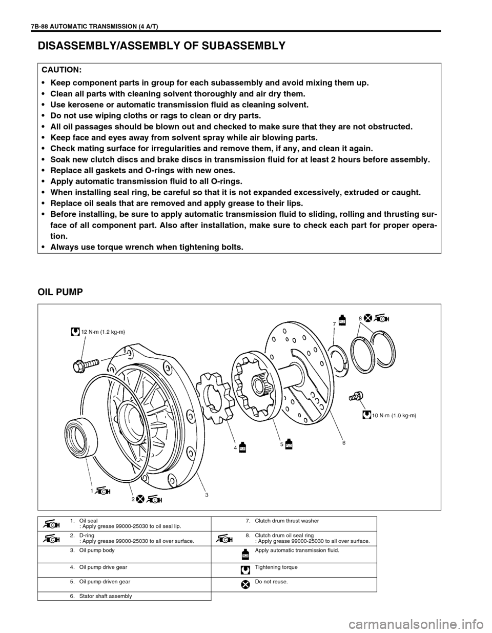
7B-88 AUTOMATIC TRANSMISSION (4 A/T)
DISASSEMBLY/ASSEMBLY OF SUBASSEMBLY
OIL PUMP
CAUTION:
Keep component parts in group for each subassembly and avoid mixing them up.
Clean all parts with cleaning solvent thoroughly and air dry them.
Use kerosene or automatic transmission fluid as cleaning solvent.
Do not use wiping cloths or rags to clean or dry parts.
All oil passages should be blown out and checked to make sure that they are not obstructed.
Keep face and eyes away from solvent spray while air blowing parts.
Check mating surface for irregularities and remove them, if any, and clean it again.
Soak new clutch discs and brake discs in transmission fluid for at least 2 hours before assembly.
Replace all gaskets and O-rings with new ones.
Apply automatic transmission fluid to all O-rings.
When installing seal ring, be careful so that it is not expanded excessively, extruded or caught.
Replace oil seals that are removed and apply grease to their lips.
Before installing, be sure to apply automatic transmission fluid to sliding, rolling and thrusting sur-
face of all component part. Also after installation, make sure to check each part for proper opera-
tion.
Always use torque wrench when tightening bolts.
1. Oil seal
: Apply grease 99000-25030 to oil seal lip.7. Clutch drum thrust washer
2. D-ring
: Apply grease 99000-25030 to all over surface. 8. Clutch drum oil seal ring
: Apply grease 99000-25030 to all over surface.
3. Oil pump body Apply automatic transmission fluid.
4. Oil pump drive gear Tightening torque
5. Oil pump driven gear Do not reuse.
6. Stator shaft assembly
Page 134 of 447

7B-92 AUTOMATIC TRANSMISSION (4 A/T)
4) Remove front clutch balancer (1) and front clutch return
spring seat (2).
5) Remove front clutch piston (3).
Blow compressed air through input shaft oil hole to remove
piston. If piston does not pop out, take it out with long nose
pliers.
6) Remove D-ring (4) from front clutch No.1 drum (5).
INSPECTION
Clutch Discs, Plates and Flange
Check that sliding surfaces of discs, plates and flanges are not
worn or burnt. If necessary, replace.
Front Clutch Return Spring Seat
Measure height of front clutch return spring.
Height of front clutch return spring
: 14.85 mm (0.585 in.)
Front Clutch Piston Lip and Front Clutch Balancer Lip
Check each lip for wear, deformation, cut, and/or hardening. If
necessary, replace.
NOTE:
If disc lining is exfoliated or discolored, replace all
discs.
Before assembling new discs, soak them in A/T fluid
for at least two hours.
NOTE:
Do not apply excessive force when measuring spring
height.
Perform measurement at several points.
Page 136 of 447

7B-94 AUTOMATIC TRANSMISSION (4 A/T)
6) Install snap ring (1).
7) Place special tool (A) on soft jawed vise (1) and install 2 oil
seal rings on special tool.
Special tool
(A) : 09926-26030
(B) : Clutch drum seal ring 22831-83E10 SUZUKI GENUINE
PARTS
8) Place front clutch assembly (1) on special tool (A).
9) Set dial gauge (4) on the top of clutch flange (2) and mea-
sure clearance by blowing compressed air (4 kg/cm
2, 57 psi)
as shown in figure.
If the clearance is out of specification, replace clutch discs,
plates and flange.
Front clutch disc clearance
: 0.47 – 1.14 mm (0.0185 – 0.0448 in.) NOTE:
Make sure that the ends of the snap ring do not come to
the opening of the front clutch No.1 drum.
NOTE:
Clutch drum seal set has two seal rings in a set.
Do not use the seal rings removed from oil pump
assembly. It is not necessary to remove seal rings
from special tool once installed.
3. Air gun