automatic transmission fluid SUZUKI SWIFT 2000 1.G Transmission Service User Guide
[x] Cancel search | Manufacturer: SUZUKI, Model Year: 2000, Model line: SWIFT, Model: SUZUKI SWIFT 2000 1.GPages: 447, PDF Size: 10.54 MB
Page 79 of 447
AUTOMATIC TRANSMISSION (4 A/T) 7B-37
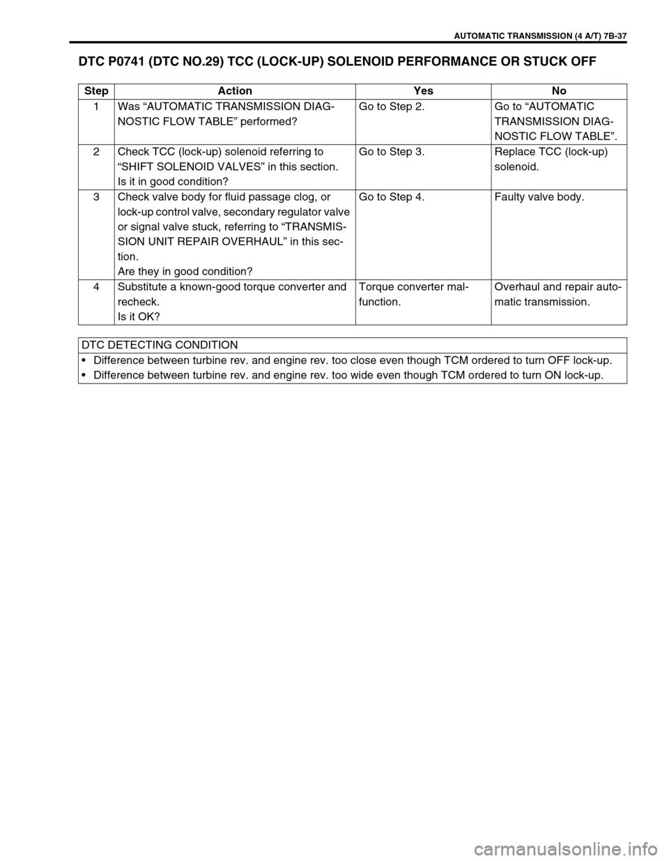
DTC P0741 (DTC NO.29) TCC (LOCK-UP) SOLENOID PERFORMANCE OR STUCK OFF
Step Action Yes No
1Was “AUTOMATIC TRANSMISSION DIAG-
NOSTIC FLOW TABLE” performed?Go to Step 2. Go to “AUTOMATIC
TRANSMISSION DIAG-
NOSTIC FLOW TABLE”.
2 Check TCC (lock-up) solenoid referring to
“SHIFT SOLENOID VALVES” in this section.
Is it in good condition?Go to Step 3. Replace TCC (lock-up)
solenoid.
3 Check valve body for fluid passage clog, or
lock-up control valve, secondary regulator valve
or signal valve stuck, referring to “TRANSMIS-
SION UNIT REPAIR OVERHAUL” in this sec-
tion.
Are they in good condition?Go to Step 4. Faulty valve body.
4 Substitute a known-good torque converter and
recheck.
Is it OK?Torque converter mal-
function.Overhaul and repair auto-
matic transmission.
DTC DETECTING CONDITION
Difference between turbine rev. and engine rev. too close even though TCM ordered to turn OFF lock-up.
Difference between turbine rev. and engine rev. too wide even though TCM ordered to turn ON lock-up.
Page 89 of 447
AUTOMATIC TRANSMISSION (4 A/T) 7B-47
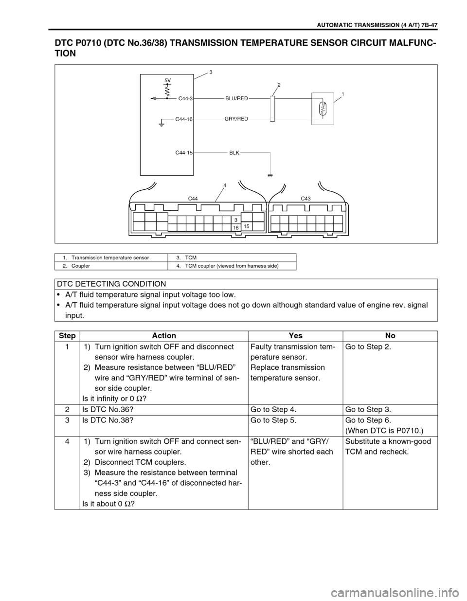
DTC P0710 (DTC No.36/38) TRANSMISSION TEMPERATURE SENSOR CIRCUIT MALFUNC-
TION
1. Transmission temperature sensor 3. TCM
2. Coupler 4. TCM coupler (viewed from harness side)
DTC DETECTING CONDITION
A/T fluid temperature signal input voltage too low.
A/T fluid temperature signal input voltage does not go down although standard value of engine rev. signal
input.
Step Action Yes No
1 1) Turn ignition switch OFF and disconnect
sensor wire harness coupler.
2) Measure resistance between “BLU/RED”
wire and “GRY/RED” wire terminal of sen-
sor side coupler.
Is it infinity or 0 Ω
?Faulty transmission tem-
perature sensor.
Replace transmission
temperature sensor.Go to Step 2.
2 Is DTC No.36? Go to Step 4. Go to Step 3.
3 Is DTC No.38? Go to Step 5. Go to Step 6.
(When DTC is P0710.)
4 1) Turn ignition switch OFF and connect sen-
sor wire harness coupler.
2) Disconnect TCM couplers.
3) Measure the resistance between terminal
“C44-3” and “C44-16” of disconnected har-
ness side coupler.
Is it about 0 Ω
?“BLU/RED” and “GRY/
RED” wire shorted each
other.Substitute a known-good
TCM and recheck.
Page 93 of 447
AUTOMATIC TRANSMISSION (4 A/T) 7B-51
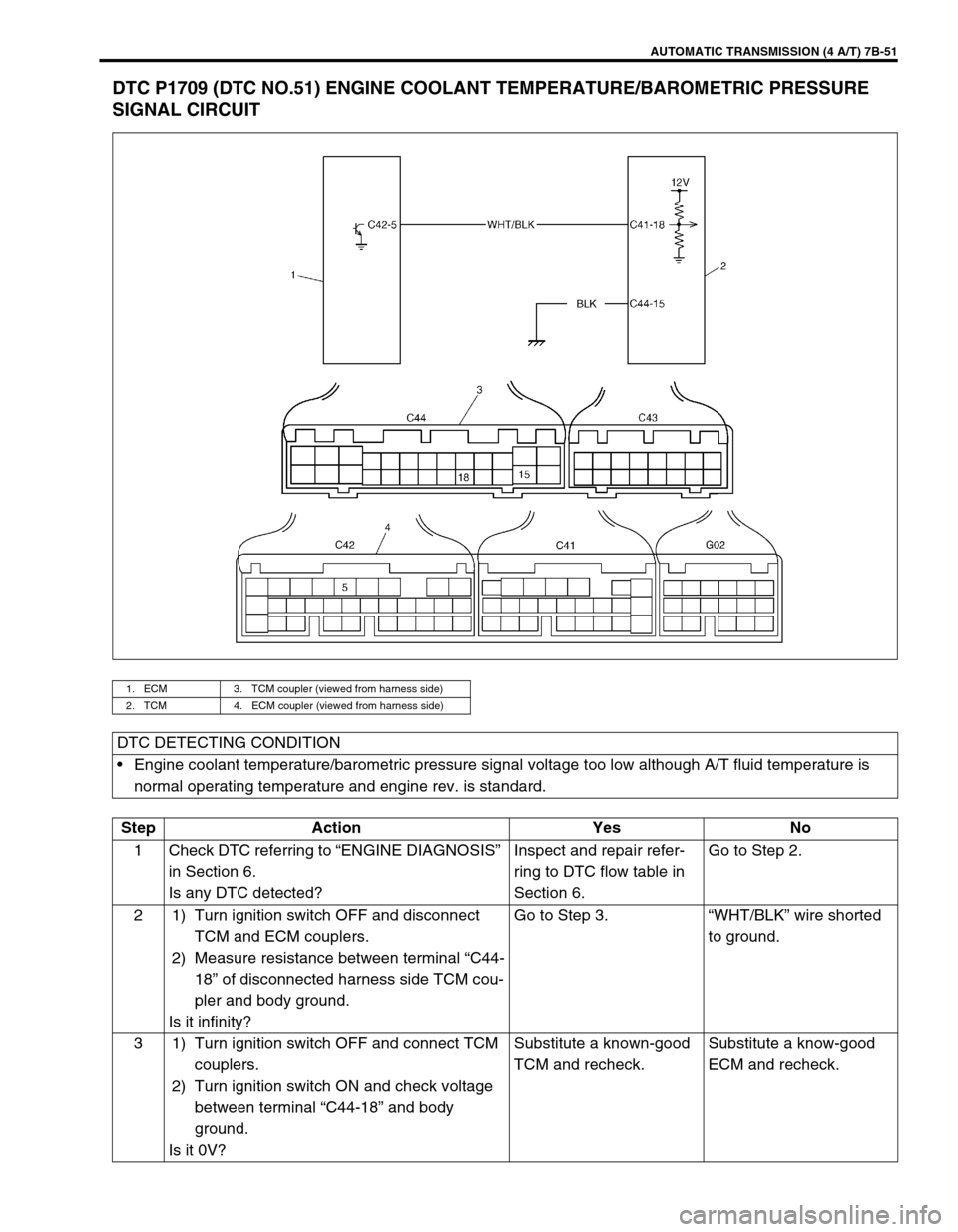
DTC P1709 (DTC NO.51) ENGINE COOLANT TEMPERATURE/BAROMETRIC PRESSURE
SIGNAL CIRCUIT
1. ECM 3. TCM coupler (viewed from harness side)
2. TCM 4. ECM coupler (viewed from harness side)
DTC DETECTING CONDITION
Engine coolant temperature/barometric pressure signal voltage too low although A/T fluid temperature is
normal operating temperature and engine rev. is standard.
Step Action Yes No
1 Check DTC referring to “ENGINE DIAGNOSIS”
in Section 6.
Is any DTC detected?Inspect and repair refer-
ring to DTC flow table in
Section 6.Go to Step 2.
2 1) Turn ignition switch OFF and disconnect
TCM and ECM couplers.
2) Measure resistance between terminal “C44-
18” of disconnected harness side TCM cou-
pler and body ground.
Is it infinity?Go to Step 3.“WHT/BLK” wire shorted
to ground.
3 1) Turn ignition switch OFF and connect TCM
couplers.
2) Turn ignition switch ON and check voltage
between terminal “C44-18” and body
ground.
Is it 0V?Substitute a known-good
TCM and recheck.Substitute a know-good
ECM and recheck.
Page 97 of 447
AUTOMATIC TRANSMISSION (4 A/T) 7B-55
ON-VEHICLE SERVICE
MAINTENANCE SERVICE
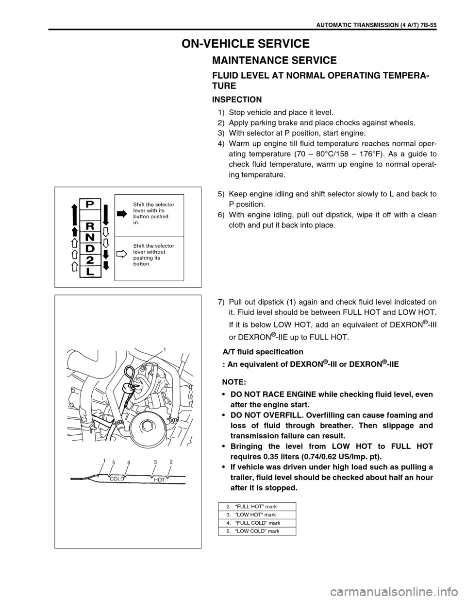
FLUID LEVEL AT NORMAL OPERATING TEMPERA-
TURE
INSPECTION
1) Stop vehicle and place it level.
2) Apply parking brake and place chocks against wheels.
3) With selector at P position, start engine.
4) Warm up engine till fluid temperature reaches normal oper-
ating temperature (70 – 80°C/158 – 176°F). As a guide to
check fluid temperature, warm up engine to normal operat-
ing temperature.
5) Keep engine idling and shift selector slowly to L and back to
P position.
6) With engine idling, pull out dipstick, wipe it off with a clean
cloth and put it back into place.
7) Pull out dipstick (1) again and check fluid level indicated on
it. Fluid level should be between FULL HOT and LOW HOT.
If it is below LOW HOT, add an equivalent of DEXRON
®-III
or DEXRON
®-IIE up to FULL HOT.
A/T fluid specification
: An equivalent of DEXRON
®-III or DEXRON®-IIE
NOTE:
DO NOT RACE ENGINE while checking fluid level, even
after the engine start.
DO NOT OVERFILL. Overfilling can cause foaming and
loss of fluid through breather. Then slippage and
transmission failure can result.
Bringing the level from LOW HOT to FULL HOT
requires 0.35 liters (0.74/0.62 US/Imp. pt).
If vehicle was driven under high load such as pulling a
trailer, fluid level should be checked about half an hour
after it is stopped.
2.“FULL HOT” mark
3.“LOW HOT” mark
4.“FULL COLD” mark
5.“LOW COLD” mark
1
Page 98 of 447
7B-56 AUTOMATIC TRANSMISSION (4 A/T)
FLUID LEVEL AT ROOM TEMPERATURE
INSPECTION
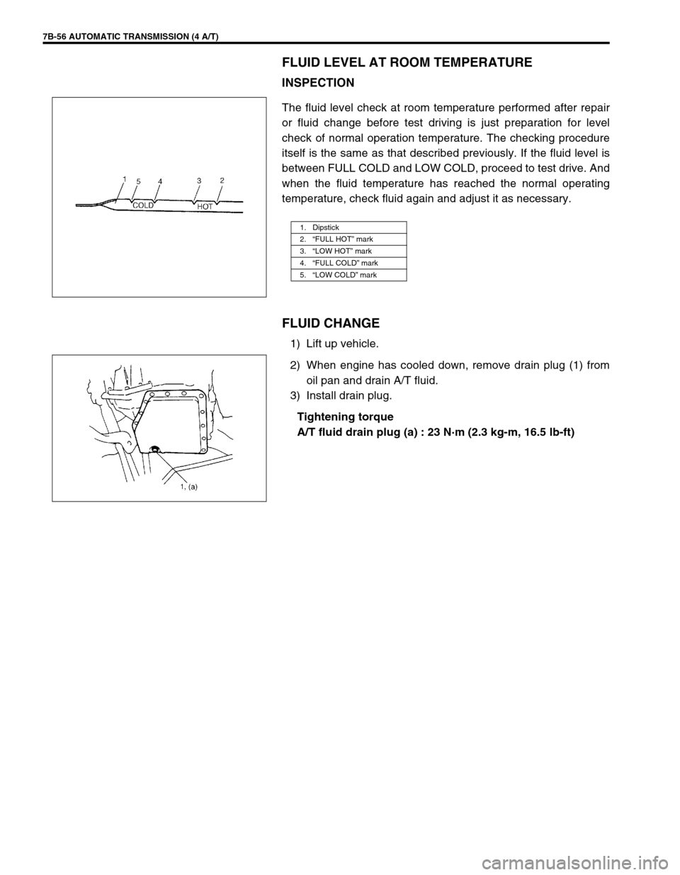
The fluid level check at room temperature performed after repair
or fluid change before test driving is just preparation for level
check of normal operation temperature. The checking procedure
itself is the same as that described previously. If the fluid level is
between FULL COLD and LOW COLD, proceed to test drive. And
when the fluid temperature has reached the normal operating
temperature, check fluid again and adjust it as necessary.
FLUID CHANGE
1) Lift up vehicle.
2) When engine has cooled down, remove drain plug (1) from
oil pan and drain A/T fluid.
3) Install drain plug.
Tightening torque
A/T fluid drain plug (a) : 23 N·m (2.3 kg-m, 16.5 lb-ft)
1. Dipstick
2.“FULL HOT” mark
3.“LOW HOT” mark
4.“FULL COLD” mark
5.“LOW COLD” mark
Page 99 of 447

AUTOMATIC TRANSMISSION (4 A/T) 7B-57
4) Lower vehicle and fill proper amount of an equivalent of
DEXRON
®-III or DEXRON®-IIE
5) Check fluid level according to procedure described under
“FLUID LEVEL AT NORMAL OPERATING TEMPERA-
TURE.
A/T fluid specification
: An equivalent of DEXRON
®-III or DEXRON®-IIE
A/T fluid capacity
When draining from drain plug hole :
4.0 liters (8.45/7.04 US/Imp. pt.)
When overhauling :
5.1 liters (10.78/8.98 US/Imp. pt.)
SELECTOR LEVER
1. Dipstick
2.“FULL HOT” mark
3.“LOW HOT” mark
4.“FULL COLD” mark
5.“LOW COLD” mark
1
1. Selector lever assembly 4. Selector indicator assembly
2. Selector lever knob assembly 5. Screw
3. Screw 6. Illumination lamp assembly
Page 104 of 447

7B-62 AUTOMATIC TRANSMISSION (4 A/T)
OUTPUT SHAFT SPEED SENSOR (A/T VSS)
INSPECTION
1) Disconnect negative cable at battery.
2) Disconnect output shaft speed sensor – input shaft speed
sensor coupler (1).
3) Check resistance between output shaft speed sensor termi-
nals (2).
Output shaft speed sensor resistance
Standard : 160 – 200
Ω
ΩΩ Ω at 20°C (68°F)
REMOVAL
1) Disconnect negative cable at battery.
2) Disconnect output shaft speed sensor – input shaft speed
sensor coupler.
3) Remove output shaft speed sensor (1) by removing its bolt.
INSTALLATION
1) Apply A/T fluid to output shaft speed sensor o-ring.
2) Install output shaft speed sensor (1) to A/T case and tighten
bolt to specified torque.
Tightening torque
Output shaft speed sensor bolt
(a) : 8 N·m (0.8 kg-m, 6.0 lb-ft)
3) Connect output shaft speed sensor – input shaft speed sen-
sor coupler.
4) Connect negative cable to battery.
Page 105 of 447

AUTOMATIC TRANSMISSION (4 A/T) 7B-63
INPUT SHAFT SPEED SENSOR
INSPECTION
1) Disconnect negative cable at battery.
2) Disconnect output shaft speed sensor – input shaft speed
sensor coupler (1).
3) Check resistance between input shaft speed sensor termi-
nals (2).
Input shaft speed sensor resistance
Standard : 160 – 200
Ω
ΩΩ Ω at 20°C (68°F)
REMOVAL
1) Disconnect negative cable at battery.
2) Disconnect output shaft speed sensor – input shaft speed
sensor coupler.
3) Remove input shaft speed sensor (1) by removing its bolt.
INSTALLATION
1) Apply A/T fluid to input shaft speed sensor O-ring.
2) Install input shaft speed sensor (1) to A/T case and tighten
bolt to specified torque.
Tightening torque
Input shaft speed sensor bolt
(b) : 8 N·m (0.8 kg-m, 6.0 lb-ft)
3) Connect output shaft speed sensor – input shaft speed sen-
sor coupler.
4) Connect negative cable to battery.
VEHICLE SPEED SENSOR (VSS)
Refer to Section 6E for removal, installation and inspection.
THROTTLE POSITION SENSOR
INSPECTION
Check throttle position sensor referring to Section 6E.
Page 107 of 447

AUTOMATIC TRANSMISSION (4 A/T) 7B-65
O/D OFF SWITCH
INSPECTION
1) Remove console box.
2) Disconnect O/D off switch coupler (1).
3) Check continuity between O/D off switch terminals.
O/D OFF switch specification
SHIFT SOLENOID VALVES AND TRANSMIS-
SION TEMPERATURE SENSOR
REMOVAL
1) Disconnect negative cable at battery.
2) Drain A/T fluid.
3) Remove A/T oil pan (1).
4) Disconnect transmission temp. sensor coupler (3).
5) Remove A/T oil strainer (2) and transmission temp. sensor
(1). O/D off switch ON OFF
Continuity Continuity No continuity
2. O/D off switch ON
3. O/D off switch OFF
Page 109 of 447
AUTOMATIC TRANSMISSION (4 A/T) 7B-67
INSTALLATION
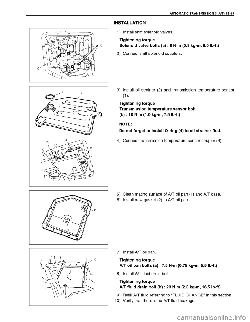
1) Install shift solenoid valves.
Tightening torque
Solenoid valve bolts (a) : 8 N·m (0.8 kg-m, 6.0 lb-ft)
2) Connect shift solenoid couplers.
3) Install oil strainer (2) and transmission temperature sensor
(1).
Tightening torque
Transmission temperature sensor bolt
(b) : 10 N·m (1.0 kg-m, 7.5 lb-ft)
4) Connect transmission temperature sensor coupler (3).
5) Clean mating surface of A/T oil pan (1) and A/T case.
6) Install new gasket (2) to A/T oil pan.
7) Install A/T oil pan.
Tightening torque
A/T oil pan bolts (a) : 7.5 N·m (0.75 kg-m, 5.5 lb-ft)
8) Install A/T fluid drain bolt.
Tightening torque
A/T fluid drain bolt (b) : 23 N·m (2.3 kg-m, 16.5 lb-ft)
9) Refill A/T fluid referring to “FLUID CHANGE” in this section.
10) Verify that there is no A/T fluid leakage.
NOTE:
Do not forget to install O-ring (4) to oil strainer first.