automatic transmission SUZUKI SWIFT 2000 1.G Transmission Service Owner's Guide
[x] Cancel search | Manufacturer: SUZUKI, Model Year: 2000, Model line: SWIFT, Model: SUZUKI SWIFT 2000 1.GPages: 447, PDF Size: 10.54 MB
Page 73 of 447
AUTOMATIC TRANSMISSION (4 A/T) 7B-31
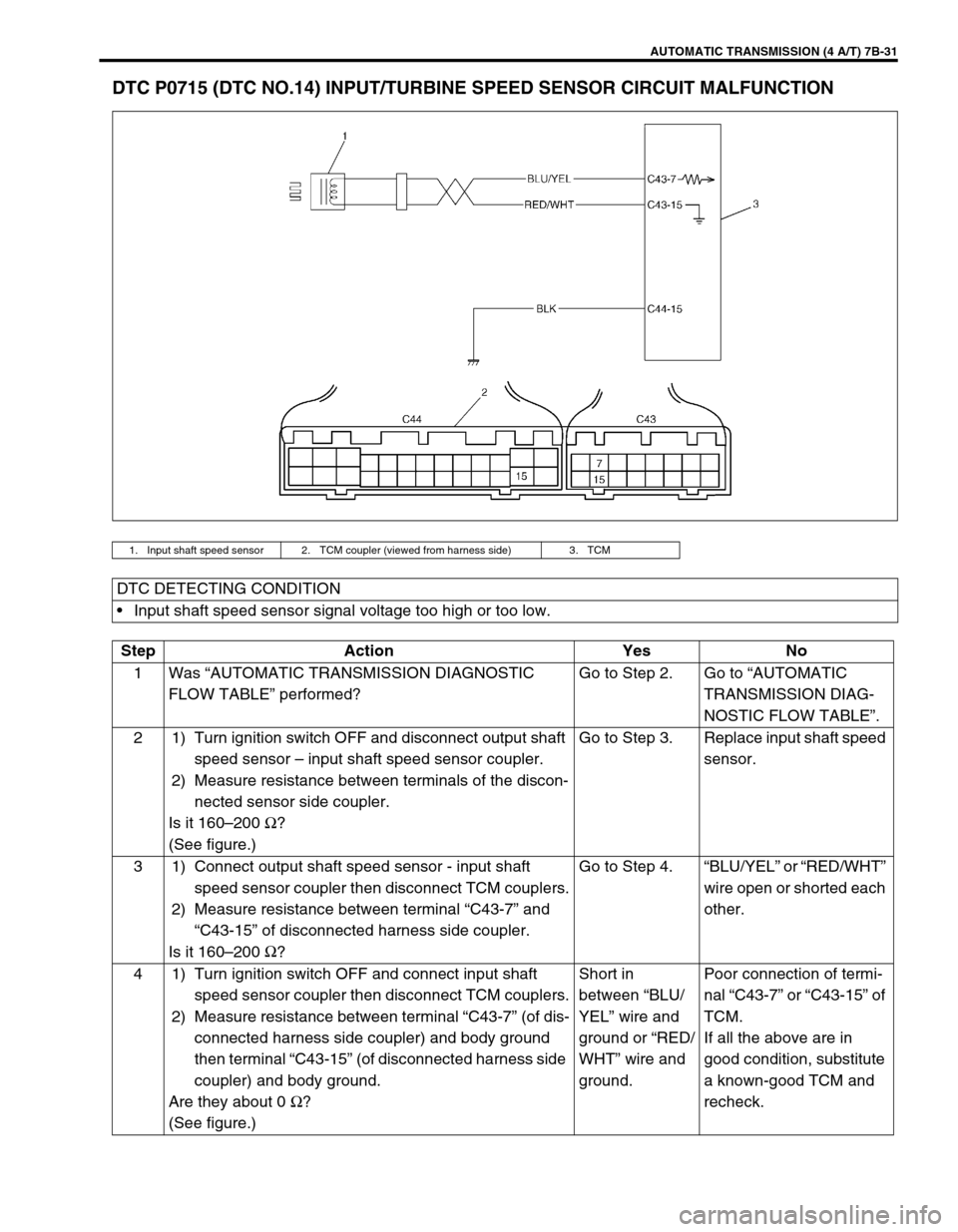
DTC P0715 (DTC NO.14) INPUT/TURBINE SPEED SENSOR CIRCUIT MALFUNCTION
1. Input shaft speed sensor 2. TCM coupler (viewed from harness side) 3. TCM
DTC DETECTING CONDITION
Input shaft speed sensor signal voltage too high or too low.
Step Action Yes No
1Was “AUTOMATIC TRANSMISSION DIAGNOSTIC
FLOW TABLE” performed?Go to Step 2. Go to “AUTOMATIC
TRANSMISSION DIAG-
NOSTIC FLOW TABLE”.
2 1) Turn ignition switch OFF and disconnect output shaft
speed sensor – input shaft speed sensor coupler.
2) Measure resistance between terminals of the discon-
nected sensor side coupler.
Is it 160–200 Ω
?
(See figure.)Go to Step 3. Replace input shaft speed
sensor.
3 1) Connect output shaft speed sensor - input shaft
speed sensor coupler then disconnect TCM couplers.
2) Measure resistance between terminal “C43-7” and
“C43-15” of disconnected harness side coupler.
Is it 160–200 Ω
?Go to Step 4.“BLU/YEL” or “RED/WHT”
wire open or shorted each
other.
4 1) Turn ignition switch OFF and connect input shaft
speed sensor coupler then disconnect TCM couplers.
2) Measure resistance between terminal “C43-7” (of dis-
connected harness side coupler) and body ground
then terminal “C43-15” (of disconnected harness side
coupler) and body ground.
Are they about 0 Ω
?
(See figure.)Short in
between “BLU/
YEL” wire and
ground or “RED/
WHT” wire and
ground.Poor connection of termi-
nal “C43-7” or “C43-15” of
TCM.
If all the above are in
good condition, substitute
a known-good TCM and
recheck.
Page 74 of 447

7B-32 AUTOMATIC TRANSMISSION (4 A/T)
Figure for Step 2
Figure for Step 4
1. Output shaft speed sensor - Input shaft speed sensor coupler
2. Input shaft speed sensor terminal
Page 75 of 447
AUTOMATIC TRANSMISSION (4 A/T) 7B-33
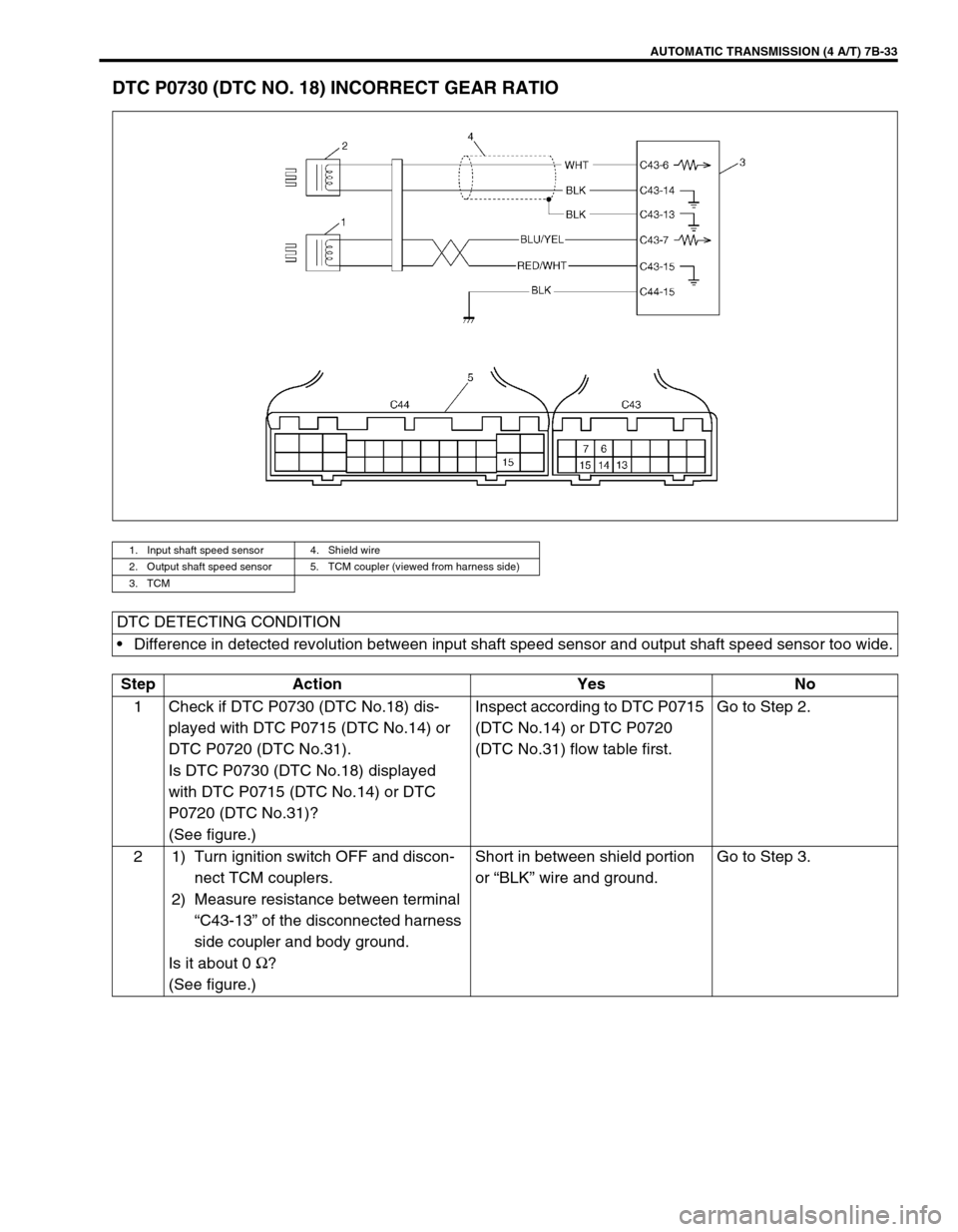
DTC P0730 (DTC NO. 18) INCORRECT GEAR RATIO
1. Input shaft speed sensor 4. Shield wire
2. Output shaft speed sensor 5. TCM coupler (viewed from harness side)
3. TCM
DTC DETECTING CONDITION
Difference in detected revolution between input shaft speed sensor and output shaft speed sensor too wide.
Step Action Yes No
1 Check if DTC P0730 (DTC No.18) dis-
played with DTC P0715 (DTC No.14) or
DTC P0720 (DTC No.31).
Is DTC P0730 (DTC No.18) displayed
with DTC P0715 (DTC No.14) or DTC
P0720 (DTC No.31)?
(See figure.)Inspect according to DTC P0715
(DTC No.14) or DTC P0720
(DTC No.31) flow table first.Go to Step 2.
2 1) Turn ignition switch OFF and discon-
nect TCM couplers.
2) Measure resistance between terminal
“C43-13” of the disconnected harness
side coupler and body ground.
Is it about 0 Ω
?
(See figure.)Short in between shield portion
or “BLK” wire and ground.Go to Step 3.
Page 76 of 447
7B-34 AUTOMATIC TRANSMISSION (4 A/T)
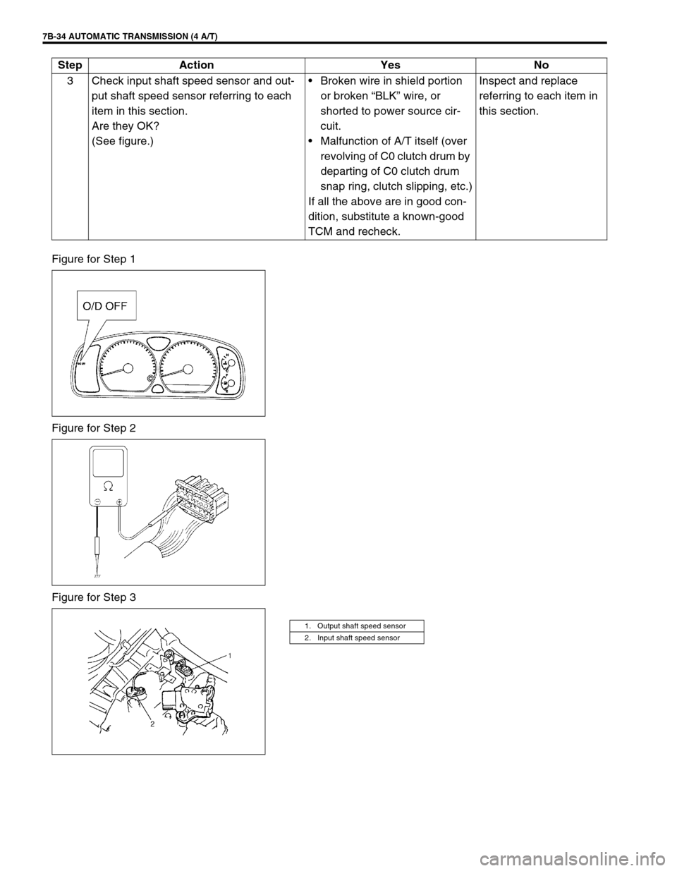
Figure for Step 1
Figure for Step 2
Figure for Step 33 Check input shaft speed sensor and out-
put shaft speed sensor referring to each
item in this section.
Are they OK?
(See figure.)Broken wire in shield portion
or broken “BLK” wire, or
shorted to power source cir-
cuit.
Malfunction of A/T itself (over
revolving of C0 clutch drum by
departing of C0 clutch drum
snap ring, clutch slipping, etc.)
If all the above are in good con-
dition, substitute a known-good
TCM and recheck.Inspect and replace
referring to each item in
this section. Step Action Yes No
1. Output shaft speed sensor
2. Input shaft speed sensor
Page 77 of 447
AUTOMATIC TRANSMISSION (4 A/T) 7B-35
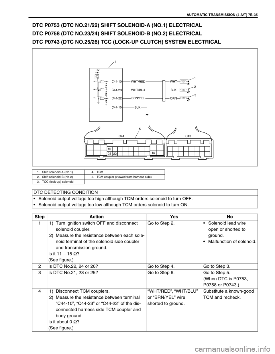
DTC P0753 (DTC NO.21/22) SHIFT SOLENOID-A (NO.1) ELECTRICAL
DTC P0758 (DTC NO.23/24) SHIFT SOLENOID-B (NO.2) ELECTRICAL
DTC P0743 (DTC NO.25/26) TCC (LOCK-UP CLUTCH) SYSTEM ELECTRICAL
1. Shift solenoid-A (No.1) 4. TCM
2. Shift solenoid-B (No.2) 5. TCM coupler (viewed from harness side)
3. TCC (lock-up) solenoid
DTC DETECTING CONDITION
Solenoid output voltage too high although TCM orders solenoid to turn OFF.
Solenoid output voltage too low although TCM orders solenoid to turn ON.
Step Action Yes No
1 1) Turn ignition switch OFF and disconnect
solenoid coupler.
2) Measure the resistance between each sole-
noid terminal of the solenoid side coupler
and transmission ground.
Is it 11 – 15 Ω
?
(See figure.)Go to Step 2.Solenoid lead wire
open or shorted to
ground.
Malfunction of solenoid.
2 Is DTC No.22, 24 or 26? Go to Step 4. Go to Step 3.
3 Is DTC No.21, 23 or 25? Go to Step 6. Go to Step 5.
(When DTC is P0753,
P0758 or P0743.)
4 1) Disconnect TCM couplers.
2) Measure the resistance between terminal
“C44-10”, “C44-23” or “C44-22” of the dis-
connected harness side TCM coupler and
body ground.
Is it about 0 Ω
?
(See figure.)“WHT/RED”, “WHT/BLU”
or “BRN/YEL” wire
shorted to ground.Substitute a known-good
TCM and recheck.
Page 78 of 447

7B-36 AUTOMATIC TRANSMISSION (4 A/T)
Figure for Step 1
Figure for Step 4, 5, 6, 75 1) Disconnect TCM couplers.
2) Measure the resistance between terminal
“C44-10”, “C44-23” or “C44-22” of the dis-
connected harness side TCM coupler and
body ground.
Is it about 0 Ω
?
(See figure.)“WHT/RED”, “WHT/BLU”,
or “BRN/YEL” wire
shorted to ground.Go to Step 6.
6 1) Connect solenoid coupler then disconnect
TCM couplers.
2) Measure the resistance between each sole-
noid terminal of the disconnected harness
side TCM coupler and body ground.
Is it 10.5 – 15.5 Ω
?Go to Step 7.“WHT/RED”, “WHT/BLU”
or “BRN/YEL” wire open
or poor connection of shift
solenoid coupler.
7 Turn ignition switch ON then measure voltage
between terminal “C44-10”, “C44-23” or “C44-
22” of the disconnected harness side TCM cou-
pler and body ground.
Is it about 0 V?Poor connection at termi-
nal “C44-10”, “C44-23” or
“C44-22” of TCM.
If all the above are in
good condition, substitute
a known-good TCM and
recheck.“WHT/RED”, “WHT/BLU”
or “BRN/YEL” wire or shift
solenoid lead wire shorted
to power source circuit. Step Action Yes No
Solenoid TCM Terminal NumberLead Wire Color
(between TCM and solenoid coupler)
Shift solenoid -A (No.1) C44-10 WHT/RED
Shift solenoid -B (No.2) C44-23 WHT/BLU
TCC solenoid (Lock-up solenoid) C44-22 BRN/YEL
1. Shift solenoid -A (No.1) terminal
2. Shift solenoid -B (No.2) terminal
3. TCC (Lock-up) solenoid terminal
4. Solenoid coupler
5. Transmission range sensor (Shift switch)
1.“C44-10” terminal
2.“C44-23” terminal
3.“C44-22” terminal
4. TCM couples
Page 79 of 447
AUTOMATIC TRANSMISSION (4 A/T) 7B-37
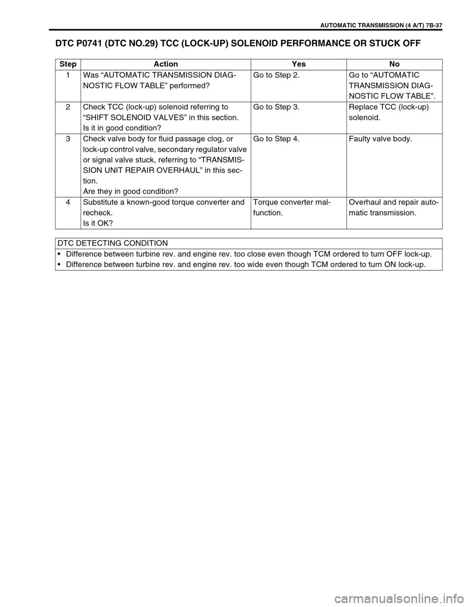
DTC P0741 (DTC NO.29) TCC (LOCK-UP) SOLENOID PERFORMANCE OR STUCK OFF
Step Action Yes No
1Was “AUTOMATIC TRANSMISSION DIAG-
NOSTIC FLOW TABLE” performed?Go to Step 2. Go to “AUTOMATIC
TRANSMISSION DIAG-
NOSTIC FLOW TABLE”.
2 Check TCC (lock-up) solenoid referring to
“SHIFT SOLENOID VALVES” in this section.
Is it in good condition?Go to Step 3. Replace TCC (lock-up)
solenoid.
3 Check valve body for fluid passage clog, or
lock-up control valve, secondary regulator valve
or signal valve stuck, referring to “TRANSMIS-
SION UNIT REPAIR OVERHAUL” in this sec-
tion.
Are they in good condition?Go to Step 4. Faulty valve body.
4 Substitute a known-good torque converter and
recheck.
Is it OK?Torque converter mal-
function.Overhaul and repair auto-
matic transmission.
DTC DETECTING CONDITION
Difference between turbine rev. and engine rev. too close even though TCM ordered to turn OFF lock-up.
Difference between turbine rev. and engine rev. too wide even though TCM ordered to turn ON lock-up.
Page 80 of 447
7B-38 AUTOMATIC TRANSMISSION (4 A/T)
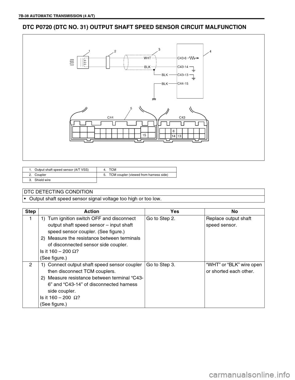
DTC P0720 (DTC NO. 31) OUTPUT SHAFT SPEED SENSOR CIRCUIT MALFUNCTION
1. Output shaft speed sensor (A/T VSS) 4. TCM
2. Coupler 5. TCM coupler (viewed from harness side)
3. Shield wire
DTC DETECTING CONDITION
Output shaft speed sensor signal voltage too high or too low.
Step Action Yes No
1 1) Turn ignition switch OFF and disconnect
output shaft speed sensor – input shaft
speed sensor coupler. (See figure.)
2) Measure the resistance between terminals
of disconnected sensor side coupler.
Is it 160 – 200 Ω
?
(See figure.)Go to Step 2. Replace output shaft
speed sensor.
2 1) Connect output shaft speed sensor coupler
then disconnect TCM couplers.
2) Measure resistance between terminal “C43-
6” and “C43-14” of disconnected harness
side coupler.
Is it 160 – 200 Ω
?
(See figure.)Go to Step 3.“WHT” or “BLK” wire open
or shorted each other.
Page 81 of 447

AUTOMATIC TRANSMISSION (4 A/T) 7B-39
Figure for Step 1, 2
Figure for Step 2, 33 1) Turn ignition switch OFF and disconnect
output shaft speed sensor – input shaft
speed sensor coupler. (See figure.)
2) Measure resistance between terminal “3”
(of disconnected sensor side coupler) and
body ground then terminal “4” (of discon-
nected sensor side coupler) and body
ground.
Is it about 0 Ω
?
(See figure.)Replace output shaft
speed sensor.Go to Step 4.
4 1) Turn ignition switch OFF and connect out-
put shaft speed sensor coupler then discon-
nect TCM couplers.
2) Measure resistance between terminal “C43-
6” (of disconnected harness side coupler)
and body ground then terminal “C43-14” (of
disconnected harness side coupler) and
body ground.
Is it about 0 Ω
?
(See figure.)“WHT” or “BLK” wire
shorted to ground.Go to Step 5.
5 Measure resistance between terminal “C43-6”
and “C43-13” (of disconnected harness side
coupler) then terminal “C43-14” and “C43-13”
(of disconnected harness side coupler).
Is it about 0 Ω
?
(See figure.)“WHT” wire or “BLK” wire
shorted to shield portion.Poor connection of termi-
nal “C43-6” or “C43-14” of
the TCM.
If all the above are in
good condition, substitute
a known-good TCM and
recheck. Step Action Yes No
1. Output shaft speed sensor
2. Input shaft speed sensor coupler
1. Terminal “3”
2. Terminal “4”
Page 82 of 447

7B-40 AUTOMATIC TRANSMISSION (4 A/T)
Figure for Step 2, 5
Figure for Step 4
1.“C43-14” terminal
2.“C43-6” terminal
3.“C43-13” terminal
4. TCM coupler
1.“C43-14” terminal
2.“C43-6” terminal
3. TCM coupler