fuse diagram SUZUKI SWIFT 2000 1.G Transmission Service Workshop Manual
[x] Cancel search | Manufacturer: SUZUKI, Model Year: 2000, Model line: SWIFT, Model: SUZUKI SWIFT 2000 1.GPages: 447, PDF Size: 10.54 MB
Page 288 of 447

8G-10 IMMOBILIZER CONTROL SYSTEM
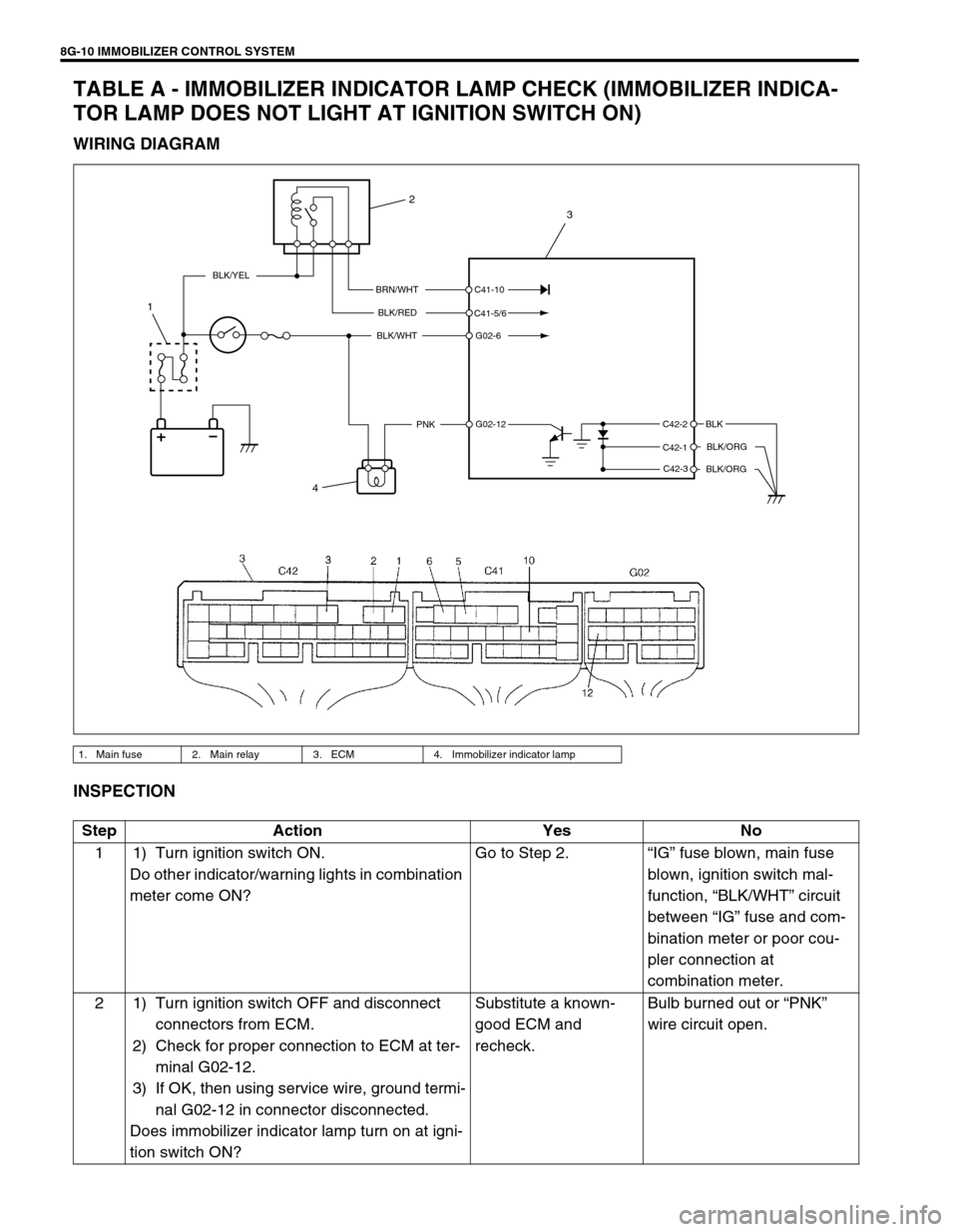
TABLE A - IMMOBILIZER INDICATOR LAMP CHECK (IMMOBILIZER INDICA-
TOR LAMP DOES NOT LIGHT AT IGNITION SWITCH ON)
WIRING DIAGRAM
INSPECTION
1. Main fuse 2. Main relay 3. ECM 4. Immobilizer indicator lamp
BRN/WHT
BLK/RED
BLK/WHT
PNKBLK
BLK/ORG
BLK/ORG
BLK/YEL
C42-2
C42-1
C42-3 C41-10
C41-5/6
G02-6
G02-12
4
1
2
3
Step Action Yes No
1 1) Turn ignition switch ON.
Do other indicator/warning lights in combination
meter come ON?Go to Step 2.“IG” fuse blown, main fuse
blown, ignition switch mal-
function, “BLK/WHT” circuit
between “IG” fuse and com-
bination meter or poor cou-
pler connection at
combination meter.
2 1) Turn ignition switch OFF and disconnect
connectors from ECM.
2) Check for proper connection to ECM at ter-
minal G02-12.
3) If OK, then using service wire, ground termi-
nal G02-12 in connector disconnected.
Does immobilizer indicator lamp turn on at igni-
tion switch ON?Substitute a known-
good ECM and
recheck.Bulb burned out or “PNK”
wire circuit open.
Page 289 of 447

IMMOBILIZER CONTROL SYSTEM 8G-11
TABLE B - IMMOBILIZER INDICATOR LAMP CHECK (IMMOBILIZER INDICA-
TOR LAMP REMAINS ON AFTER ENGINE STARTS)
WIRING DIAGRAM
INSPECTION
1. Main fuse 2. Main relay 3. ECM 4. Immobilizer indicator lamp
BRN/WHT
BLK/RED
BLK/WHT
PNKBLK
BLK/ORG
BLK/ORG
BLK/YEL
C42-2
C42-1
C42-3 C41-10
C41-5/6
G02-6
G02-12
4
1
2
3
Step Action Yes No
1 1) With ignition switch OFF, disconnect cou-
plers from ECM.
Does immobilizer indicator lamp turn ON at
ignition switch ON?“PNK” wire shorted to
ground circuit.Substitute a known-good
ECM and recheck.
Page 379 of 447

AIR BAG SYSTEM 10B-5
SYSTEM WIRING DIAGRAM
TERMINAL ARRANGEMENT OF SDM (VIEWED FROM HARNESS SIDE)
1
2
3
4 BLK/YEL
BLK/YELBLK/WHT
YEL/BLK
YEL/BLKGRN/RED
GRN GRNWHT WHT
GRN
BLU/RED
YEL/RED
GRN/ORN
GRN/YEL
BLU/ORN
BLU/YEL
6
12V
5V REDRED
BLU
BLU
5
8
7“G39”
“Q02”
“Q07” “Q05”
9
10PPL
BLK
“Q04”
Q06-2
Q06-4
Q06-14Q06-7
Q06-8 Q06-10
Q06-9
Q06-12
Q06-11
Q06-5
Q06-6 Q06-15
Q06-17L1
L2
IG
SDL
DNS
GNDLA
PP- PP+ DP- DP+P- P+ D- D+
“Q03”
“Q01”
“Q06”
“Q08”
15
161413
12 11
[A]
[B]
[C]
“Q01” “Q08”, “G39”
“Q06”
[A]: Shorting bar 5.“AIR BAG” fuse 12. Contact coil assembly
[B]: Air bag harness 6. Connection detection pin 13. Driver air bag (inflator) module
[C]: Connector 7. To ECM, TCM (if equipped) and ABS control
module (if equipped) 14. Passenger air bag (inflator) module
1. From main fuse 8. To data link connector (DLC) 15. Driver seat belt pretensioner (if equipped)
2. Ignition switch 9.“AIR BAG” monitor coupler 16. Passenger seat belt pretensioner (if equipped)
3.“IG METER” fuse 10. Ground for air bag system
4.“AIR BAG” warning lamp in combination meter 11. SDM
1. CONNECTOR “Q06” (SDM CONNECTOR)
Page 389 of 447

AIR BAG SYSTEM 10B-15
TABLE A - “AIR BAG” WARNING LAMP COMES ON STEADY
TABLE B - “AIR BAG” WARNING LAMP DOES NOT COME ON
TABLE C - “AIR BAG” WARNING LAMP FLASHES
TABLE D - “AIR BAG” WARNING LAMP CANNOT INDICATE FLASHING PAT-
TERN OF DTC
WIRING DIAGRAM
1. From main fuse 5.“AIR BAG” fuse 9. To ECM, TCM (if equipped) and ABS control
module (if equipped)
2. Ignition switch 6. Connection detection pin 10.“AIR BAG” monitor coupler
3.“IG·COIL METER” fuse 7. SDM 11. Ground for air bag system
4.“AIR BAG” warning lamp in combination meter 8. To DLC [A]: Air bag harness
1
2
34 BLK/YEL
BLK/YELBLK/WHTYEL/BLKYEL/BLK
6
REDRED
BLU
BLU
5
8
9
10
11
PPL
BLK
“Q04”“Q06”
Q06-2
Q06-4
Q06-14
Q06-15
Q06-17L1
L2
IG
SDL
DNS
GNDLA
7
[A]
12V
5V
“G39”“Q02”
CAUTION:
Be sure to perform AIR BAG DIAGNOSTIC SYSTEM CHECK before starting diagnosis according to
flow table.
When measurement of resistance or voltage is required in this table, use a tester along with a cor-
rect terminal adapter from special tool (Connector test adapter kit).
When a check for proper connection is required, refer to INTERMITTENT AND POOR CONNEC-
TIONS in this section.
If there is open circuit in the air bag wire harness, connector or terminal is found damaged, replace
the wire harness, connector and terminal as an assembly.
Page 395 of 447

AIR BAG SYSTEM 10B-21
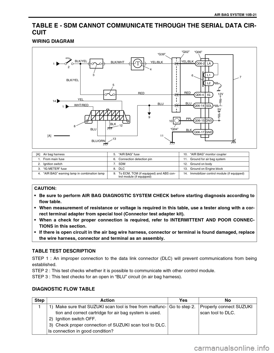
TABLE E - SDM CANNOT COMMUNICATE THROUGH THE SERIAL DATA CIR-
CUIT
WIRING DIAGRAM
TABLE TEST DESCRIPTION
STEP 1 : An improper connection to the data link connector (DLC) will prevent communications from being
established.
STEP 2 : This test checks whether it is possible to communicate with other control module.
STEP 3 : This test checks for an open in “BLU” circuit (in air bag harness).
DIAGNOSTIC FLOW TABLE
[A]: Air bag harness 5.“AIR BAG” fuse 10.“AIR BAG” monitor coupler
1. From main fuse 6. Connection detection pin 11. Ground for air bag system
2. Ignition switch 7. SDM 12. Ground on body
3.“IG METER” fuse 8. DLC 13. Ground on Engine block
4.“AIR BAG” warning lamp in combination lamp 9. To ECM, TCM (if equipped) and ABS con-
trol module (if equipped)14. Immobilizer control module (if equipped)
1
14
12
34 BLK/YEL
BLK/YEL
YELBLK/WHT
BLK
BLU/ORNYEL/BLKYEL/BLK
6
RED
WHT/REDRED
BLU
BLU
BLU
5
9
10
11
PPL
BLK
“Q04”“Q06”
Q06-2
Q06-4
Q06-14
Q06-15
Q06-17L1
L2
IG
SDL
DNS
GNDLA
7
[A]
12V
5V
“G39”“Q02”
812
13
CAUTION:
Be sure to perform AIR BAG DIAGNOSTIC SYSTEM CHECK before starting diagnosis according to
flow table.
When measurement of resistance or voltage is required in this table, use a tester along with a cor-
rect terminal adapter from special tool (Connector test adapter kit).
When a check for proper connection is required, refer to INTERMITTENT AND POOR CONNEC-
TIONS in this section.
If there is open circuit in the air bag wire harness, connector or terminal is found damaged, replace
the wire harness, connector and terminal as an assembly.
Step Action Yes No
1 1) Make sure that SUZUKI scan tool is free from malfunc-
tion and correct cartridge for air bag system is used.
2) Ignition switch OFF.
3) Check proper connection of SUZUKI scan tool to DLC.
Is connection in good condition?Go to step 2. Properly connect SUZUKI
scan tool to DLC.
Page 397 of 447

AIR BAG SYSTEM 10B-23
DTC B1015 - PASSENGER AIR BAG INITIATOR CIRCUIT RESISTANCE HIGH
DTC B1016 - PASSENGER AIR BAG INITIATOR CIRCUIT RESISTANCE LOW
DTC B1018 - PASSENGER AIR BAG INITIATOR CIRCUIT SHORT TO GROUND
DTC B1019 - PASSENGER AIR BAG INITIATOR CIRCUIT SHORT TO POWER
CIRCUIT
WIRING DIAGRAM
DTC WILL SET WHEN
DTC B1015 :
The combined resistance of the passenger air bag (inflator) module, harness wiring and connector terminal con-
tact is above a specified value for specified time.
DTC B1016 :
The combined resistance of the passenger air bag (inflator) module, harness wiring and connector terminal con-
tact is below a specified value for specified time.
DTC B1018 :
The voltage measured at passenger air bag initiator circuit is below a specified value for specified time.
DTC B1019 :
The voltage measured at passenger air bag initiator circuit is above a specified value for specified time.
TABLE TEST DESCRIPTION
DTC B1015, B1016, B1018 and B1019 :
STEP 1 : Check whether malfunction is in passenger air bag (inflator) module.
STEP 2 : Check passenger air bag (inflator) module initiator circuit in air bag harness.
STEP 3 : Check passenger air bag (inflator) module initiator circuit in air bag harness. (for DTC B1019 only)
[A]: Shorting bar 1. From main fuse 3.“AIR BAG” fuse 5. Passenger air bag (inflator) module
[B]: Air bag harness 2. Ignition switch 4. SDM 6. Ground for air bag system
1
2RED BLK/YELRED
3
6
BLK“Q06”
Q06-4
Q06-17IG
GND4
“G39”“Q02”
BLU/RED
YEL/RED Q06-7
Q06-8 P- P+“Q03”
“Q06”
5
[A]
[B]
CAUTION:
Be sure to perform AIR BAG DIAGNOSTIC SYSTEM CHECK before starting diagnosis according to
flow table.
When measurement of resistance or voltage is required in this table, use a tester along with a cor-
rect terminal adaptor from special tool (Connector test adapter kit).
When a check for proper connection is required, refer to INTERMITTENT AND POOR CONNEC-
TIONS in this section.
If there is open circuit in the air bag wire harness, connector or terminal is found damaged, replace
the wire harness, connector and terminal as an assembly.
Page 403 of 447

AIR BAG SYSTEM 10B-29
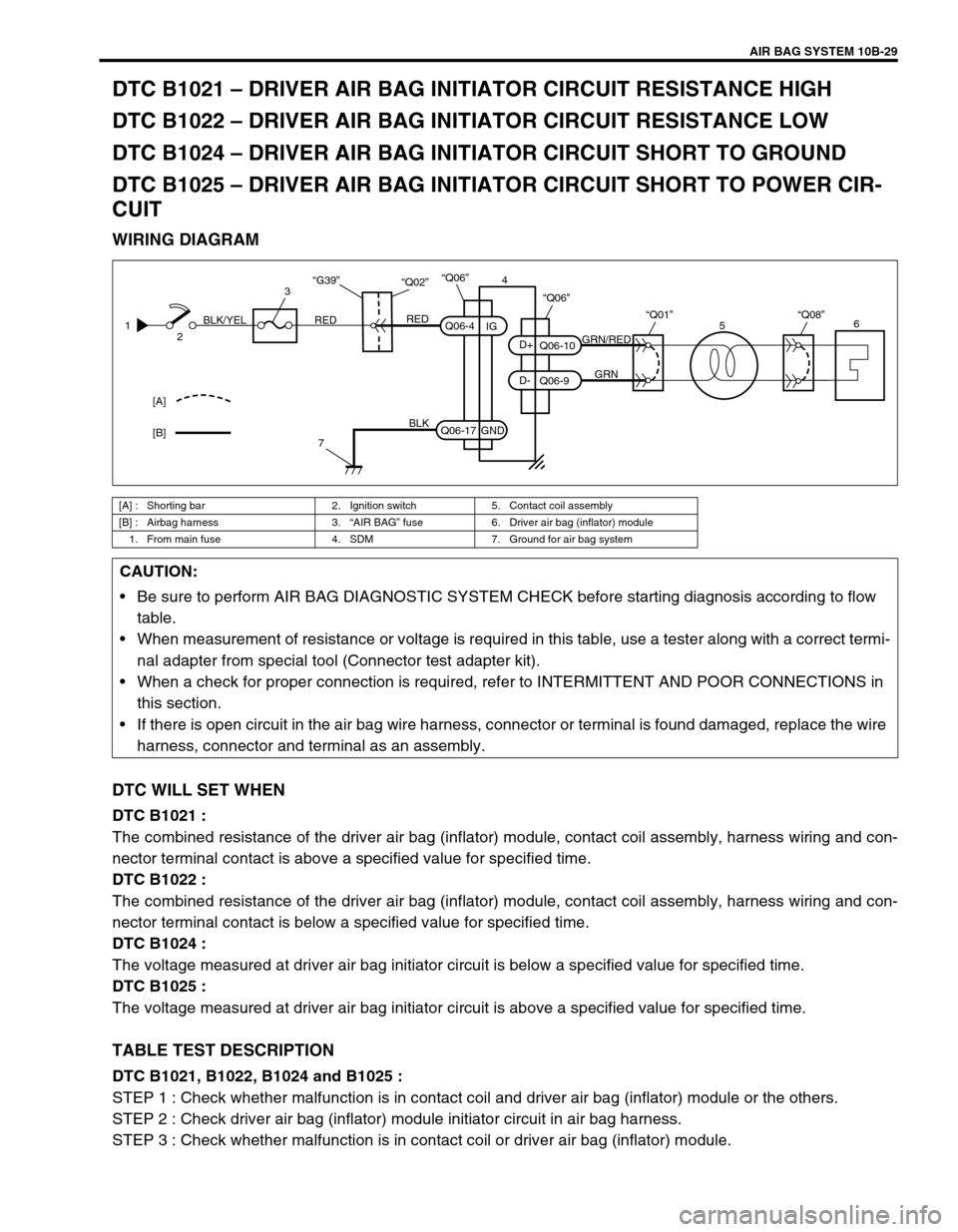
DTC B1021 – DRIVER AIR BAG INITIATOR CIRCUIT RESISTANCE HIGH
DTC B1022 – DRIVER AIR BAG INITIATOR CIRCUIT RESISTANCE LOW
DTC B1024 – DRIVER AIR BAG INITIATOR CIRCUIT SHORT TO GROUND
DTC B1025 – DRIVER AIR BAG INITIATOR CIRCUIT SHORT TO POWER CIR-
CUIT
WIRING DIAGRAM
DTC WILL SET WHEN
DTC B1021 :
The combined resistance of the driver air bag (inflator) module, contact coil assembly, harness wiring and con-
nector terminal contact is above a specified value for specified time.
DTC B1022 :
The combined resistance of the driver air bag (inflator) module, contact coil assembly, harness wiring and con-
nector terminal contact is below a specified value for specified time.
DTC B1024 :
The voltage measured at driver air bag initiator circuit is below a specified value for specified time.
DTC B1025 :
The voltage measured at driver air bag initiator circuit is above a specified value for specified time.
TABLE TEST DESCRIPTION
DTC B1021, B1022, B1024 and B1025 :
STEP 1 : Check whether malfunction is in contact coil and driver air bag (inflator) module or the others.
STEP 2 : Check driver air bag (inflator) module initiator circuit in air bag harness.
STEP 3 : Check whether malfunction is in contact coil or driver air bag (inflator) module.
[A] : Shorting bar 2. Ignition switch 5. Contact coil assembly
[B] : Airbag harness 3.“AIR BAG” fuse 6. Driver air bag (inflator) module
1. From main fuse 4. SDM 7. Ground for air bag system
1
2RED BLK/YELRED
3
7
BLK“Q06”
Q06-4
Q06-17IG
GND4
“G39”“Q02”
[A]
[B]
GRN/RED
GRN Q06-10
Q06-9 D- D+“Q01”
“Q06”
“Q08”6
5
CAUTION:
Be sure to perform AIR BAG DIAGNOSTIC SYSTEM CHECK before starting diagnosis according to flow
table.
When measurement of resistance or voltage is required in this table, use a tester along with a correct termi-
nal adapter from special tool (Connector test adapter kit).
When a check for proper connection is required, refer to INTERMITTENT AND POOR CONNECTIONS in
this section.
If there is open circuit in the air bag wire harness, connector or terminal is found damaged, replace the wire
harness, connector and terminal as an assembly.
Page 410 of 447

10B-36 AIR BAG SYSTEM
DTC B1032 – POWER SOURCE VOLTAGE LOW
WIRING DIAGRAM
DTC WILL SET WHEN
The power source voltage is below an approx. 8 V for specified time.
TABLE TEST DESCRIPTION
STEP 1 : Check if voltage applied to SDM is within normal range.
STEP 2 : Check if DTC 32 still exists.
DIAGNOSTIC FLOW TABLE
[A] : Air bag harness 2. Ignition switch 4. SDM
1. From main fuse 3.“AIR BAG” fuse 5. Ground for air bag system
1
2RED BLK/YELRED
3
5
BLK“Q06”
Q06-4
Q06-17IG
GND4
“G39”“Q02”
[A]
CAUTION:
Be sure to perform AIR BAG DIAGNOSTIC SYSTEM CHECK before starting diagnosis according to
flow table.
When measurement of resistance or voltage is required in this table, use a tester along with a cor-
rect terminal adapter from special tool (Connector test adapter kit).
When a check for proper connection is required, refer to INTERMITTENT AND POOR CONNEC-
TIONS in this section.
If there is open circuit in the air bag wire harness, connector or terminal is found damaged, replace
the wire harness, connector and terminal as an assembly.
Step Action Yes No
1 1) Measure voltage on battery.
Is voltage 11 V or more?Go to step 2. Check Charging System
and repair as necessary.
(Refer to DIAGNOSIS in
Section 6H)
2 1) With ignition switch OFF, disconnect SDM.
2) Check proper connection to SDM at “Q06-4”
terminal.
3) If OK then ignition switch ON, and then
check voltage from “Q06-4” terminal on
SDM connector to body ground.
Is voltage 8 V or more?Go to step 4. Go to step 3.
Page 412 of 447

10B-38 AIR BAG SYSTEM
DTC B1041 – DRIVER PRETENSIONER INITIATOR CIRCUIT RESISTANCE
HIGH
DTC B1042 – DRIVER PRETENSIONER INITIATOR CIRCUIT RESISTANCE
LOW
DTC B1043 – DRIVER PRETENSIONER INITIATOR CIRCUIT SHORT TO
GROUND
DTC B1044 – DRIVER PRETENSIONER INITIATOR CIRCUIT SHORT TO
POWER CIRCUIT
DTC B1045 – PASSENGER PRETENSIONER INITIATOR CIRCUIT RESIS-
TANCE HIGH
DTC B1046 – PASSENGER PRETENSIONER INITIATOR CIRCUIT RESIS-
TANCE LOW
DTC B1047 – PASSENGER PRETENSIONER INITIATOR CIRCUIT SHORT TO
GROUND
DTC B1048 – PASSENGER PRETENSIONER INITIATOR CIRCUIT SHORT TO
POWER CIRCUIT
WIRING DIAGRAM
[A] : Shorting bar 2. Ignition switch 5. Driver seat belt pretensioner
[B] : Air bag harness 3.“AIR BAG” fuse 6. Passenger seat belt pretensioner
1. From main fuse 4. SDM 7. Ground for air bag system
GRN/ORN
GRN/YEL
BLU/ORN
BLU/YEL
“Q07” “Q05”
Q06-12
Q06-11
Q06-5
Q06-6 PP- PP+ DP- DP+
“Q06”
5
6 [A]
[B]1
2RED BLK/YELRED
3
7
BLK“Q06”
Q06-4
Q06-17IG
GND4
“G39”“Q02”
CAUTION:
Be sure to perform AIR BAG DIAGNOSTIC SYSTEM CHECK before starting diagnosis according to
flow table.
When measurement of resistance or voltage is required in this table, use a tester along with a cor-
rect terminal adapter from special tool (Connector test adapter kit).
When a check for proper connection is required, refer to INTERMITTENT AND POOR CONNEC-
TIONS in this section.
If there is open circuit in the air bag wire harness, connector or terminal is found damaged, replace
the wire harness, connector and terminal as an assembly.