front suspension SUZUKI SWIFT 2005 2.G Service Workshop Manual
[x] Cancel search | Manufacturer: SUZUKI, Model Year: 2005, Model line: SWIFT, Model: SUZUKI SWIFT 2005 2.GPages: 1496, PDF Size: 34.44 MB
Page 4 of 1496

Downloaded from www.Manualslib.com manuals search engine 00
0
1
2
3
4
5
6
7
8
9
10
11
Vo l u m e 1
Precautions............................................................... 00-iPrecautions ............................................................ 00-1
General Information ................ ................................... 0-i
General Information ............................................... 0A-1
Maintenance and Lubricatio n ................................. 0B-1
Engine ......................................................................... 1-i Precautions .............................................................. 1-1
Engine General Information and Diagnosis ........... 1A-1
Aux. Emission Control Devices .............................. 1B-1
Engine Electrical Devices....................................... 1C-1
Engine Mechanical ................................................. 1D-1
Engine Lubrication System .................................... 1E-1
Engine Cooling System .......................................... 1F-1
Fuel System ...........................................................1G-1
Ignition System....................................................... 1H-1
Starting System ....................................................... 1I-1
Charging System.....................................................1J-1
Exhaust System ..................................................... 1K-1
Suspension ................................................................. 2-i Precautions .............................................................. 2-1
Suspension General Diagnosis .............................. 2A-1
Front Suspension ................................................... 2B-1
Rear Suspension................ .................................... 2C-1
Wheels and Tires ................................................... 2D-1
Driveline / Axle ........................................................... 3-i Precautions .............................................................. 3-1
Drive Shaft / Axle ................................................... 3A-1
Brakes ......................................................................... 4-i Precautions .............................................................. 4-1
Brake Control System and Diagnosis .................... 4A-1
Front Brakes........................................................... 4B-1
Rear Brakes ........................................................... 4C-1
Parking Brake......................................................... 4D-1
ABS ........................................................................ 4E-1
Electronic Stability Program ................................... 4F-1
Vo l u m e 2
Precautions ............................................................... 00-iPrecautions ............................................................ 00-1
Transmission / Transaxle .... ...................................... 5-i
Precautions .............................................................. 5-1
Automatic Transmission/Transaxle ........................ 5A-1
Manual Transmission/Transaxle ............................ 5B-1
Clutch .....................................................................5C-1
Steering ....................................................................... 6-i Precautions .............................................................. 6-1
Steering General Diagnosis ................................... 6A-1
Steering Wheel and Column .................................. 6B-1
Power Assisted Steering System ...........................6C-1
HVAC ........................................................................... 7-i Precautions .............................................................. 7-1
Heater and Ventilation............................................ 7A-1
Air Conditioning System ......................................... 7B-1
Restraint ...................................................................... 8-i Precautions .............................................................. 8-1
Seat Belts ............................................................... 8A-1
Air Bag System ...................................................... 8B-1
Body, Cab and Accessories .... .................................. 9-i
Precautions .............................................................. 9-1
Wiring Systems ...................................................... 9A-1
Lighting Systems .................................................... 9B-1
Instrumentation / Driver Info. / Horn .......................9C-1
Wipers / Washers ...................................................9D-1
Glass / Windows / Mirrors ...................................... 9E-1
Security and Locks ................................................. 9F-1
Seats ..................................................................... 9G-1
Interior Trim ............................................................9H-1
Hood / Fenders / Doors .......................................... 9J-1
Body Structure ....................................................... 9K-1
Paint / Coatings ...................................................... 9L-1
Exterior Trim .......................................................... 9M-1
Control Systems ....................................................... 10-i Precautions ............................................................ 10-1
Body Electrical Control Sy stem ............................ 10B-1
Immobilizer Control System .................................10C-1
Keyless Start System ........................................... 10E-1
TABLE OF CONTENTS
Page 27 of 1496
Downloaded from www.Manualslib.com manuals search engine General Information: 0A-6
When Using Floor Jack
WARNING!
If the vehicle to be jacked up only at the front
or rear end, be sure to block the wheels on
ground in order to ensure safety.
After the vehicle is jacked up, be sure to
support it on stands. It is extremely
dangerous to do any work on the vehicle
raised on jack alone.
CAUTION!
• Never apply jack against rear suspension parts (i.e., stabilizer, etc.) or vehicle floor,
or it may get deformed.
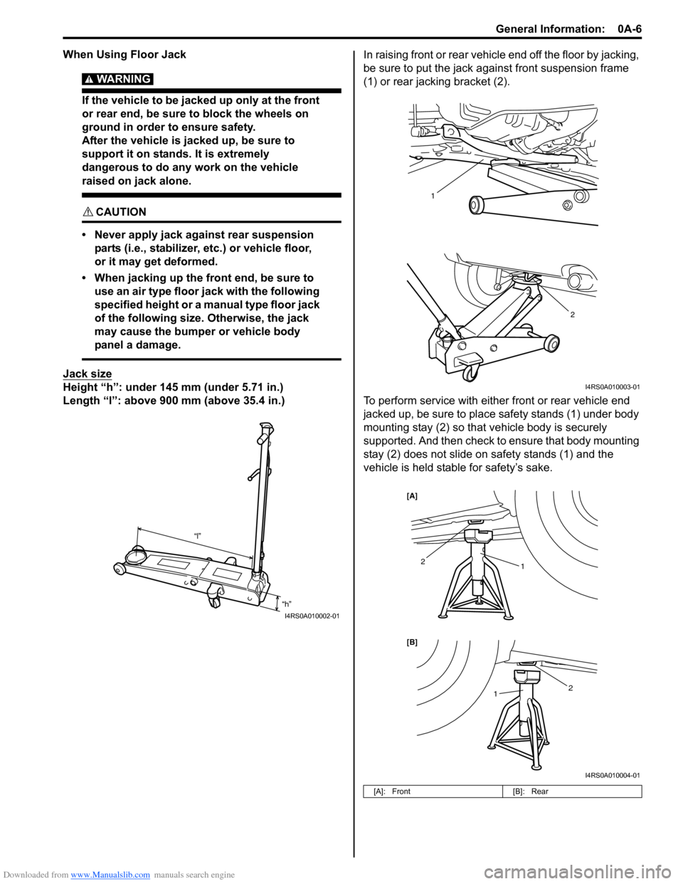
• When jacking up the front end, be sure to use an air type floor jack with the following
specified height or a manual type floor jack
of the following size. Otherwise, the jack
may cause the bumper or vehicle body
panel a damage.
Jack size
Height “h”: under 145 mm (under 5.71 in.)
Length “l”: above 900 mm (above 35.4 in.) In raising front or rear vehicl
e end off the floor by jacking,
be sure to put the jack a gainst front suspension frame
(1) or rear jacking bracket (2).
To perform service with either front or rear vehicle end
jacked up, be sure to place safety stands (1) under body
mounting stay (2) so that vehicle body is securely
supported. And then check to ensure that body mounting
stay (2) does not slide on safety stands (1) and the
vehicle is held stable for safety’s sake.
“h”
“l”
I4RS0A010002-01
[A]: Front
[B]: Rear
2
1
I4RS0A010003-01
1
1
2
2
[B] [A]
I4RS0A010004-01
Page 39 of 1496
Downloaded from www.Manualslib.com manuals search engine Maintenance and Lubrication: 0B-9
Tires InspectionS7RS0B0206020
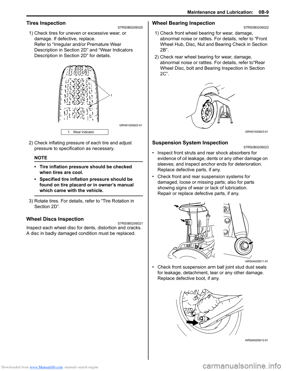
1) Check tires for uneven or excessive wear, or damage. If defective, replace.
Refer to “Irregular and/or Premature Wear
Description in Section 2D” and “Wear Indicators
Description in Section 2D” for details.
2) Check inflating pressure of each tire and adjust pressure to specification as necessary.
NOTE
• Tire inflation pressure should be checked when tires are cool.
• Specified tire inflation pressure should be found on tire placard or in owner’s manual
which came with the vehicle.
3) Rotate tires. For details, refer to “Tire Rotation in Section 2D”.
Wheel Discs InspectionS7RS0B0206021
Inspect each wheel disc for de nts, distortion and cracks.
A disc in badly damaged condition must be replaced.
Wheel Bearing InspectionS7RS0B0206022
1) Check front wheel bearing for wear, damage, abnormal noise or rattles. For details, refer to “Front
Wheel Hub, Disc, Nut and Bearing Check in Section
2B”.
2) Check rear wheel bearing for wear, damage, abnormal noise or rattles. For details, refer to“Rear
Wheel Disc, bolt and Bearing Inspection in Section
2C”.
Suspension System InspectionS7RS0B0206023
• Inspect front struts and rear shock absorbers for evidence of oil leakage, dents or any other damage on
sleeves; and inspect anchor ends for deterioration.
Replace defective parts, if any.
• Check front and rear suspension systems for damaged, loose or missing parts; also for parts
showing signs of wear or lack of lubrication.
Repair or replace defective parts, if any.
• Check front suspension arm ball joint stud dust seals for leakage, detachment, tear or any other damage.
Replace defective boot, if any.
1. Wear indicator
I2RH01020022-01
I2RH01020023-01
I4RS0A020011-01
I4RS0A020012-01
Page 303 of 1496
Downloaded from www.Manualslib.com manuals search engine Engine Mechanical: 1D-18
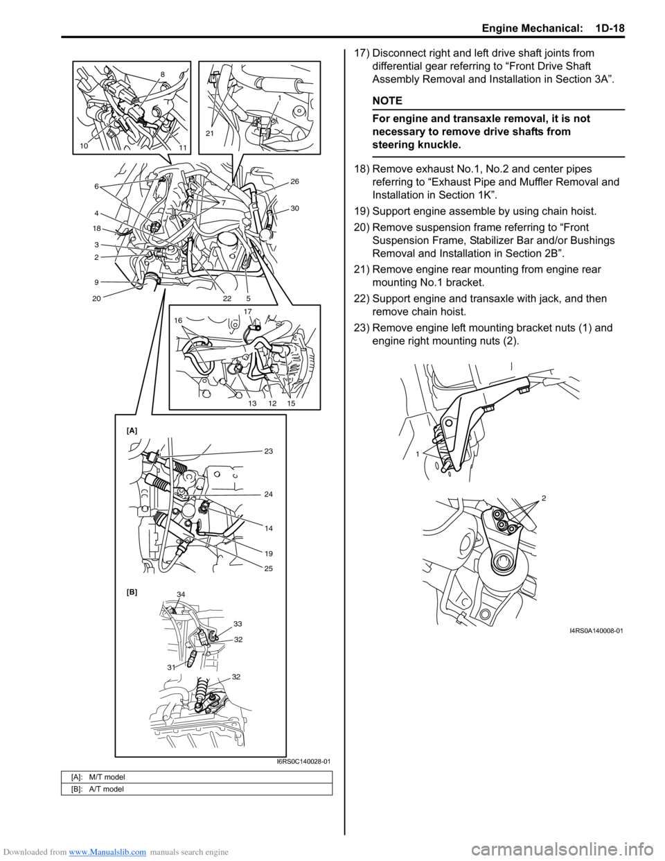
17) Disconnect right and left drive shaft joints from differential gear referring to “Front Drive Shaft
Assembly Removal and Installation in Section 3A”.
NOTE
For engine and transaxle removal, it is not
necessary to remove drive shafts from
steering knuckle.
18) Remove exhaust No.1, No.2 and center pipes referring to “Exhaust Pipe and Muffler Removal and
Installation in Section 1K”.
19) Support engine assemble by using chain hoist.
20) Remove suspension frame referring to “Front Suspension Frame, Stabiliz er Bar and/or Bushings
Removal and Installati on in Section 2B”.
21) Remove engine rear mounting from engine rear mounting No.1 bracket.
22) Support engine and transaxle with jack, and then remove chain hoist.
23) Remove engine left mounting bracket nuts (1) and engine right mounting nuts (2).
[A]: M/T model
[B]: A/T model
7
26
30
5
4
22
3
2
20
6
9
18
8
11
10
21 1
16
17
151213
[B]
23
24
14
25 19
34
33
32
32
31
[A]
I6RS0C140028-01
1
2
I4RS0A140008-01
Page 304 of 1496
Downloaded from www.Manualslib.com manuals search engine 1D-19 Engine Mechanical:
24) Before removing engine with transaxle from engine compartment, recheck to make sure all hoses,
electric wires and cables are disconnected from
engine and transaxle.
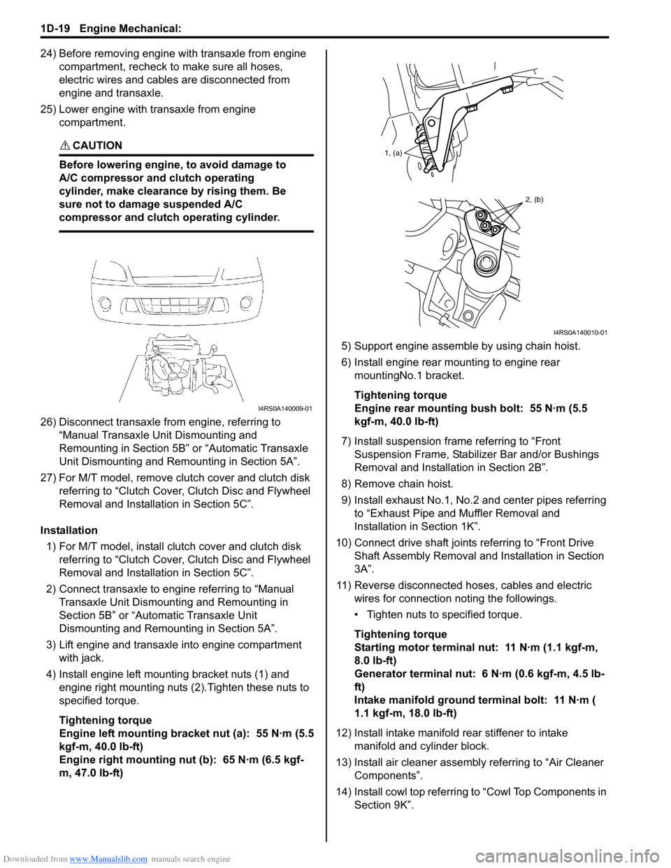
25) Lower engine with transaxle from engine compartment.
CAUTION!
Before lowering engine, to avoid damage to
A/C compressor and clutch operating
cylinder, make clearance by rising them. Be
sure not to damage suspended A/C
compressor and clutch operating cylinder.
26) Disconnect transaxle from engine, referring to “Manual Transaxle Unit Dismounting and
Remounting in Section 5B” or “Automatic Transaxle
Unit Dismounting and Re mounting in Section 5A”.
27) For M/T model, remove clutch cover and clutch disk referring to “Clutch Cover, Clutch Disc and Flywheel
Removal and Installa tion in Section 5C”.
Installation 1) For M/T model, install clutch cover and clutch disk referring to “Clutch Cover, Clutch Disc and Flywheel
Removal and Installa tion in Section 5C”.
2) Connect transaxle to engine referring to “Manual Transaxle Unit Dismounting and Remounting in
Section 5B” or “Automatic Transaxle Unit
Dismounting and Remounting in Section 5A”.
3) Lift engine and transaxle into engine compartment with jack.
4) Install engine left mounting bracket nuts (1) and engine right mounting nuts (2).Tighten these nuts to
specified torque.
Tightening torque
Engine left mounting bracket nut (a): 55 N·m (5.5
kgf-m, 40.0 lb-ft)
Engine right mounting nut (b): 65 N·m (6.5 kgf-
m, 47.0 lb-ft) 5) Support engine assemble by using chain hoist.
6) Install engine rear mounting to engine rear
mountingNo.1 bracket.
Tightening torque
Engine rear mounting bush bolt: 55 N·m (5.5
kgf-m, 40.0 lb-ft)
7) Install suspension frame referring to “Front Suspension Frame, Stabiliz er Bar and/or Bushings
Removal and Installati on in Section 2B”.
8) Remove chain hoist.
9) Install exhaust No.1, No.2 and center pipes referring to “Exhaust Pipe and Muffler Removal and
Installation in Section 1K”.
10) Connect drive shaft joints referring to “Front Drive Shaft Assembly Removal and Installation in Section
3A”.
11) Reverse disconnected hoses, cables and electric wires for connection noting the followings.
• Tighten nuts to specified torque.
Tightening torque
Starting motor terminal nut: 11 N·m (1.1 kgf-m,
8.0 lb-ft)
Generator terminal nut: 6 N·m (0.6 kgf-m, 4.5 lb-
ft)
Intake manifold ground terminal bolt: 11 N·m (
1.1 kgf-m, 18.0 lb-ft)
12) Install intake manifold rear stiffener to intake
manifold and cylinder block.
13) Install air cleaner assembly referring to “Air Cleaner Components”.
14) Install cowl top referring to “Cowl Top Components in
Section 9K”.
I4RS0A140009-01
1, (a)
2, (b)
I4RS0A140010-01
Page 429 of 1496
Downloaded from www.Manualslib.com manuals search engine Table of Contents 2- i
2
Section 2
CONTENTS
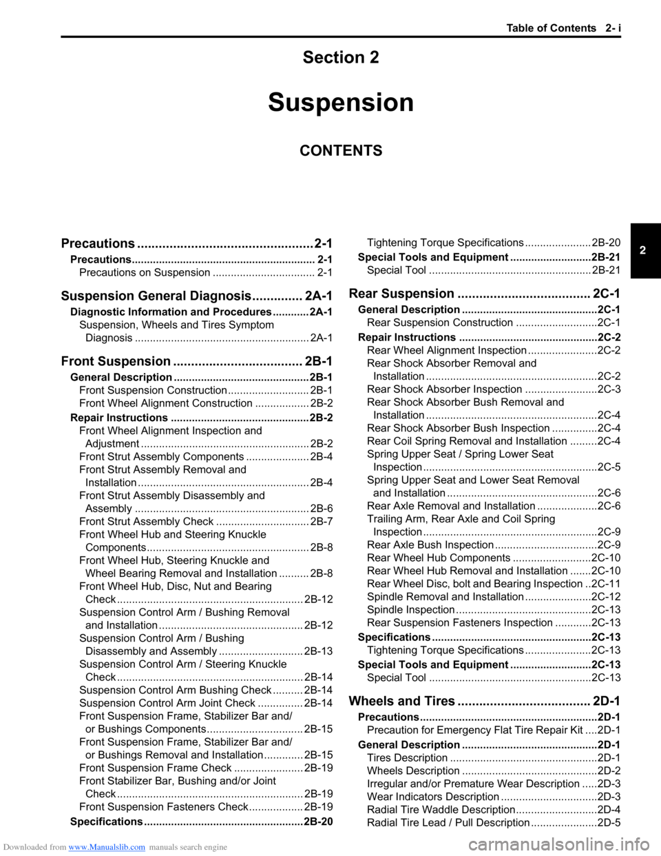
Suspension
Precautions ................................................. 2-1
Precautions............................................................. 2-1
Precautions on Suspension .................................. 2-1
Suspension General Dia gnosis.............. 2A-1
Diagnostic Information and Procedures ............ 2A-1
Suspension, Wheels and Tires Symptom Diagnosis .......................................................... 2A-1
Front Suspension ........... ......................... 2B-1
General Description ............................................. 2B-1
Front Suspension Construction ........................... 2B-1
Front Wheel Alignment Cons truction .................. 2B-2
Repair Instructions .............................................. 2B-2 Front Wheel Alignment Inspection and Adjustment ........................................................ 2B-2
Front Strut Assembly Comp onents ..................... 2B-4
Front Strut Assembly Removal and Installation ......................................................... 2B-4
Front Strut Assembly Disassembly and Assembly .......................................................... 2B-6
Front Strut Assembly Chec k ............................... 2B-7
Front Wheel Hub and Steering Knuckle Components...................................................... 2B-8
Front Wheel Hub, Steering Knuckle and Wheel Bearing Removal and Installation .......... 2B-8
Front Wheel Hub, Disc, Nut and Bearing Check .............................................................. 2B-12
Suspension Control Arm / Bushing Removal and Installation ................................................ 2B-12
Suspension Control Arm / Bushing Disassembly and Assembly ............................ 2B-13
Suspension Control Arm / Steering Knuckle Check .............................................................. 2B-14
Suspension Control Arm Bushing Check .......... 2B-14
Suspension Control Arm Joint Check ............... 2B-14
Front Suspension Fram e, Stabilizer Bar and/
or Bushings Components................................ 2B-15
Front Suspension Fram e, Stabilizer Bar and/
or Bushings Removal and Installation ............. 2B-15
Front Suspension Frame Ch eck ....................... 2B-19
Front Stabilizer Bar, Bushing and/or Joint Check .............................................................. 2B-19
Front Suspension Fastener s Check .................. 2B-19
Specifications ..................................................... 2B-20 Tightening Torque Specifications ...................... 2B-20
Special Tools and Equipmen t ...........................2B-21
Special Tool ...................................................... 2B-21
Rear Suspension ............ ......................... 2C-1
General Description .............................................2C-1
Rear Suspension Construction ...........................2C-1
Repair Instructions ........... ...................................2C-2
Rear Wheel Alignment Inspection .......................2C-2
Rear Shock Absorber Removal and Installation .........................................................2C-2
Rear Shock Absorber Ins pection ........................2C-3
Rear Shock Absorber Bush Removal and Installation .........................................................2C-4
Rear Shock Absorber Bush Inspection ...............2C-4
Rear Coil Spring Removal and Installation .........2C-4
Spring Upper Seat / Spring Lower Seat Inspection ..........................................................2C-5
Spring Upper Seat and Lower Seat Removal and Installation ..................................................2C-6
Rear Axle Removal and Inst allation ....................2C-6
Trailing Arm, Rear Axle and Coil Spring Inspection ..........................................................2C-9
Rear Axle Bush Inspection ..................................2C-9
Rear Wheel Hub Components ..........................2C-10
Rear Wheel Hub Removal an d Installation .......2C-10
Rear Wheel Disc, bolt and Bearing Inspection ..2C-11
Spindle Removal and Installation ......................2C-12
Spindle Inspection .............................................2C-13
Rear Suspension Fasteners Inspection ............2C-13
Specifications .................... .................................2C-13
Tightening Torque Specifications ......................2C-13
Special Tools and Equipmen t ...........................2C-13
Special Tool ......................................................2C-13
Wheels and Tires ............ ......................... 2D-1
Precautions...........................................................2D-1
Precaution for Emergency Flat Tire Repair Kit ....2D-1
General Description .............................................2D-1 Tires Description .................................................2D-1
Wheels Description .............................................2D-2
Irregular and/or Premature Wear Description .....2D-3
Wear Indicators Description ................................2D-3
Radial Tire Waddle Description...........................2D-4
Radial Tire Lead / Pull Description ......................2D-5
Page 432 of 1496
Downloaded from www.Manualslib.com manuals search engine 2A-1 Suspension General Diagnosis:
Suspension
Suspension General Diagnosis
Diagnostic Information and Procedures
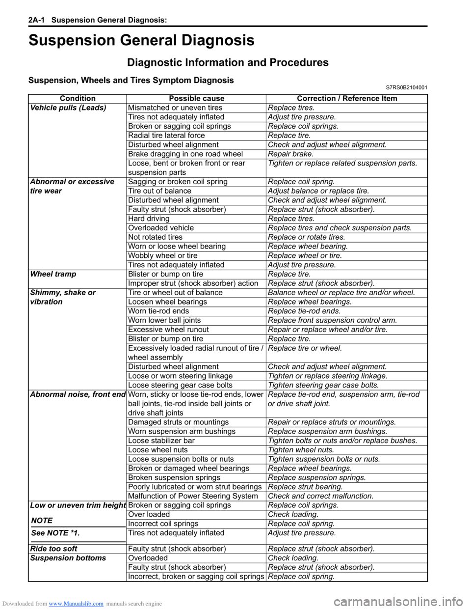
Suspension, Wheels and Tires Symptom DiagnosisS7RS0B2104001
ConditionPossible cause Correction / Reference Item
Vehicle pulls (Leads) Mismatched or uneven tires Replace tires.
Tires not adequately inflated Adjust tire pressure.
Broken or sagging coil springs Replace coil springs.
Radial tire lateral force Replace tire.
Disturbed wheel alignment Check and adjust wheel alignment.
Brake dragging in one road wheel Repair brake.
Loose, bent or broken front or rear
suspension parts Tighten or replace related suspension parts.
Abnormal or excessive
tire wear Sagging or broken coil spring
Replace coil spring.
Tire out of balance Adjust balance or replace tire.
Disturbed wheel alignment Check and adjust wheel alignment.
Faulty strut (shock absorber) Replace strut (shock absorber).
Hard driving Replace tires.
Overloaded vehicle Replace tires and check suspension parts.
Not rotated tires Replace or rotate tires.
Worn or loose wheel bearing Replace wheel bearing.
Wobbly wheel or tire Replace wheel or tire.
Tires not adequately inflated Adjust tire pressure.
Wheel tramp Blister or bump on tire Replace tire.
Improper strut (shock absorber) action Replace strut (shock absorber).
Shimmy, shake or
vibration Tire or wheel out of balance
Balance wheel or replace tire and/or wheel.
Loosen wheel bearings Replace wheel bearings.
Worn tie-rod ends Replace tie-rod ends.
Worn lower ball joints Replace front suspension control arm.
Excessive wheel runout Repair or replace wheel and/or tire.
Blister or bump on tire Replace tire.
Excessively loaded radial runout of tire /
wheel assembly Replace tire or wheel.
Disturbed wheel alignment Check and adjust wheel alignment.
Loose or worn steering linkage Tighten or replace steering linkage.
Loose steering gear case bolts Tighten steering gear case bolts.
Abnormal noise, front end Worn, sticky or loose tie-rod ends, lower
ball joints, tie-rod in side ball joints or
drive shaft joints Replace tie-rod end, su
spension arm, tie-rod
or drive shaft joint.
Damaged struts or mountings Repair or replace struts or mountings.
Worn suspension arm bushings Replace suspension arm bushings.
Loose stabilizer bar Tighten bolts or nuts and/or replace bushes.
Loose wheel nuts Tighten wheel nuts.
Loose suspension bolts or nuts Tighten suspension bolts or nuts.
Broken or damaged wheel bearings Replace wheel bearings.
Broken suspension springs Replace suspension springs.
Poorly lubricated or worn strut bearings Replace strut bearing.
Malfunction of Power Steering System Check and correct malfunction.
Low or uneven trim height
NOTE
See NOTE *1.
Broken or sagging coil springs Replace coil springs.
Over loaded Check loading.
Incorrect coil springs Replace coil spring.
Tires not adequately inflated Adjust tire pressure.
Ride too soft Faulty strut (shock absorber) Replace strut (shock absorber).
Suspension bottoms Overloaded Check loading.
Faulty strut (shock absorber) Replace strut (shock absorber).
Incorrect, broken or sagging coil springs Replace coil spring.
Page 433 of 1496
Downloaded from www.Manualslib.com manuals search engine Suspension General Diagnosis: 2A-2
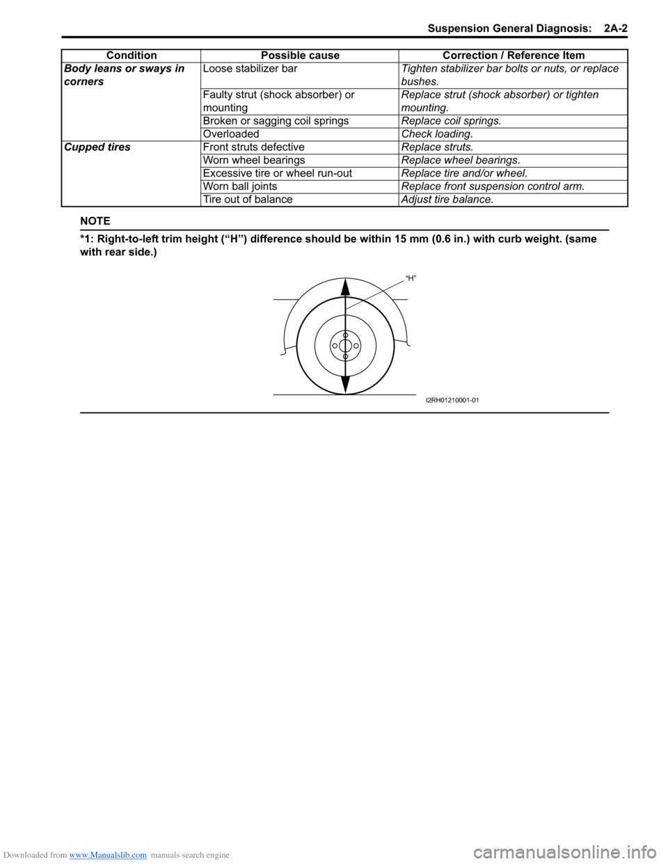
NOTE
*1: Right-to-left trim height (“H”) difference should be within 15 mm (0.6 in.) with curb weight. (same
with rear side.)
Body leans or sways in
corners Loose stabilizer bar
Tighten stabilizer bar bolts or nuts, or replace
bushes.
Faulty strut (shock absorber) or
mounting Replace strut (shock absorber) or tighten
mounting.
Broken or sagging coil springs Replace coil springs.
Overloaded Check loading.
Cupped tires Front struts defective Replace struts.
Worn wheel bearings Replace wheel bearings.
Excessive tire or wheel run-out Replace tire and/or wheel.
Worn ball joints Replace front suspension control arm.
Tire out of balance Adjust tire balance.
Condition Possible cause Correction / Reference Item
“H”
I2RH01210001-01
Page 434 of 1496
Downloaded from www.Manualslib.com manuals search engine 2B-1 Front Suspension:
Suspension
Front Suspension
General Description
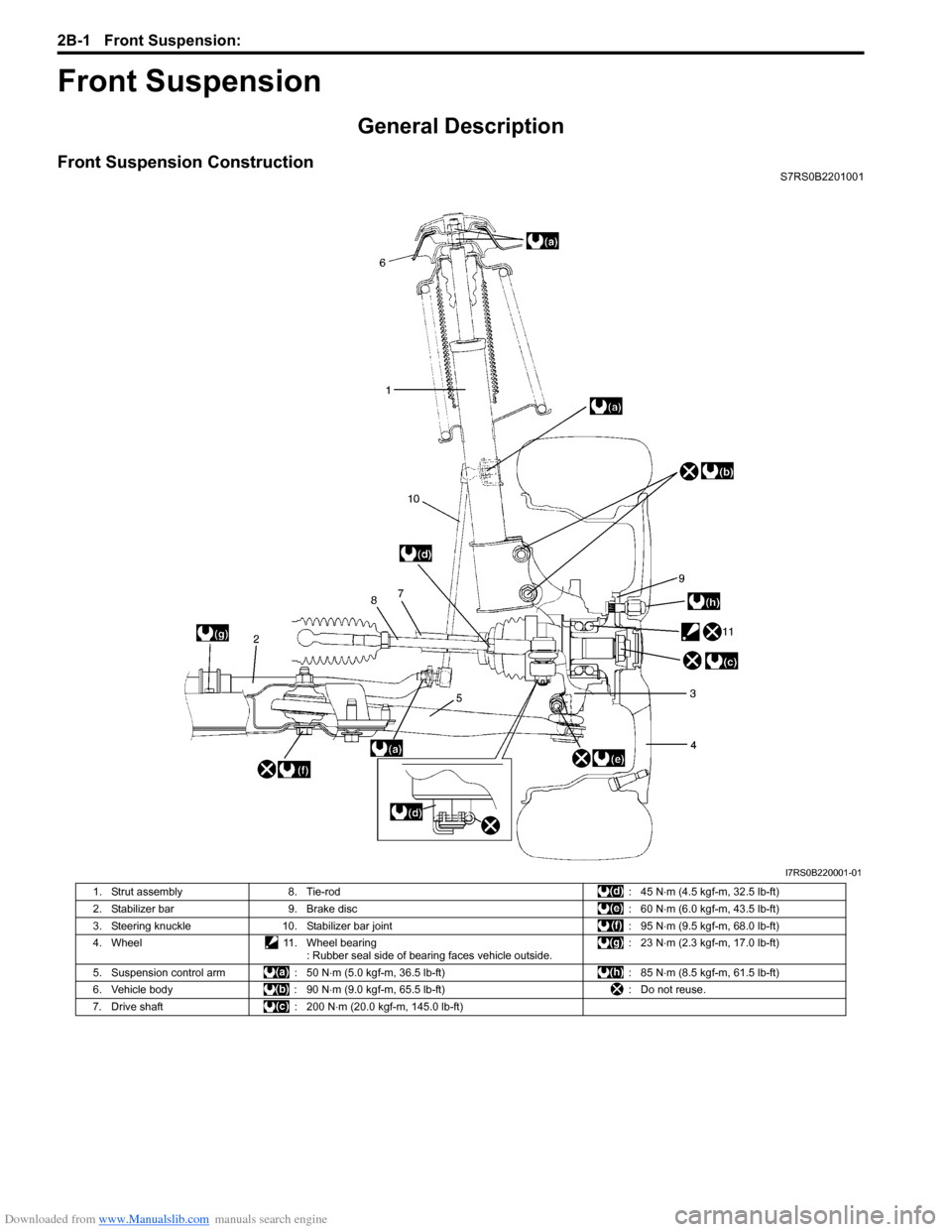
Front Suspension ConstructionS7RS0B2201001
I7RS0B220001-01
1. Strut assembly8. Tie-rod : 45 N⋅m (4.5 kgf-m, 32.5 lb-ft)
2. Stabilizer bar 9. Brake disc : 60 N⋅m (6.0 kgf-m, 43.5 lb-ft)
3. Steering knuckle 10. Stabilizer bar joint : 95 N⋅m (9.5 kgf-m, 68.0 lb-ft)
4. Wheel 11. Wheel bearing
: Rubber seal side of bearing faces vehicle outside. : 23 N
⋅m (2.3 kgf-m, 17.0 lb-ft)
5. Suspension control arm : 50 N⋅m (5.0 kgf-m, 36.5 lb-ft) : 85 N⋅m (8.5 kgf-m, 61.5 lb-ft)
6. Vehicle body : 90 N⋅m (9.0 kgf-m, 65.5 lb-ft) : Do not reuse.
7. Drive shaft : 200 N⋅m (20.0 kgf-m, 145.0 lb-ft)
Page 435 of 1496
Downloaded from www.Manualslib.com manuals search engine Front Suspension: 2B-2
Front Wheel Alignment ConstructionS7RS0B2201002
Among factors for front wheel alignment, only toe setting
can be adjusted. Camber and caster are not adjustable.
Therefore, should camber or caster be out of
specification due to the damage caused by hazardous
road conditions or collision, whether the damage is in
body or in suspension should be determined and
damaged body should be repaired or damaged
suspension should be replaced.
Preliminary Checks Prior to Adjustment Front Wheel
Alignment
Steering and vibration complaints are not always the
result of improper wheel alignment. An additional item to
be checked is the possibility of tire lead due to worn or
improperly manufactured tires. “Lead” is the vehicle
deviation from a straight path on a level road without
hand pressure on the steering wheel. Refer to “Radial
Tire Lead / Pull Description in Section 2D” in order to
determine if the vehicle has a tire lead problem. Before
making any adjustment affecting wheel alignment, the
following checks and inspections should be made to
ensure correctness of alignment readings and alignment
adjustments:
• Check all tires for proper inflation pressures and approximately the same tread wear. • Check for loose of ball join
ts. Check tie-rod ends; if
excessive looseness is noted, it must be corrected
before adjusting.
• Check for run-out of wheels and tires.
• Check vehicle trim heights; if it is out of limit and a
correction is needed, it must be done before adjusting
toe.
• Check for loose of suspension control arms.
• Check for loose or missin g stabilizer bar attachments.
• Consideration must be given to excess loads, such as
tool boxes. If this excess load is normally carried in
vehicle, it should remain in vehicle during alignment
checks.
• Consider condition of equipment being used to check alignment and follow manufa cturer’s instructions.
• Regardless of equipment used to check alignment, vehicle must be placed on a level surface.
NOTE
To prevent possible incorrect reading of toe,
camber or caster, vehicle front and rear end
must be moved up and down a few times
before inspection.
Repair Instructions
Front Wheel Alignment Inspection and
Adjustment
S7RS0B2206001
Toe Inspection and Adjustment
Preparation for toe inspection and adjustment.
• Place vehicle in unloaded state on level surface.
• Set steering wheel in straight state.
• Check that inflation pressure of each tire is adjusted properly and wheel is free from deflection.
• Check that each suspension part is free from bend, dent, wear or damage in any other form.
• Check that ground clearance at the right and left is just about the same.
Inspection
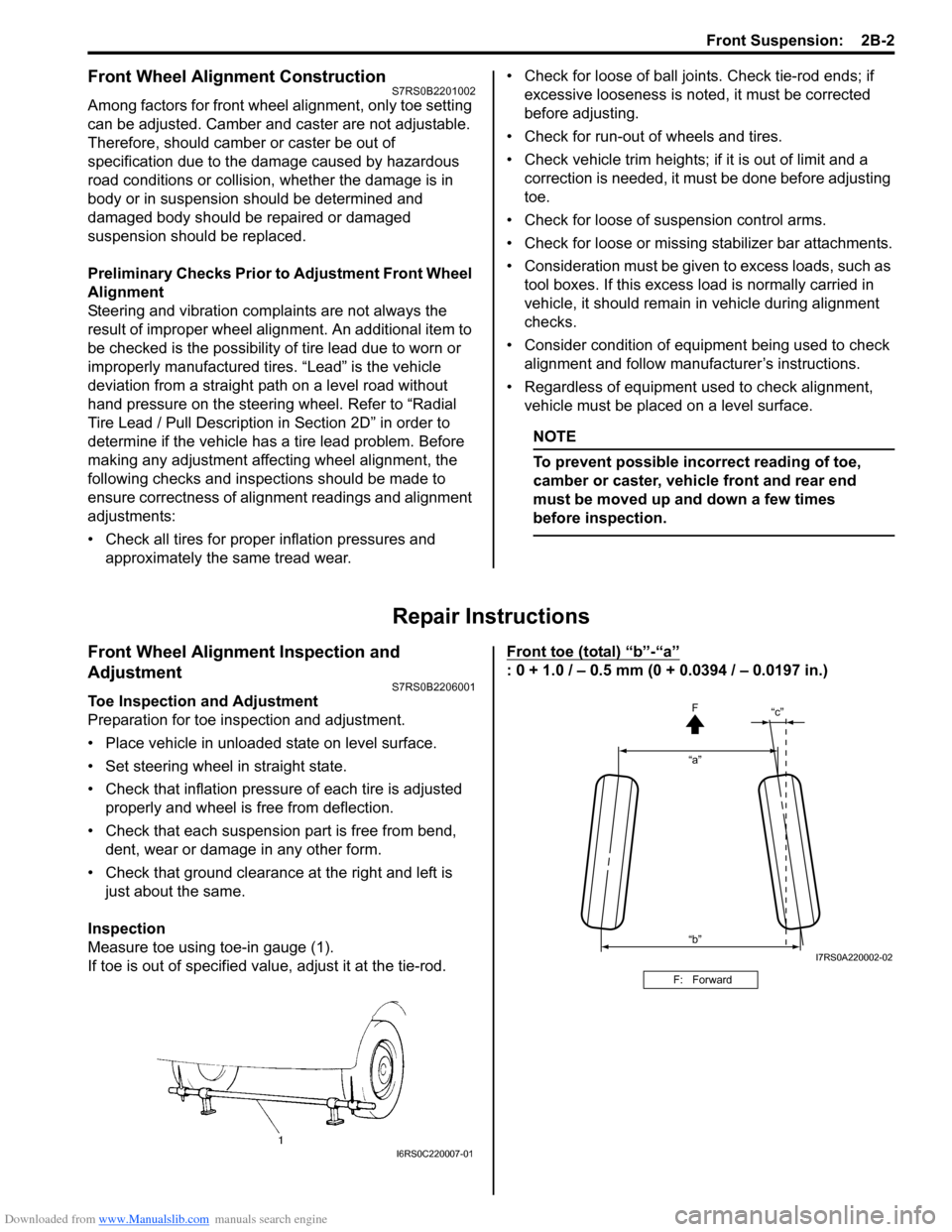
Measure toe using toe-in gauge (1).
If toe is out of specified value, adjust it at the tie-rod. Front toe (total) “b”-“a”
: 0 + 1.0 / – 0.5 mm (0 + 0.0394 / – 0.0197 in.)
I6RS0C220007-01
F: Forward
“a”
“c”
“b” F
I7RS0A220002-02