Defect SUZUKI SWIFT 2007 2.G Service Repair Manual
[x] Cancel search | Manufacturer: SUZUKI, Model Year: 2007, Model line: SWIFT, Model: SUZUKI SWIFT 2007 2.GPages: 1496, PDF Size: 34.44 MB
Page 854 of 1496
Downloaded from www.Manualslib.com manuals search engine 5C-2 Clutch:
Diagnostic Information and Procedures
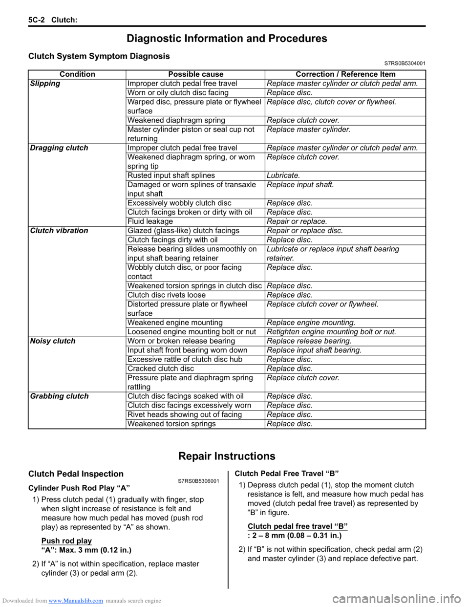
Clutch System Symptom DiagnosisS7RS0B5304001
Repair Instructions
Clutch Pedal InspectionS7RS0B5306001
Cylinder Push Rod Play тАЬAтАЭ1) Press clutch pedal (1) gradually with finger, stop when slight increase of resistance is felt and
measure how much pedal has moved (push rod
play) as represented by тАЬAтАЭ as shown.
Push rod play
тАЬAтАЭ: Max. 3 mm (0.12 in.)
2) If тАЬAтАЭ is not within specification, replace master cylinder (3) or pedal arm (2). Clutch Pedal Free Travel тАЬBтАЭ
1) Depress clutch pedal (1), stop the moment clutch resistance is felt, and measure how much pedal has
moved (clutch pedal free travel) as represented by
тАЬBтАЭ in figure.
Clutch pedal free travel
тАЬBтАЭ
: 2 тАУ 8 mm (0.08 тАУ 0.31 in.)
2) If тАЬBтАЭ is not within specification, check pedal arm (2) and master cylinder (3) and replace defective part.
Condition Possible cause Correction / Reference Item
Slipping Improper clutch pedal free travel Replace master cylinder or clutch pedal arm.
Worn or oily clutch disc facing Replace disc.
Warped disc, pressure plate or flywheel
surface Replace disc, clutch cover or flywheel.
Weakened diaphragm spring Replace clutch cover.
Master cylinder piston or seal cup not
returning Replace master cylinder.
Dragging clutch Improper clutch pedal free travel Replace master cylinder or clutch pedal arm.
Weakened diaphragm spring, or worn
spring tip Replace clutch cover.
Rusted input shaft splines Lubricate.
Damaged or worn splines of transaxle
input shaft Replace input shaft.
Excessively wobbly clutch disc Replace disc.
Clutch facings broken or dirty with oil Replace disc.
Fluid leakage Repair or replace.
Clutch vibration Glazed (glass-like) clutch facings Repair or replace disc.
Clutch facings dirty with oil Replace disc.
Release bearing slides unsmoothly on
input shaft bearing retainer Lubricate or replace input shaft bearing
retainer.
Wobbly clutch disc, or poor facing
contact Replace disc.
Weakened torsion springs in clutch disc Replace disc.
Clutch disc rivets loose Replace disc.
Distorted pressure plate or flywheel
surface Replace clutch cover or flywheel.
Weakened engine mounting Replace engine mounting.
Loosened engine mounting bolt or nut Retighten engine mounting bolt or nut.
Noisy clutch Worn or broken release bearing Replace release bearing.
Input shaft front bearing worn down Replace input shaft bearing.
Excessive rattle of clutch disc hub Replace disc.
Cracked clutch disc Replace disc.
Pressure plate and diaphragm spring
rattling Replace clutch cover.
Grabbing clutch Clutch disc facings soaked with oil Replace disc.
Clutch disc facings excessively worn Replace disc.
Rivet heads showing out of facing Replace disc.
Weakened torsion springs Replace disc.
Page 870 of 1496
Downloaded from www.Manualslib.com manuals search engine 6A-1 Steering General Diagnosis:
Steeri ng
Steering General Diagnosis
Precautions
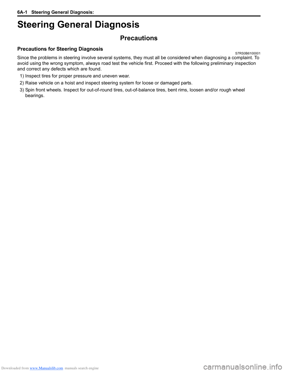
Precautions for Steering DiagnosisS7RS0B6100001
Since the problems in steering involve several systems, they must all be considered when diagnosing a complaint. To
avoid using the wrong symptom, always road test the vehicl e first. Proceed with the following preliminary inspection
and correct any defects which are found.
1) Inspect tires for proper pressure and uneven wear.
2) Raise vehicle on a hoist and inspect steering system for loose or damaged parts.
3) Spin front wheels. Inspect for out-of-round tires, out- of-balance tires, bent rims, loosen and/or rough wheel
bearings.
Page 873 of 1496
Downloaded from www.Manualslib.com manuals search engine Steering Wheel and Column: 6B-2
Diagnostic Information and Procedures
Checking Steering Column for Accident
Damage
S7RS0B6204001
NOTE
Vehicles involved in accidents resulting in
body damage, where steering column has
been impacted or air bag deployed may have
a damaged or misaligned steering column.
Checking Procedure
NOTE
The steering column used in each vehicle is
one of the two types as shown.
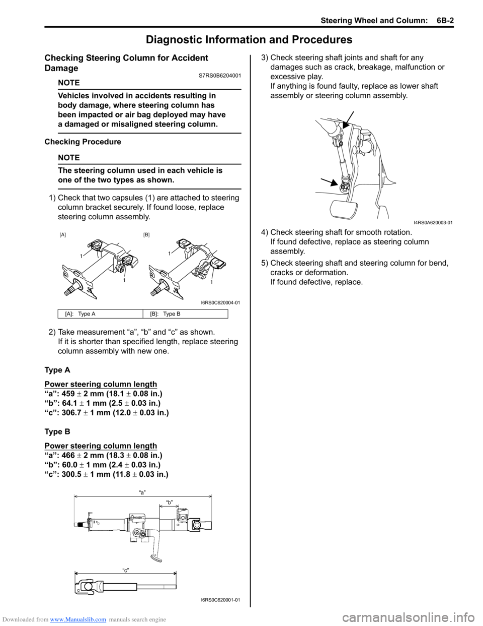
1) Check that two capsules (1) are attached to steering column bracket securely. If found loose, replace
steering column assembly.
2) Take measurement тАЬaтАЭ, тАЬbтАЭ and тАЬcтАЭ as shown. If it is shorter than spec ified length, replace steering
column assembly with new one.
Ty p e A
Power steering column length
тАЬaтАЭ: 459 ┬▒ 2 mm (18.1 ┬▒ 0.08 in.)
тАЬbтАЭ: 64.1 ┬▒ 1 mm (2.5 ┬▒ 0.03 in.)
тАЬcтАЭ: 306.7 ┬▒ 1 mm (12.0 ┬▒ 0.03 in.)
Ty p e B
Power steering column length
тАЬaтАЭ: 466 ┬▒ 2 mm (18.3 ┬▒ 0.08 in.)
тАЬbтАЭ: 60.0 ┬▒ 1 mm (2.4 ┬▒ 0.03 in.)
тАЬcтАЭ: 300.5 ┬▒ 1 mm (11.8 ┬▒ 0.03 in.) 3) Check steering shaft joints and shaft for any
damages such as crack, breakage, malfunction or
excessive play.
If anything is found faulty, replace as lower shaft
assembly or steering column assembly.
4) Check steering shaft for smooth rotation. If found defective, replace as steering column
assembly.
5) Check steering shaft and steering column for bend, cracks or deformation.
If found defective, replace.
[A]: Type A [B]: Type B
[A] [B]
1
1
1
1
I6RS0C620004-01
I6RS0C620001-01
I4RS0A620003-01
Page 896 of 1496
Downloaded from www.Manualslib.com manuals search engine 6C-14 Power Assisted Steering System:
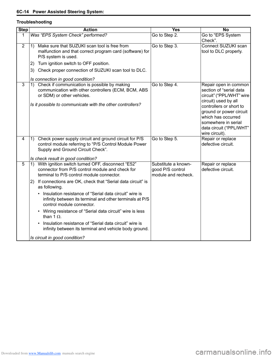
TroubleshootingStep Action Yes No 1 Was тАЬEPS System CheckтАЭ performed? Go to Step 2. Go to тАЬEPS System
CheckтАЭ.
2 1) Make sure that SUZUKI scan tool is free from malfunction and that correct program card (software) for
P/S system is used.
2) Turn ignition switch to OFF position.
3) Check proper connection of SUZUKI scan tool to DLC.
Is connection in good condition? Go to Step 3. Connect SUZUKI scan
tool to DLC properly.
3 1) Check if communication is possible by making communication with other controllers (ECM, BCM, ABS
or SDM) or other vehicles.
Is it possible to communic ate with the other controllers? Go to Step 4. Repair open in common
section of тАЬserial data
circuitтАЭ (тАЬPPL/WHTтАЭ wire
circuit) used by all
controllers or short to
ground or power circuit
which has occurred
somewhere in serial
data circuit (тАЬPPL/WHTтАЭ
wire circuit).
4 1) Check power supply circuit and ground circuit for P/S control module referring to тАЬP/S Control Module Power
Supply and Ground Circuit CheckтАЭ.
Is check result in good condition? Go to Step 5. Repair or replace
defective circuit.
5 1) With ignition switch turned OFF, disconnect тАЬE52тАЭ connector from P/S control module and check for
terminal to P/S control module connector.
2) If connections are OK, check t hat тАЬSerial data circuitтАЭ is
as following.
тАв Insulation resistance of тАЬSerial data circuitтАЭ wire is infinity between its terminal and other terminals at P/S
control module connector.
тАв Wiring resistance of тАЬSeria l data circuitтАЭ wire is less
than 1 тДж.
тАв Insulation resistance of тАЬSerial data circuitтАЭ wire is infinity between its terminal and vehicle body ground.
Is circuit in good condition? Substitute a known-
good P/S control
module and recheck.
Repair or replace
defective circuit.
Page 897 of 1496
Downloaded from www.Manualslib.com manuals search engine Power Assisted Steering System: 6C-15
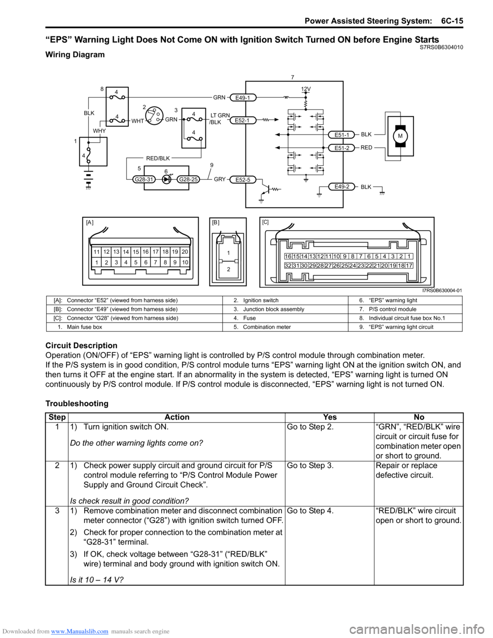
тАЬEPSтАЭ Warning Light Does Not Come ON with Ignition Switch Turned ON before Engine StartsS7RS0B6304010
Wiring Diagram
Circuit Description
Operation (ON/OFF) of тАЬEPSтАЭ warning light is controlled by P/S control module through combination meter.
If the P/S system is in good condition, P/S control module turns тАЬ EPSтАЭ warning light ON at the ignition switch ON, and
then turns it OFF at the engine start. If an abnormality in the system is detected, тАЬEPSтАЭ warning light is turned ON
continuously by P/S control module. If P/S control module is disconnected, тАЬEPSтАЭ warning light is not turned ON.
Troubleshooting
MBLK
REDE51-1
E51-2
[A ]
12 3
4 5 67
89
11
10
12 13
141516
17 18 19 2010 9 8 7654 3 21
16 15 14 13 12 11
26 25 24 2322 21 20 19 18 17
32 31 30 29 28 27
[C]
7
12V
E49-2BLK
[B ]
1 2
GRY
LT GRN
/BLK
E52-1
E52-5
E49-1
GRNGRNWHTBLK
WHY
G28-25G28-31
RED/BLK
8
3
4
4
5 6
4
4
1 2
4
9
I7RS0B630004-01
[A]: Connector тАЬE52тАЭ (viewed from harness side) 2. Ignition switch6. тАЬEPSтАЭ warning light
[B]: Connector тАЬE49тАЭ (viewed from harness side) 3. Junction block assembly7. P/S control module
[C]: Connector тАЬG28тАЭ (viewed from harness si de)4. Fuse 8. Individual circuit fuse box No.1
1. Main fuse box 5. Combination meter9. тАЬEPSтАЭ warning light circuit
StepAction YesNo
1 1) Turn ignition switch ON.
Do the other warning lights come on? Go to Step 2.
тАЬGRNтАЭ, тАЬRED/BLKтАЭ wire
circuit or circuit fuse for
combination meter open
or short to ground.
2 1) Check power supply circuit and ground circuit for P/S control module referring to тАЬP/S Control Module Power
Supply and Ground Circuit CheckтАЭ.
Is check result in good condition? Go to Step 3.
Repair or replace
defective circuit.
3 1) Remove combination meter and disconnect combination meter connector (тАЬG28тАЭ) with ignition switch turned OFF.
2) Check for proper connection to the combination meter at тАЬG28-31тАЭ terminal.
3) If OK, check voltage between тАЬG28-31тАЭ (тАЬRED/BLKтАЭ wire) terminal and body ground with ignition switch ON.
Is it 10 тАУ 14 V? Go to Step 4.
тАЬRED/BLKтАЭ wire circuit
open or short to ground.
Page 900 of 1496
Downloaded from www.Manualslib.com manuals search engine 6C-18 Power Assisted Steering System:
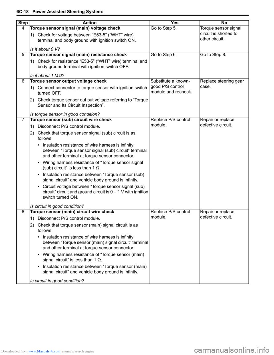
4Torque sensor signal (main) voltage check
1) Check for voltage between тАЬE53-5тАЭ (тАЬWHTтАЭ wire)
terminal and body ground with ignition switch ON.
Is it about 0 V? Go to Step 5. Torque sensor signal
circuit is shorted to
other circuit.
5 Torque sensor signal (main) resistance check
1) Check for resistance тАЬE53-5тАЭ (тАЬWHTтАЭ wire) terminal and
body ground terminal with ignition switch OFF.
Is it about 1 M
тДж? Go to Step 6. Go to Step 8.
6 Torque sensor output voltage check
1) Connect connector to torque sensor with ignition switch
turned OFF.
2) Check torque sensor out put voltage referring to тАЬTorque Sensor and Its Circuit InspectionтАЭ.
Is torque sensor in good condition? Substitute a known-
good P/S control
module and recheck.
Replace steering gear
case.
7 Torque sensor (sub) circuit wire check
1) Disconnect P/S control module.
2) Check that torque sensor signal (sub) circuit is as
follows.
тАв Insulation resistance of wire harness is infinity between тАЬTorque sensor signal (sub) circuitтАЭ terminal
and other terminal at torque sensor connector.
тАв Wiring harness resistance of тАЬTorque sensor signal (sub) circuitтАЭ is less than 1 тДж.
тАв Insulation resistance between тАЬTorque sensor (sub) signal circuitтАЭ and vehicle body ground is infinity.
тАв Circuit voltage between тАЬTorque sensor signal (sub) circuitтАЭ circuit and ground circuit is 0 тАУ 1 V with ignition
switch turned ON.
Is circuit in good condition? Replace P/S control
module.
Repair or replace
defective circuit.
8 Torque sensor (main) circuit wire check
1) Disconnect P/S control module.
2) Check that torque sensor (main) signal circuit is as
follows.
тАв Insulation resistance of wire harness is infinity between тАЬTorque sensor (main) signal circuitтАЭ terminal
and other terminal at torque sensor connector.
тАв Wiring harness resistance of тАЬTorque sensor (main) signal circuitтАЭ is less than 1 тДж.
тАв Insulation resistance between тАЬTorque sensor (main) signal circuitтАЭ and vehicle body ground is infinity.
Is circuit in good condition? Replace P/S control
module.
Repair or replace
defective circuit.
Step Action Yes No
Page 902 of 1496
Downloaded from www.Manualslib.com manuals search engine 6C-20 Power Assisted Steering System:
DTC TroubleshootingStep Action Yes No 1 Was тАЬEPS System CheckтАЭ performed? Go to Step 2. Go to тАЬEPS System
CheckтАЭ.
2 DTC check
Is DTC C1153 and/or DTC C1155 indicated together? Go to applicable DTC
diag. flow.
Go to Step 3.
3 Torque sensor 5 V reference power supply circuit
voltage check
1) With ignition switch turned OFF, disconnect torque
sensor connector and check for proper terminal
connection to torque sensor connector.
2) If connections are OK, check for voltage between тАЬE53- 6тАЭ (тАЬREDтАЭ wire) terminal and body ground with ignition
switch ON.
Is it approx. 5 V? Go to Step 4. Go to Step 5.
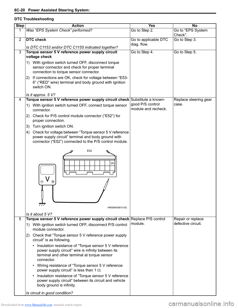
4 Torque sensor 5 V reference power supply circuit check
1) With ignition switch turned OFF, connect torque sensor
connector.
2) Check for P/S control module connector (тАЬE52тАЭ) for proper connection.
3) Turn ignition switch ON.
4) Check for voltage between тАЬTorque sensor 5 V reference power supply circuitтАЭ terminal and body ground with
connector (тАЬE52тАЭ) connected to the P/S control module.
Is it about 5 V? Substitute a known-
good P/S control
module and recheck.
Replace steering gear
case.
5 Torque sensor 5 V reference power supply circuit check
1) With ignition switch turned OFF, disconnect P/S control
module connector.
2) Check that тАЬTorque sensor 5 V reference power supply circuitтАЭ is as following.
тАв Insulation resistance of тАЬTorque sensor 5 V reference power supply circuitтАЭ wire is infinity between its
terminal and other terminal at torque sensor
connector.
тАв Wiring resistance of тАЬTorque sensor 5 V reference power supply circuitтАЭ is less than 1 тДж.
тАв Insulation resistance of тАЬTorque sensor 5 V reference power supply circuitтАЭ between its circuit and vehicle
body ground is infinity.
Is circuit in good condition? Replace P/S control
module.
Repair or replace
defective circuit.
20
E52
I4RS0A630013-02
Page 904 of 1496
Downloaded from www.Manualslib.com manuals search engine 6C-22 Power Assisted Steering System:
DTC Troubleshooting
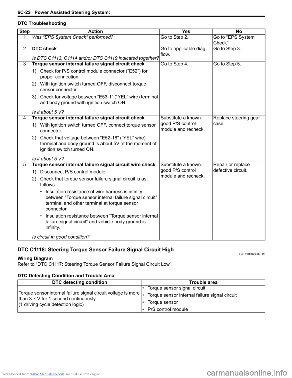
DTC C1118: Steering Torque Sensor Failure Signal Circuit HighS7RS0B6304015
Wiring Diagram
Refer to тАЬDTC C1117: Steering Torque Sensor Failure Signal Circuit LowтАЭ.
DTC Detecting Condition and Trouble AreaStep Action Yes No
1 Was тАЬEPS System CheckтАЭ performed? Go to Step 2. Go to тАЬEPS System
CheckтАЭ.
2 DTC check
Is DTC C1113, C1114 and/or DTC C1119 indicated together? Go to applicable diag.
flow.
Go to Step 3.
3 Torque sensor internal failure signal circuit check
1) Check for P/S control module connector (тАЬE52тАЭ) for
proper connection.
2) With ignition switch turned OFF, disconnect torque sensor connector.
3) Check for voltage between тАЬE53-1тАЭ (тАЬYELтАЭ wire) terminal and body ground with ignition switch ON.
Is it about 5 V? Go to Step 4. Go to Step 5.
4 Torque sensor internal failure signal circuit check
1) With ignition switch turned OFF, connect torque sensor
connector.
2) Check that voltage between тАЬE52-16тАЭ (тАЬYELтАЭ wire) terminal and body ground is about 5V at the moment of
ignition switch turned ON.
Is it about 5 V? Substitute a known-
good P/S control
module and recheck.
Replace steering gear
case.
5 Torque sensor internal failure signal circuit wire check
1) Disconnect P/S control module.
2) Check that torque sensor failure signal circuit is as
follows.
тАв Insulation resistance of wire harness is infinity between тАЬTorque sensor internal failure signal circuitтАЭ
terminal and other terminal at torque sensor
connector.
тАв Insulation resistance between тАЬTorque sensor internal failure signal circuitтАЭ and vehicle body ground is
infinity.
Is circuit in good condition? Substitute a known-
good P/S control
module and recheck.
Repair or replace
defective circuit.
DTC detecting condition
Trouble area
Torque sensor internal failure signal circuit voltage is more
than 3.7 V for 1 second continuously
(1 driving cycle detection logic) тАв Torque sensor signal circuit
тАв Torque sensor internal failure signal circuit
тАв Torque sensor
тАв P/S control module
Page 905 of 1496
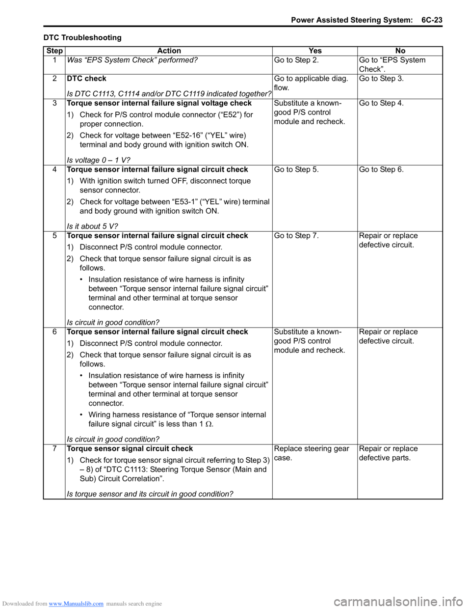
Downloaded from www.Manualslib.com manuals search engine Power Assisted Steering System: 6C-23
DTC TroubleshootingStep Action Yes No 1 Was тАЬEPS System CheckтАЭ performed? Go to Step 2. Go to тАЬEPS System
CheckтАЭ.
2 DTC check
Is DTC C1113, C1114 and/or DTC C1119 indicated together? Go to applicable diag.
flow.
Go to Step 3.
3 Torque sensor internal failure signal voltage check
1) Check for P/S control module connector (тАЬE52тАЭ) for
proper connection.
2) Check for voltage between тАЬE52-16тАЭ (тАЬYELтАЭ wire) terminal and body ground with ignition switch ON.
Is voltage 0 тАУ 1 V? Substitute a known-
good P/S control
module and recheck.
Go to Step 4.
4 Torque sensor internal failure signal circuit check
1) With ignition switch turned OFF, disconnect torque
sensor connector.
2) Check for voltage between тАЬE53-1тАЭ (тАЬYELтАЭ wire) terminal and body ground with ignition switch ON.
Is it about 5 V? Go to Step 5. Go to Step 6.
5 Torque sensor internal failure signal circuit check
1) Disconnect P/S control module connector.
2) Check that torque sensor failure signal circuit is as
follows.
тАв Insulation resistance of wire harness is infinity between тАЬTorque sensor internal failure signal circuitтАЭ
terminal and other terminal at torque sensor
connector.
Is circuit in good condition? Go to Step 7. Repair or replace
defective circuit.
6 Torque sensor internal failure signal circuit check
1) Disconnect P/S control module connector.
2) Check that torque sensor failure signal circuit is as
follows.
тАв Insulation resistance of wire harness is infinity between тАЬTorque sensor internal failure signal circuitтАЭ
terminal and other terminal at torque sensor
connector.
тАв Wiring harness resistance of тАЬTorque sensor internal failure signal circuitтАЭ is less than 1 тДж.
Is circuit in good condition? Substitute a known-
good P/S control
module and recheck.
Repair or replace
defective circuit.
7 Torque sensor signal circuit check
1) Check for torque sensor signal circuit referring to Step 3)
тАУ 8) of тАЬDTC C1113: Steering Torque Sensor (Main and
Sub) Circuit CorrelationтАЭ.
Is torque sensor and its circuit in good condition? Replace steering gear
case.
Repair or replace
defective parts.
Page 907 of 1496
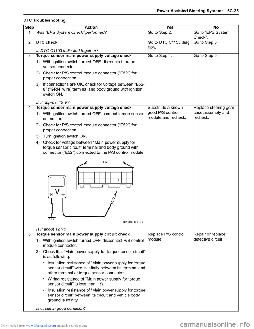
Downloaded from www.Manualslib.com manuals search engine Power Assisted Steering System: 6C-25
DTC TroubleshootingStep Action Yes No 1 Was тАЬEPS System CheckтАЭ performed? Go to Step 2. Go to тАЬEPS System
CheckтАЭ.
2 DTC check
Is DTC C1153 indicated together? Go to DTC C1153 diag.
flow.
Go to Step 3.
3 Torque sensor main power supply voltage check
1) With ignition switch turned OFF, disconnect torque
sensor connector.
2) Check for P/S control module connector (тАЬE52тАЭ) for proper connection.
3) If connections are OK, check for voltage between тАЬE52- 8тАЭ (тАЬGRNтАЭ wire) terminal and body ground with ignition
switch ON.
Is it approx. 12 V? Go to Step 4. Go to Step 5.
4 Torque sensor main power supply voltage check
1) With ignition switch turned OFF, connect torque sensor
connector.
2) Check for P/S control module connector (тАЬE52тАЭ) for proper connection.
3) Turn ignition switch ON.
4) Check for voltage between тАЬMain power supply for torque sensor circuitтАЭ terminal and body ground with
connector (тАЬE52тАЭ) connected to the P/S control module.
Is it about 12 V? Substitute a known-
good P/S control
module and recheck.
Replace steering gear
case assembly and
recheck.
5 Torque sensor main power supply circuit check
1) With ignition switch turned OFF, disconnect P/S control
module connector.
2) Check that тАЬMain power supply for torque sensor circuitтАЭ is as following.
тАв Insulation resistance of тАЬMain power supply for torque sensor circuitтАЭ wire is infinity between its terminal and
other terminal at torque sensor connector.
тАв Wiring resistance of тАЬMain power supply for torque sensor circuitтАЭ is less than 1 тДж .
тАв Insulation resistance of тАЬMain power supply for torque sensor circuitтАЭ between its circuit and vehicle body
ground is infinity.
Is circuit in good condition? Replace P/S control
module.
Repair or replace
defective circuit.
8
E52
I4RS0A630021-02