relay SUZUKI SX4 2006 1.G Service Workshop Manual
[x] Cancel search | Manufacturer: SUZUKI, Model Year: 2006, Model line: SX4, Model: SUZUKI SX4 2006 1.GPages: 1556, PDF Size: 37.31 MB
Page 987 of 1556
Downloaded from www.Manualslib.com manuals search engine Air Conditioning System: Automatic Type 7B-47
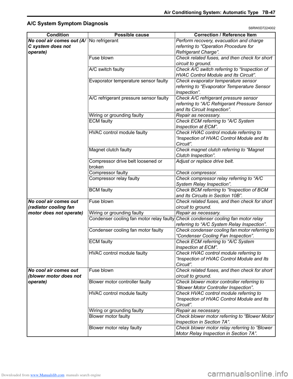
A/C System Symptom DiagnosisS6RW0D7224002
Condition Possible cause Correction / Reference Item
No cool air comes out (A/
C system does not
operate)No refrigerantPerform recovery, evacuation and charge
referring to “Operation Procedure for
Refrigerant Charge”.
Fuse blownCheck related fuses, and then check for short
circuit to ground.
A/C switch faultyCheck A/C switch referring to “Inspection of
HVAC Control Module and Its Circuit”.
Evaporator temperature sensor faultyCheck evaporator temperature sensor
referring to “Evaporator Temperature Sensor
Inspection”.
A/C refrigerant pressure sensor faultyCheck A/C refrigerant pressure sensor
referring to “A/C Refrigerant Pressure Sensor
and Its Circuit Inspection”.
Wiring or grounding faultyRepair as necessary.
ECM faultyCheck ECM referring to “A/C System
Inspection at ECM”.
HVAC control module faultyCheck HVAC control module referring to
“Inspection of HVAC Control Module and Its
Circuit”.
Magnet clutch faultyCheck magnet clutch referring to “Magnet
Clutch Inspection”.
Compressor drive belt loosened or
brokenAdjust or replace drive belt.
Compressor faultyCheck compressor.
Compressor relay faultyCheck compressor relay referring to “A/C
System Relay Inspection”.
BCM faultyCheck BCM referring to “Inspection of BCM
and Its Circuits in Section 10B”.
No cool air comes out
(radiator cooling fan
motor does not operate)Fuse blownCheck related fuses, and then check for short
circuit to ground.
Wiring or grounding faultyRepair as necessary.
Condenser cooling fan motor relay faultyCheck condenser cooling fan motor relay
referring to “A/C System Relay Inspection”.
Condenser cooling fan motor faultyCheck condenser cooling fan motor referring to
“Condenser Cooling Fan Inspection”.
ECM faultyCheck ECM referring to “A/C System
Inspection at ECM”.
HVAC control module faultyCheck HVAC control module referring to
“Inspection of HVAC Control Module and Its
Circuit”.
No cool air comes out
(blower motor does not
operate)Fuse blownCheck related fuses, and then check for short
circuit to ground.
Blower motor controller faultyCheck blower motor controller referring to
“Blower Motor Controller Inspection”.
HVAC control module faultyCheck HVAC control module referring to
“Inspection of HVAC Control Module and Its
Circuit”.
Wiring or grounding faultyRepair as necessary.
Blower motor faultyCheck blower motor referring to “Blower Motor
Inspection in Section 7A”.
Blower motor relay faultyCheck blower motor relay referring to “Blower
Motor Relay Inspection in Section 7A”.
Page 1027 of 1556
Downloaded from www.Manualslib.com manuals search engine Air Conditioning System: Automatic Type 7B-87
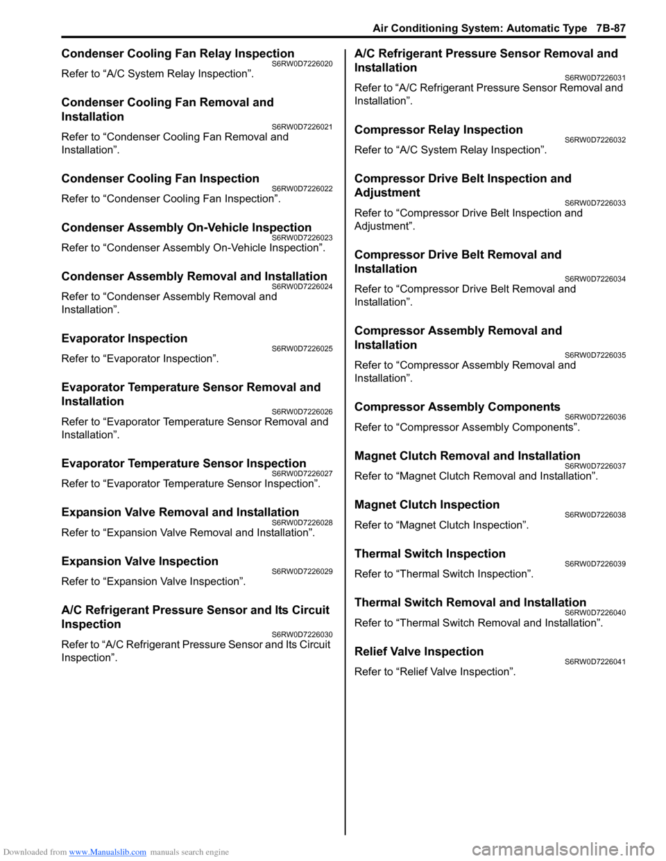
Condenser Cooling Fan Relay InspectionS6RW0D7226020
Refer to “A/C System Relay Inspection”.
Condenser Cooling Fan Removal and
Installation
S6RW0D7226021
Refer to “Condenser Cooling Fan Removal and
Installation”.
Condenser Cooling Fan InspectionS6RW0D7226022
Refer to “Condenser Cooling Fan Inspection”.
Condenser Assembly On-Vehicle InspectionS6RW0D7226023
Refer to “Condenser Assembly On-Vehicle Inspection”.
Condenser Assembly Removal and InstallationS6RW0D7226024
Refer to “Condenser Assembly Removal and
Installation”.
Evaporator InspectionS6RW0D7226025
Refer to “Evaporator Inspection”.
Evaporator Temperature Sensor Removal and
Installation
S6RW0D7226026
Refer to “Evaporator Temperature Sensor Removal and
Installation”.
Evaporator Temperature Sensor InspectionS6RW0D7226027
Refer to “Evaporator Temperature Sensor Inspection”.
Expansion Valve Removal and InstallationS6RW0D7226028
Refer to “Expansion Valve Removal and Installation”.
Expansion Valve InspectionS6RW0D7226029
Refer to “Expansion Valve Inspection”.
A/C Refrigerant Pressure Sensor and Its Circuit
Inspection
S6RW0D7226030
Refer to “A/C Refrigerant Pressure Sensor and Its Circuit
Inspection”.
A/C Refrigerant Pressure Sensor Removal and
Installation
S6RW0D7226031
Refer to “A/C Refrigerant Pressure Sensor Removal and
Installation”.
Compressor Relay InspectionS6RW0D7226032
Refer to “A/C System Relay Inspection”.
Compressor Drive Belt Inspection and
Adjustment
S6RW0D7226033
Refer to “Compressor Drive Belt Inspection and
Adjustment”.
Compressor Drive Belt Removal and
Installation
S6RW0D7226034
Refer to “Compressor Drive Belt Removal and
Installation”.
Compressor Assembly Removal and
Installation
S6RW0D7226035
Refer to “Compressor Assembly Removal and
Installation”.
Compressor Assembly ComponentsS6RW0D7226036
Refer to “Compressor Assembly Components”.
Magnet Clutch Removal and InstallationS6RW0D7226037
Refer to “Magnet Clutch Removal and Installation”.
Magnet Clutch InspectionS6RW0D7226038
Refer to “Magnet Clutch Inspection”.
Thermal Switch InspectionS6RW0D7226039
Refer to “Thermal Switch Inspection”.
Thermal Switch Removal and InstallationS6RW0D7226040
Refer to “Thermal Switch Removal and Installation”.
Relief Valve InspectionS6RW0D7226041
Refer to “Relief Valve Inspection”.
Page 1163 of 1556
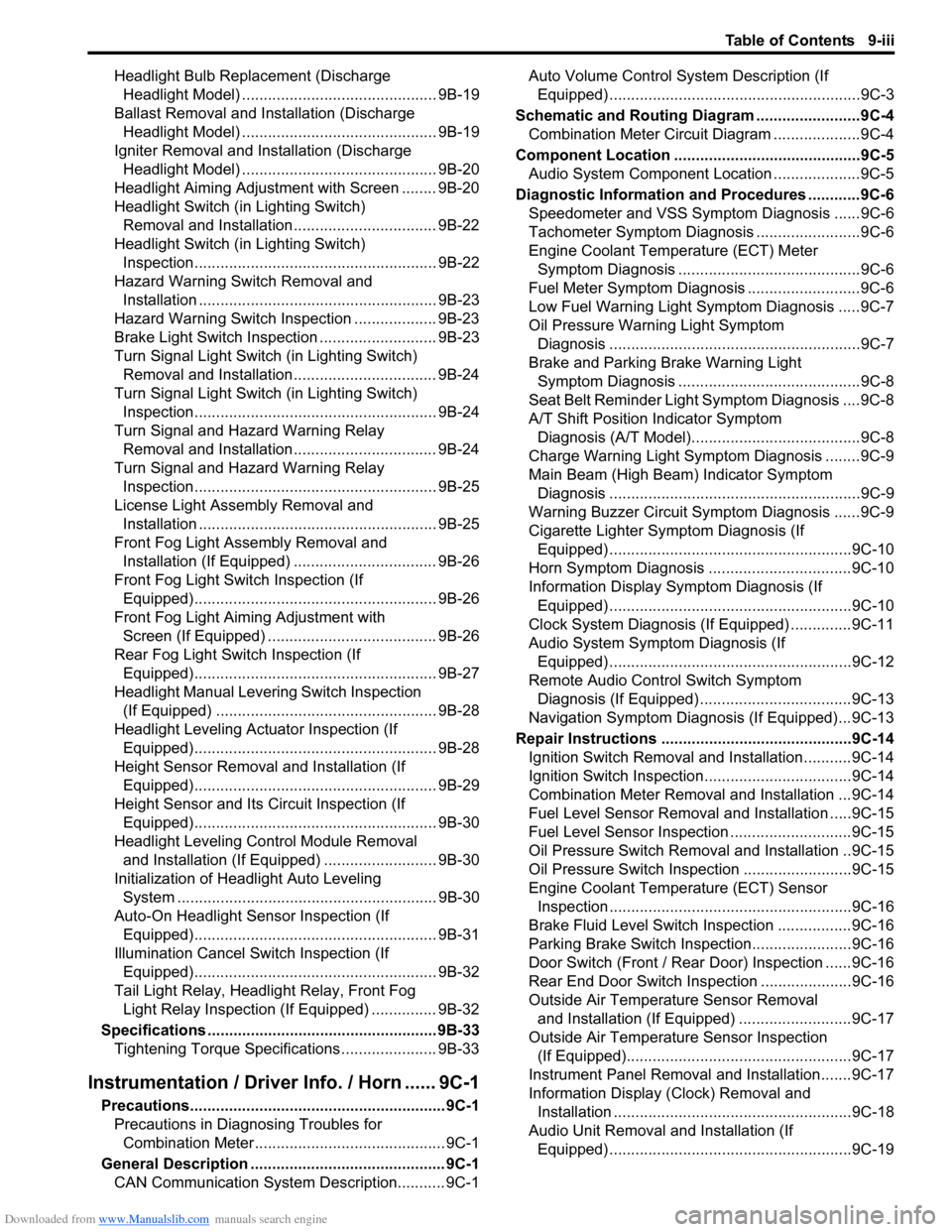
Downloaded from www.Manualslib.com manuals search engine Table of Contents 9-iii
Headlight Bulb Replacement (Discharge
Headlight Model) ............................................. 9B-19
Ballast Removal and Installation (Discharge
Headlight Model) ............................................. 9B-19
Igniter Removal and Installation (Discharge
Headlight Model) ............................................. 9B-20
Headlight Aiming Adjustment with Screen ........ 9B-20
Headlight Switch (in Lighting Switch)
Removal and Installation................................. 9B-22
Headlight Switch (in Lighting Switch)
Inspection........................................................ 9B-22
Hazard Warning Switch Removal and
Installation ....................................................... 9B-23
Hazard Warning Switch Inspection ................... 9B-23
Brake Light Switch Inspection ........................... 9B-23
Turn Signal Light Switch (in Lighting Switch)
Removal and Installation................................. 9B-24
Turn Signal Light Switch (in Lighting Switch)
Inspection........................................................ 9B-24
Turn Signal and Hazard Warning Relay
Removal and Installation................................. 9B-24
Turn Signal and Hazard Warning Relay
Inspection........................................................ 9B-25
License Light Assembly Removal and
Installation ....................................................... 9B-25
Front Fog Light Assembly Removal and
Installation (If Equipped) ................................. 9B-26
Front Fog Light Switch Inspection (If
Equipped)........................................................ 9B-26
Front Fog Light Aiming Adjustment with
Screen (If Equipped) ....................................... 9B-26
Rear Fog Light Switch Inspection (If
Equipped)........................................................ 9B-27
Headlight Manual Levering Switch Inspection
(If Equipped) ................................................... 9B-28
Headlight Leveling Actuator Inspection (If
Equipped)........................................................ 9B-28
Height Sensor Removal and Installation (If
Equipped)........................................................ 9B-29
Height Sensor and Its Circuit Inspection (If
Equipped)........................................................ 9B-30
Headlight Leveling Control Module Removal
and Installation (If Equipped) .......................... 9B-30
Initialization of Headlight Auto Leveling
System ............................................................ 9B-30
Auto-On Headlight Sensor Inspection (If
Equipped)........................................................ 9B-31
Illumination Cancel Switch Inspection (If
Equipped)........................................................ 9B-32
Tail Light Relay, Headlight Relay, Front Fog
Light Relay Inspection (If Equipped) ............... 9B-32
Specifications..................................................... 9B-33
Tightening Torque Specifications ...................... 9B-33
Instrumentation / Driver Info. / Horn ...... 9C-1
Precautions........................................................... 9C-1
Precautions in Diagnosing Troubles for
Combination Meter............................................ 9C-1
General Description ............................................. 9C-1
CAN Communication System Description........... 9C-1Auto Volume Control System Description (If
Equipped) ..........................................................9C-3
Schematic and Routing Diagram ........................9C-4
Combination Meter Circuit Diagram ....................9C-4
Component Location ...........................................9C-5
Audio System Component Location ....................9C-5
Diagnostic Information and Procedures ............9C-6
Speedometer and VSS Symptom Diagnosis ......9C-6
Tachometer Symptom Diagnosis ........................9C-6
Engine Coolant Temperature (ECT) Meter
Symptom Diagnosis ..........................................9C-6
Fuel Meter Symptom Diagnosis ..........................9C-6
Low Fuel Warning Light Symptom Diagnosis .....9C-7
Oil Pressure Warning Light Symptom
Diagnosis ..........................................................9C-7
Brake and Parking Brake Warning Light
Symptom Diagnosis ..........................................9C-8
Seat Belt Reminder Light Symptom Diagnosis ....9C-8
A/T Shift Position Indicator Symptom
Diagnosis (A/T Model).......................................9C-8
Charge Warning Light Symptom Diagnosis ........9C-9
Main Beam (High Beam) Indicator Symptom
Diagnosis ..........................................................9C-9
Warning Buzzer Circuit Symptom Diagnosis ......9C-9
Cigarette Lighter Symptom Diagnosis (If
Equipped) ........................................................9C-10
Horn Symptom Diagnosis .................................9C-10
Information Display Symptom Diagnosis (If
Equipped) ........................................................9C-10
Clock System Diagnosis (If Equipped) ..............9C-11
Audio System Symptom Diagnosis (If
Equipped) ........................................................9C-12
Remote Audio Control Switch Symptom
Diagnosis (If Equipped) ...................................9C-13
Navigation Symptom Diagnosis (If Equipped)...9C-13
Repair Instructions ............................................9C-14
Ignition Switch Removal and Installation...........9C-14
Ignition Switch Inspection..................................9C-14
Combination Meter Removal and Installation ...9C-14
Fuel Level Sensor Removal and Installation .....9C-15
Fuel Level Sensor Inspection ............................9C-15
Oil Pressure Switch Removal and Installation ..9C-15
Oil Pressure Switch Inspection .........................9C-15
Engine Coolant Temperature (ECT) Sensor
Inspection ........................................................9C-16
Brake Fluid Level Switch Inspection .................9C-16
Parking Brake Switch Inspection.......................9C-16
Door Switch (Front / Rear Door) Inspection ......9C-16
Rear End Door Switch Inspection .....................9C-16
Outside Air Temperature Sensor Removal
and Installation (If Equipped) ..........................9C-17
Outside Air Temperature Sensor Inspection
(If Equipped)....................................................9C-17
Instrument Panel Removal and Installation.......9C-17
Information Display (Clock) Removal and
Installation .......................................................9C-18
Audio Unit Removal and Installation (If
Equipped) ........................................................9C-19
Page 1164 of 1556
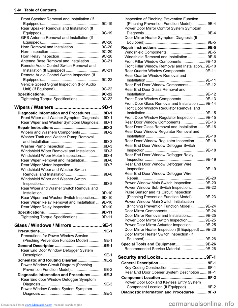
Downloaded from www.Manualslib.com manuals search engine 9-iv Table of Contents
Front Speaker Removal and Installation (If
Equipped) ........................................................9C-19
Rear Speaker Removal and Installation (If
Equipped) ........................................................9C-19
GPS Antenna Removal and Installation (If
Equipped) ........................................................9C-20
Horn Removal and Installation ..........................9C-20
Horn Inspection .................................................9C-20
Horn Relay Inspection .......................................9C-20
Antenna Base Removal and Installation ...........9C-21
Remote Audio Control Switch Removal and
Installation (If Equipped) .................................9C-21
Remote Audio Control Switch Inspection (If
Equipped) ........................................................9C-22
Vehicle Speed Signal Inspection (For Audio
Unit) (If Equipped) ...........................................9C-22
Specifications .....................................................9C-22
Tightening Torque Specifications ......................9C-22
Wipers / Washers .................................... 9D-1
Diagnostic Information and Procedures ............ 9D-1
Front Wiper and Washer Symptom Diagnosis ....9D-1
Rear Wiper and Washer Symptom Diagnosis..... 9D-1
Repair Instructions ..............................................9D-2
Wipers and Washers Components .....................9D-2
Washer Tank and Washer Pump Removal
and Installation ..................................................9D-3
Washer Pump Inspection ....................................9D-3
Windshield Wiper Removal and Installation ........9D-3
Windshield Wiper Motor Inspection.....................9D-4
Rear Wiper Removal and Installation.................. 9D-6
Rear Wiper Motor Inspection ..............................9D-7
Windshield Wiper and Washer Switch
Removal and Installation ................................... 9D-8
Windshield Wiper and Washer Switch
Inspection .......................................................... 9D-8
Rear Wiper and Washer Switch Removal and
Installation .......................................................9D-10
Rear Wiper and Washer Switch Inspection.......9D-10
Rear Wiper Relay Removal and Installation .....9D-10
Rear Wiper Relay Inspection ............................9D-10
Specifications .....................................................9D-11
Tightening Torque Specifications ......................9D-11
Glass / Windows / Mirrors .......................9E-1
Precautions........................................................... 9E-1
Precautions for Power Window Service
(Pinching Prevention Function Model) .............. 9E-1
General Description ............................................. 9E-1
Rear End Door Window Defogger System
Description ........................................................ 9E-1
Schematic and Routing Diagram ........................ 9E-2
Power Window Circuit Diagram (Pinching
Prevention Function Model) .............................. 9E-2
Diagnostic Information and Procedures ............ 9E-3
Rear End door Window Defogger Symptom
Diagnosis .......................................................... 9E-3
Power Window Control System Symptom
Diagnosis .......................................................... 9E-3Inspection of Pinching Prevention Function
(Pinching Prevention Function Model) .............. 9E-4
Power Door Mirror Control System Symptom
Diagnosis .......................................................... 9E-4
Door Mirror Heater Symptom Diagnosis (If
Equipped) .......................................................... 9E-5
Repair Instructions .............................................. 9E-5
Windshield Components ..................................... 9E-5
Windshield Removal and Installation .................. 9E-6
Front Pillar Window Components...................... 9E-10
Front Pillar Window Removal and Installation... 9E-10
Rear Quarter Window Components .................. 9E-11
Rear Quarter Window Removal and
Installation ....................................................... 9E-11
Rear End Door Window Components ............... 9E-12
Rear End Door Glass Removal and
Installation ....................................................... 9E-12
Front Door Window Components ...................... 9E-13
Front Door Glass Removal and Installation ...... 9E-14
Front Door Window Regulator Removal and
Installation ....................................................... 9E-15
Front Door Window Regulator Inspection ......... 9E-15
Rear Door Window Components ...................... 9E-16
Rear Door Glass Removal and Installation ....... 9E-16
Rear Door Window Regulator Removal and
Installation ....................................................... 9E-18
Rear Door Window Regulator Inspection .......... 9E-18
Rear End Door Window Defogger Switch
Inspection ........................................................ 9E-18
Rear End Door Window Defogger Relay
Inspection ........................................................ 9E-19
Rear End Door Window Defogger Wire
Inspection ........................................................ 9E-19
Rear End Door Window Defogger Wire
Repair.............................................................. 9E-20
Power Window Main Switch Inspection ............ 9E-20
Power Window Sub Switch Inspection .............. 9E-22
Pulse Sensor and Its Circuit Inspection
(Pinching Prevention Function Model) ............ 9E-23
Power Window Main Switch Initialization
(Pinching Prevention Function Model) ............ 9E-24
Door Mirror Components................................... 9E-24
Door Mirror Removal and Installation................ 9E-25
Power Door Mirror Switch Inspection ................ 9E-25
Power Door Mirror Actuator Inspection ............. 9E-25
Door Mirror Heater Inspection (If Equipped) ..... 9E-26
Door Mirror Heater Switch Inspection (If
Equipped) ........................................................ 9E-26
Special Tools and Equipment ........................... 9E-26
Recommended Service Material ....................... 9E-26
Security and Locks...................................9F-1
General Description ............................................. 9F-1
Key Coding Construction .................................... 9F-1
Rear End Door Opener System Description ....... 9F-1
Component Location ........................................... 9F-2
Power Door Lock and Keyless Entry System
Component Location (If Equipped) ................... 9F-2
Diagnostic Information and Procedures ............ 9F-3
Page 1169 of 1556
Downloaded from www.Manualslib.com manuals search engine Wiring Systems: 9A-2
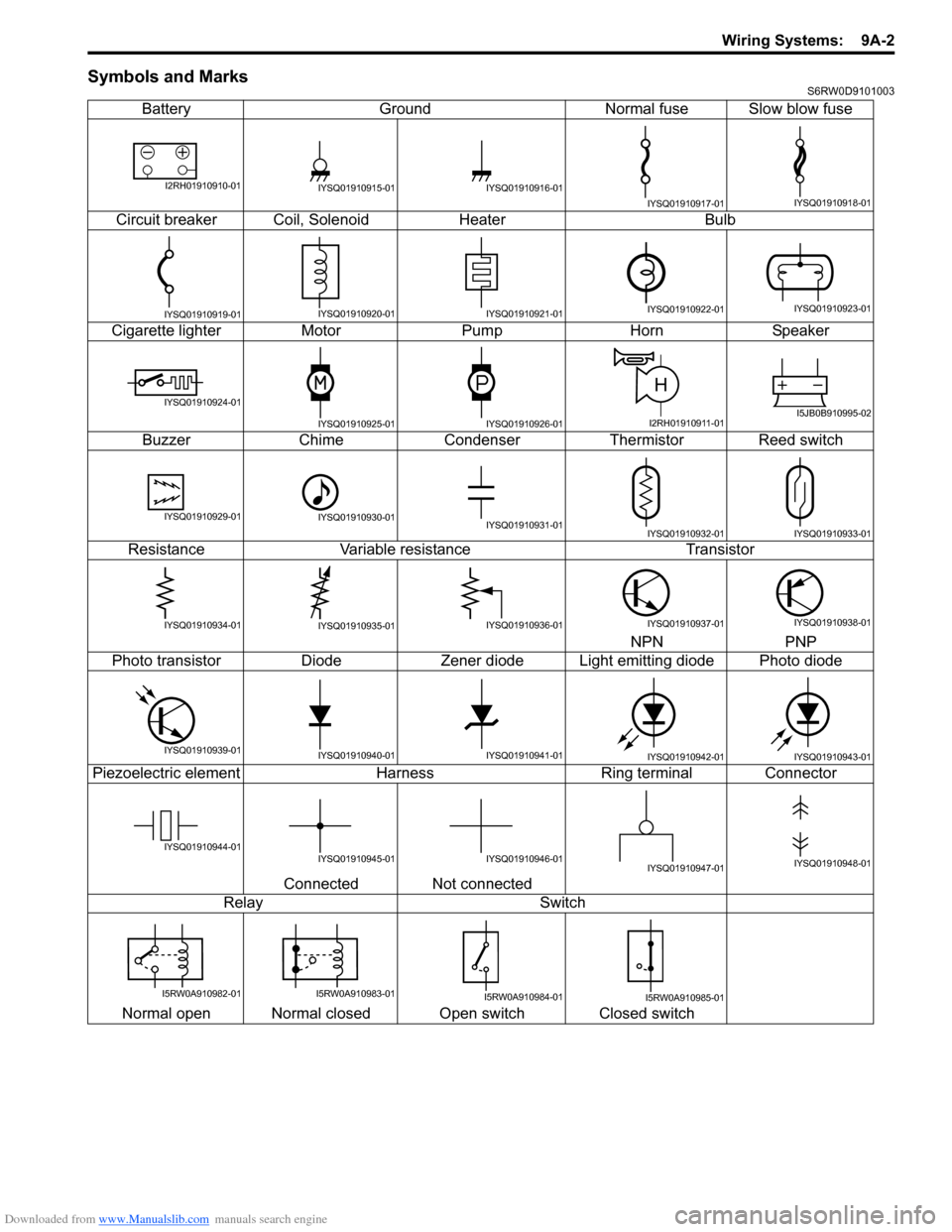
Symbols and MarksS6RW0D9101003
Battery Ground Normal fuse Slow blow fuse
Circuit breaker Coil, Solenoid Heater Bulb
Cigarette lighter Motor Pump Horn Speaker
Buzzer Chime Condenser Thermistor Reed switch
Resistance Variable resistance Transistor
NPN PNP
Photo transistor Diode Zener diode Light emitting diode Photo diode
Piezoelectric element Harness Ring terminal Connector
Connected Not connected
Relay Switch
Normal open Normal closed Open switch Closed switch
I2RH01910910-01IYSQ01910915-01IYSQ01910916-01
IYSQ01910917-01IYSQ01910918-01
IYSQ01910919-01IYSQ01910920-01IYSQ01910921-01IYSQ01910922-01IYSQ01910923-01
IYSQ01910924-01
IYSQ01910925-01IYSQ01910926-01
H
I2RH01910911-01I5JB0B910995-02
IYSQ01910929-01IYSQ01910930-01IYSQ01910931-01IYSQ01910932-01IYSQ01910933-01
IYSQ01910934-01IYSQ01910935-01IYSQ01910936-01IYSQ01910937-01IYSQ01910938-01
IYSQ01910939-01IYSQ01910940-01IYSQ01910941-01IYSQ01910942-01IYSQ01910943-01
IYSQ01910944-01IYSQ01910945-01IYSQ01910946-01IYSQ01910947-01IYSQ01910948-01
I5RW0A910982-01I5RW0A910983-01I5RW0A910984-01I5RW0A910985-01
Page 1177 of 1556
![SUZUKI SX4 2006 1.G Service Workshop Manual Downloaded from www.Manualslib.com manuals search engine Wiring Systems: 9A-10
[D]: Terminals-in-one-connector mark
[E]: Wire color
[F]: Shield wire
[G]: Ground point
[H]: “From” or “To” (Wit SUZUKI SX4 2006 1.G Service Workshop Manual Downloaded from www.Manualslib.com manuals search engine Wiring Systems: 9A-10
[D]: Terminals-in-one-connector mark
[E]: Wire color
[F]: Shield wire
[G]: Ground point
[H]: “From” or “To” (Wit](/img/20/7612/w960_7612-1176.png)
Downloaded from www.Manualslib.com manuals search engine Wiring Systems: 9A-10
[D]: Terminals-in-one-connector mark
[E]: Wire color
[F]: Shield wire
[G]: Ground point
[H]: “From” or “To” (With ID letter (s))
[I]: Specification variation
The white arrow between A and B means “or”.
[J]: “From” (With ID letter (s))
[K] “To” (With ID letter (s))
[L]: Connector code
[M]: Terminal No.
[N]: Symbol mark
[O]: “SEE” mark
Switch
BLU
BLU
GRN/BLK
GRN/REDGRN/BLK
12
GRN
GRN
C262
1
BLK
5
BLK
2 1
C40
GRN/BLK
"XX"
Solenoid FuseFuse
3
15A
Main
relay
ON OFF
1
15A
6
20A
1
Sensor 1
2
8
BRN/RED
E521
2E521
BRN/RED
RED
2
BRN/REDBRN/RED
MotorM M
655
A
B
AB5
6
1
2
56464 4-DOOR
2-DOOR
2
C71
E03
E34
O06
C31
E19
[A]
[B]
[C]
[F]
[G]
[H] [D][I] [K] [L]
E3375E341
21
43E08
ORNWHTYEL
RED
YELYEL/REDGRN/RED
4
3
YEL
BLK/RED
ORN
GRN
GRN
BA
GRN
GRN
2
XX
Cont.M
[J]
[E]
[N] [O] [M]
GBGR
Y
Y
GB
P
3
4
2
3
L50 G20
1
GR
Y
BLK
BLK
GR
I5RW0A910994-02
Page 1184 of 1556
Downloaded from www.Manualslib.com manuals search engine 9A-17 Wiring Systems:
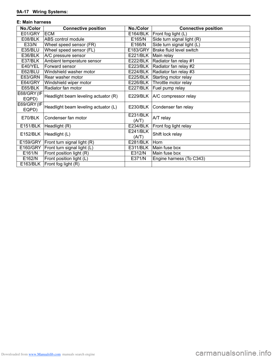
E: Main harness
No./Color Connective position No./Color Connective position
E01/GRY ECM E164/BLK Front fog light (L)
E08/BLK ABS control module E165/N Side turn signal light (R)
E33/N Wheel speed sensor (FR) E166/N Side turn signal light (L)
E35/BLU Wheel speed sensor (FL)E183/GRY Brake fluid level switch
E36/BLK A/C pressure sensor E221/BLK Main relay
E37/BLK Ambient temperature sensor E222/BLK Radiator fan relay #1
E40/YEL Forward sensor E223/BLK Radiator fan relay #2
E62/BLU Windshield washer motor E224/BLK Radiator fan relay #3
E63/GRN Rear washer motor E225/BLK Starting motor relay
E64/GRY Windshield wiper motor E226/BLK Throttle motor relay
E65/BLK Radiator fan motor E227/BLK Fuel pump relay
E68/GRY (IF
EQPD)Headlight beam leveling actuator (R) E229/BLK A/C compressor relay
E69/GRY (IF
EQPD)Headlight beam leveling actuator (L) E230/BLK Condenser fan relay
E70/BLK Condenser fan motorE231/BLK
(A/T)A/T relay
E151/BLK Headlight (R) E234/BLK Front fog light relay
E152/BLK Headlight (L)E241/BLK
(A/T)Shift lock relay
E159/GRY Front turn signal light (R) E281/BLK Horn
E160/GRY Front turn signal light (L) E311/BLK Main fuse box
E161/N Front position light (R) E312/N Main fuse box
E162/N Front position light (L) E371/N Engine harness (To C343)
E163/BLK Front fog light (R)
Page 1185 of 1556
Downloaded from www.Manualslib.com manuals search engine Wiring Systems: 9A-18
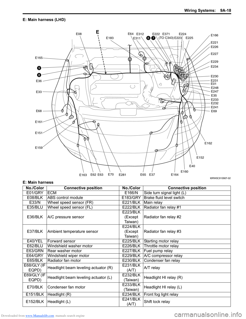
E: Main harness (LHD)
E: Main harness
E40
E33
E165
E36
E161
E68
E151
E159
E70E281E163E62E63E65E37E164
E64
E183
E08
E311
E312E222E224E225E223
E221
E371
(TO C343)E166
E227
E229
E234
E230
E01
E35
E69 E248
E247
E233
E232
E241
E162
E152
E160
E231
E226
8
9
76
E
I6RW0C910907-02
No./Color Connective position No./Color Connective position
E01/GRY ECM E166/N Side turn signal light (L)
E08/BLK ABS control module E183/GRY Brake fluid level switch
E33/N Wheel speed sensor (FR) E221/BLK Main relay
E35/BLU Wheel speed sensor (FL)E222/BLK Radiator fan relay #1
E36/BLK A/C pressure sensorE223/BLK
(Except
Ta i w a n )Radiator fan relay #2
E37/BLK Ambient temperature sensorE224/BLK
(Except
Ta i w a n )Radiator fan relay #3
E40/YEL Forward sensor E225/BLK Starting motor relay
E62/BLU Windshield washer motor E226/BLK Throttle motor relay
E63/GRN Rear washer motor E227/BLK Fuel pump relay
E64/GRY Windshield wiper motor E229/BLK A/C compressor relay
E65/BLK Radiator fan motor E230/BLK Condenser fan relay
E68/GLY (IF
EQPD)Headlight beam leveling actuator (R)E231/BLK
(A/T)A/T relay
E69/GLY (IF
EQPD)Headlight beam leveling actuator (L)E232/BLK
(Taiwan)Headlight HI relay (R)
E70/BLK Condenser fan motorE233/BLK
(Taiwan)Headlight HI relay (L)
E151/BLK Headlight (R) E234/BLK Front fog light relay
E152/BLK Headlight (L)E241/BLK
(A/T)Shift lock relay
Page 1186 of 1556

Downloaded from www.Manualslib.com manuals search engine 9A-19 Wiring Systems:
Instrument PanelS6RW0D910A003
E: Main harness, power steering wire (RHD)
E: Main harness
E: Power steering wireE159/GRY Front turn signal light (R)E247/BLK
(Taiwan)Headlight LO relay (R)
E160/GRY Front turn signal light (L)E248/BLK
(Taiwan)Headlight LO relay (L)
E161/N Front position light (R) E281/BLK Horn
E162/N Front position light (L) E311/BLK Main fuse box
E163/BLK Front fog light (R) E312/N Main fuse box
E164/BLK Front fog light (L) E371/N Engine harness (To C343)
E165/N Side turn signal light (R) No./Color Connective position No./Color Connective position
E12E13E11E387
(TO L371)E04E388
(TO L372)
E31E61
E377
E378
E325
E323
E324
E381
(TO G333)
E382
(TO G334)
E191E181E192
10
Power steering wire
E
I6RW0C910908-04
No./Color Connective position No./Color Connective position
E04/BLU BCM E325/N J/B
E13/BLK P/S control module E377/BLU Power steering wire (To E378)
E181/N Brake light switch E381/GRY Instrument panel harness (To G333)
E191/BLK APP (Acceleration pedal) sensor E382/BRN Instrument panel harness (To G334)
E192/N CPP (clutch pedal) cut switchE383/GRN
(IF EQPD)Instrument panel harness (To G335)
E323/BRN J/B E387/N Floor harness (To L371)
E324/N J/B E388/YEL Floor harness (To L372)
No./Color Connective position No./Color Connective position
E11/BLK P/S control module E61/GRY P/S motor
E12/BLU P/S control module E378/BLU Main harness (To E377)
E31/GRY Torque sensor
Page 1201 of 1556
Downloaded from www.Manualslib.com manuals search engine Wiring Systems: 9A-34
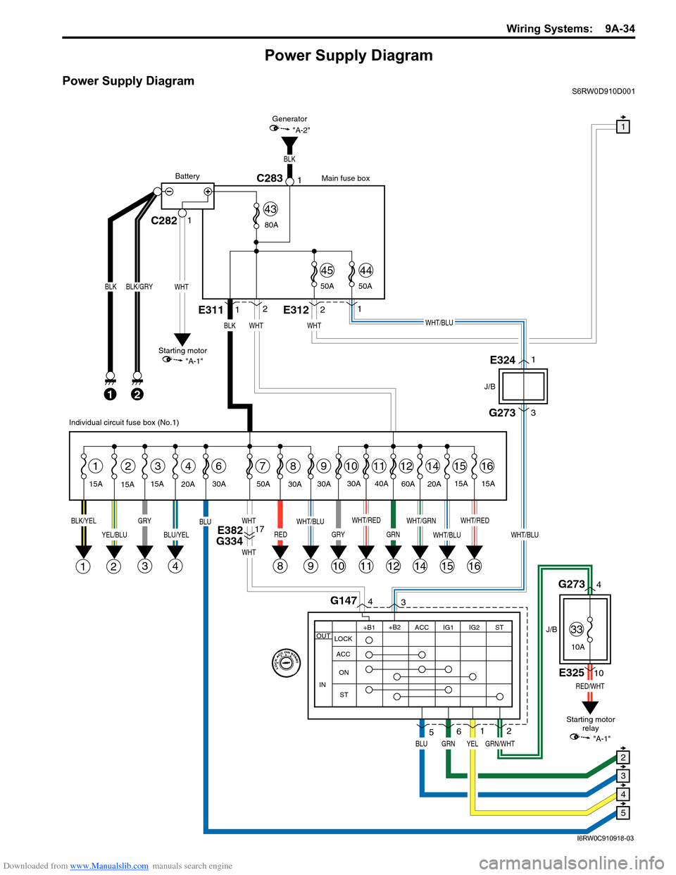
Power Supply Diagram
Power Supply DiagramS6RW0D910D001
G273
J/B
J/B
3
WHT/BLU
GRN/WHT
RED/WHT
4G1473
1
2
8
BLK
21
BLK/GRY
15A
15A15A
2314678
1E3112
WHT
1112141516
BLK/YELGRY
3
YEL/BLU
21
BLU/YEL
4
BLU
RED
WHT
WHT
WHT/RED
11
WHT/GRN
14
WHT/BLU
1516
WHT/RED
GRN
12
30A
9
WHT/BLU
9
30A
20A30A 50A40A
60A
20A15A
15A
BLK
2E3121
WHT/BLU
C282C28311
WHT
BLK
Main fuse box
Starting motor
"A-1"Generator
"A-2"
Battery
80A
50A 50A
4544
43
E3241
E32510
G2734
WHT
YEL
Individual circuit fuse box (No.1)
+B1
LOCK
ACC
ON
STACC IG1 IG2STOUT
IN
+B2
6
GRNBLU
5
Starting motor
relay
10
GRY
10
30A
E382
G33417
1
5
4
3
2
"A-1"
33
10A
I6RW0C910918-03