relay SUZUKI SX4 2006 1.G Service Manual Online
[x] Cancel search | Manufacturer: SUZUKI, Model Year: 2006, Model line: SX4, Model: SUZUKI SX4 2006 1.GPages: 1556, PDF Size: 37.31 MB
Page 658 of 1556
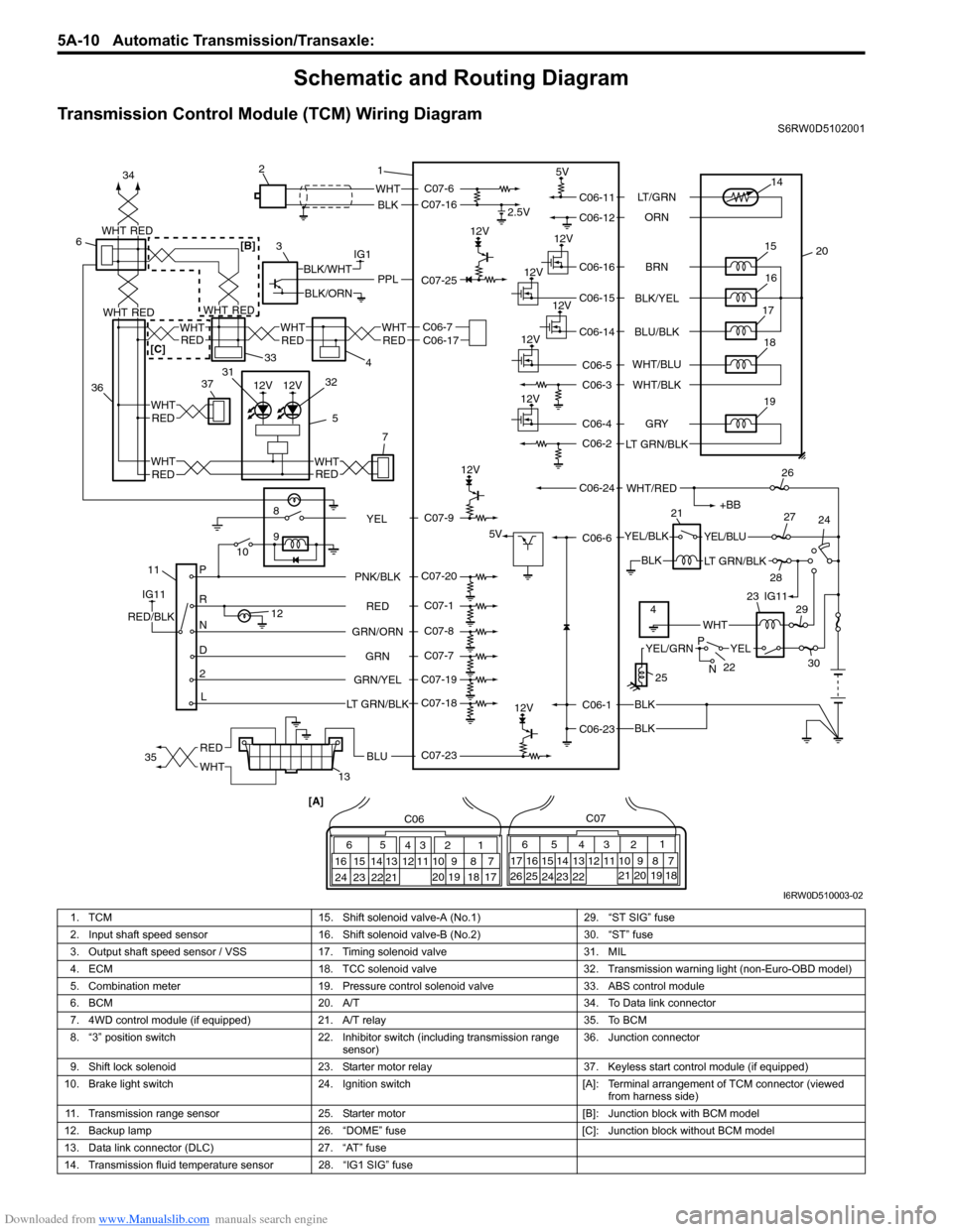
Downloaded from www.Manualslib.com manuals search engine 5A-10 Automatic Transmission/Transaxle:
Schematic and Routing Diagram
Transmission Control Module (TCM) Wiring DiagramS6RW0D5102001
12V
12V
12V
IG1
118
9
10
P
R
N
D
2
L12
2.5V
5V
12V
5V
12V
12V
12V
WHT
BLK
BLK
BLK
BLK
PPLBLK/WHT
BLK/ORN
IG11
RED/BLK
YEL/BLKYEL/BLU
LT GRN/BLK
+BB
WHT/RED
14
20 15
16
17
19
12V18
1 2
3
132126
24 27
28
29
30
65
16 15 14 13 12 1143
24 23 212210 9 8 721
19 20 18 17 C06
17 16
26 2515 14 65 342
13 12
23 22 2411 10 9
21 20 1987
18 1 C07
[A]
22
25
YELYEL/GRN
WHT
P
N
BRN LT/GRN
ORN
BLK/YEL
BLU/BLK
GRY
LT GRN/BLKWHT/BLU
WHT/BLK
C06-11
C06-12
C06-16
C06-15
C06-14
C06-4
C06-2
C06-1
C06-23C06-6 C06-24C06-5
C06-3
RED
GRN GRN/ORNPNK/BLK
GRN/YEL
LT GRN/BLKC07-6
C07-16
C07-23 C07-25
C07-20
C07-1
C07-8
C07-7
C07-19
C07-18
4IG11 23
C07-9
YEL
RED
WHTBLU35 34
3637
5REDWHT
7
WHT
RED
33
4
6
C06-7C06-17WHT
REDREDWHT
WHT
12V12V
WHTRED
WHTREDREDWHT
31
32
RED
WHTRED[B]
[C]
I6RW0D510003-02
1. TCM 15. Shift solenoid valve-A (No.1) 29. “ST SIG” fuse
2. Input shaft speed sensor 16. Shift solenoid valve-B (No.2) 30. “ST” fuse
3. Output shaft speed sensor / VSS 17. Timing solenoid valve 31. MIL
4. ECM 18. TCC solenoid valve 32. Transmission warning light (non-Euro-OBD model)
5. Combination meter 19. Pressure control solenoid valve 33. ABS control module
6. BCM 20. A/T 34. To Data link connector
7. 4WD control module (if equipped) 21. A/T relay 35. To BCM
8. “3” position switch 22. Inhibitor switch (including transmission range
sensor)36. Junction connector
9. Shift lock solenoid 23. Starter motor relay 37. Keyless start control module (if equipped)
10. Brake light switch 24. Ignition switch [A]: Terminal arrangement of TCM connector (viewed
from harness side)
11. Transmission range sensor 25. Starter motor [B]: Junction block with BCM model
12. Backup lamp 26. “DOME” fuse [C]: Junction block without BCM model
13. Data link connector (DLC) 27. “AT” fuse
14. Transmission fluid temperature sensor 28. “IG1 SIG” fuse
Page 662 of 1556
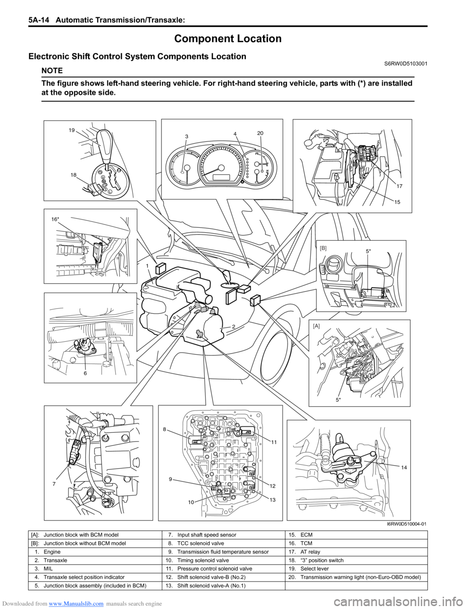
Downloaded from www.Manualslib.com manuals search engine 5A-14 Automatic Transmission/Transaxle:
Component Location
Electronic Shift Control System Components LocationS6RW0D5103001
NOTE
The figure shows left-hand steering vehicle. For right-hand steering vehicle, parts with (*) are installed
at the opposite side.
5*
17
15
1
2
8
9
1011
12
13
16*18 19
14
7
6
3420
[B]
[A]5*
I6RW0D510004-01
[A]: Junction block with BCM model 7. Input shaft speed sensor 15. ECM
[B]: Junction block without BCM model 8. TCC solenoid valve 16. TCM
1. Engine 9. Transmission fluid temperature sensor 17. AT relay
2. Transaxle 10. Timing solenoid valve 18. “3” position switch
3. MIL 11. Pressure control solenoid valve 19. Select lever
4. Transaxle select position indicator 12. Shift solenoid valve-B (No.2) 20. Transmission warning light (non-Euro-OBD model)
5. Junction block assembly (included in BCM) 13. Shift solenoid valve-A (No.1)
Page 728 of 1556

Downloaded from www.Manualslib.com manuals search engine 5A-80 Automatic Transmission/Transaxle:
Reference waveform No. 5
Output shaft speed sensor (VSS) signal at vehicle speed
60 km/h (37 mile/h).
TCM Power and Ground Circuit CheckS6RW0D5104045
Wiring DiagramMeasurement
terminalCH1: “C07-25” to “C06-1”
Oscilloscope
settingCH1: 5 V/DIV
TIME: 20 ms/DIV
Measurement
condition• After warmed up to normal
operating temperature
• Drive vehicle at 60 km/h (37
mile/h).
I3RM0B510028-01
BLK
BLK
BLK
C06-1
C06-23
C06-6YEL/BLKYEL/BLU
LT GRN/BLK
+BB
C06-24WHT/RED1
23
6
24 231
C06C07
[A]
I6RW0B510019-01
1. TCM 3. Ignition switch
2. A/T relay [A]: Terminal arrangement of TCM connector (viewed from harness side)
Page 729 of 1556

Downloaded from www.Manualslib.com manuals search engine Automatic Transmission/Transaxle: 5A-81
Troubleshooting
Brake Interlock System InspectionS6RW0D5104046
1) Check that select lever cannot be moved to any
other range from “P” range position when ignition
switch key is at ACC position, at LOCK position or it
is removed from keyhole of ignition switch, or brake
pedal is not depressed.2) Shift select lever to “P” range position, check for the
following.
• Ignition key can be turned between LOCK and
ACC positions back and forth and also it can be
removed from ignition switch. Step Action Yes No
1Check TCM back-up power circuit
1) Disconnect TCM connector with ignition switch OFF.
2) Check for proper connection to TCM at “C06-24”
terminal.
3) If OK, check voltage at terminal “C06-24” of
disconnected TCM connector.
Is it 10 – 14 V?Go to Step 2. “WHT/RED” circuit open
or shorted to ground.
2Check TCM power circuit
1) Disconnect TCM connector with ignition switch OFF.
2) Check for proper connection to TCM at “C06-6” terminal.
3) If OK, turn ignition switch ON and check voltage at
terminal “C06-6” of disconnected TCM connector.
Is it 10 – 14 V?Go to Step 4. Go to Step 3.
3Check A/T relay operation
1) Check A/T relay operation referring to “A/T Relay
Inspection”.
Is check result satisfactory?“YEL/BLK”, “YEL/BLU”,
“LT GRN/BLK” or “BLK”
circuit for power supply
open.Replace A/T relay.
4Check TCM ground circuit
1) Turn ignition switch OFF.
2) With TCM connectors disconnected, check for proper
connection to TCM at “C06-1” / “C06-23” terminal.
3) If OK, check resistance between “C06-1” / “C06-23”
terminal of disconnected TCM connector and body
ground.
Is continuity indicated?TCM power and ground
circuits are in good
condition.“BLK” circuit for TCM
ground open.
I4RS0A510047-01
I4RS0A510048-01
Page 745 of 1556
Downloaded from www.Manualslib.com manuals search engine Automatic Transmission/Transaxle: 5A-97
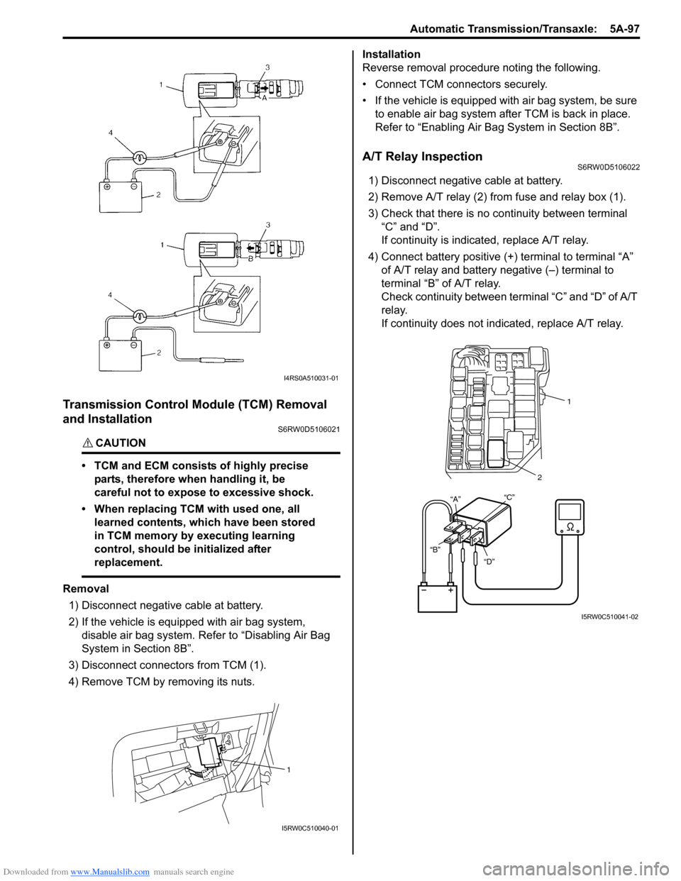
Transmission Control Module (TCM) Removal
and Installation
S6RW0D5106021
CAUTION!
• TCM and ECM consists of highly precise
parts, therefore when handling it, be
careful not to expose to excessive shock.
• When replacing TCM with used one, all
learned contents, which have been stored
in TCM memory by executing learning
control, should be initialized after
replacement.
Removal
1) Disconnect negative cable at battery.
2) If the vehicle is equipped with air bag system,
disable air bag system. Refer to “Disabling Air Bag
System in Section 8B”.
3) Disconnect connectors from TCM (1).
4) Remove TCM by removing its nuts.Installation
Reverse removal procedure noting the following.
• Connect TCM connectors securely.
• If the vehicle is equipped with air bag system, be sure
to enable air bag system after TCM is back in place.
Refer to “Enabling Air Bag System in Section 8B”.
A/T Relay InspectionS6RW0D5106022
1) Disconnect negative cable at battery.
2) Remove A/T relay (2) from fuse and relay box (1).
3) Check that there is no continuity between terminal
“C” and “D”.
If continuity is indicated, replace A/T relay.
4) Connect battery positive (+) terminal to terminal “A”
of A/T relay and battery negative (–) terminal to
terminal “B” of A/T relay.
Check continuity between terminal “C” and “D” of A/T
relay.
If continuity does not indicated, replace A/T relay.
I4RS0A510031-01
1
I5RW0C510040-01
“D” “B”“C”21
“A”
I5RW0C510041-02
Page 925 of 1556
Downloaded from www.Manualslib.com manuals search engine Table of Contents 7- i
7
Section 7
CONTENTS
HVAC
Precautions ................................................. 7-1
Precautions............................................................. 7-1
Precautions on HVAC ........................................... 7-1
Heater and Ventilation............................. 7A-1
General Description ............................................. 7A-1
Heater and Ventilation Construction ................... 7A-1
Schematic and Routing Diagram ........................ 7A-2
Heater and Ventilation Wiring Circuit Diagram .... 7A-2
Component Location ........................................... 7A-2
Electronic Control System Components
Location ............................................................ 7A-2
Diagnostic Information and Procedures ............ 7A-3
Heater and Ventilation Symptom Diagnosis........ 7A-3
Repair Instructions .............................................. 7A-4
HVAC Unit Components ..................................... 7A-4
HVAC Unit Removal and Installation (Non-A/
C) ...................................................................... 7A-4
Blower Motor Removal and Installation............... 7A-4
Blower Motor Inspection ..................................... 7A-4
Blower Motor Resistor Removal and
Installation ......................................................... 7A-5
Blower Motor Resistor Inspection ....................... 7A-5
Blower Motor Relay Inspection ........................... 7A-6
HVAC Control Unit Components ......................... 7A-6
HVAC Control Unit Removal and Installation ...... 7A-7
Blower Speed Selector Inspection ...................... 7A-9
Air Intake Selector Inspection ............................. 7A-9
Air Intake Control Actuator Removal and
Installation ......................................................... 7A-9
Air Intake Control Actuator Inspection .............. 7A-10
Center Ventilation Louver Removal and
Installation ....................................................... 7A-11
Side Ventilation Louver Removal and
Installation ....................................................... 7A-11
Rear Duct Removal and Installation (If
Equipped)........................................................ 7A-12
HVAC Air Filter Removal and Installation (If
Equipped)........................................................ 7A-12
HVAC Air Filter Inspection (If Equipped) ........... 7A-12
Air Conditioning System......................... 7B-1
Manual Type ............................................................ 7B-1
Precautions........................................................... 7B-1A/C System Caution ............................................ 7B-1
Precautions on Servicing A/C System ................ 7B-1
General Description .............................................7B-2
Sub-Cool A/C System Description ...................... 7B-2
Manual A/C Electronic Input Output Table .......... 7B-3
A/C Operation Description at ECM ..................... 7B-3
Schematic and Routing Diagram ........................7B-4
A/C System Air Flow Diagram............................. 7B-4
A/C System Wiring Diagram ............................... 7B-5
Component Location ...........................................7B-6
A/C System Major Components Location ........... 7B-6
Electronic Control System Components
Location............................................................. 7B-7
Diagnostic Information and Procedures ............7B-8
A/C System Performance Inspection .................. 7B-8
Trouble Diagnosis for Abnormal Pressure ........ 7B-11
A/C System Inspection at ECM ......................... 7B-12
A/C System Symptom Diagnosis ...................... 7B-13
Abnormal Noise Symptom Diagnosis of A/C
System ............................................................ 7B-15
Repair Instructions ............................................7B-17
Operation Procedure for Refrigerant Charge .... 7B-17
Condenser Cooling Fan Removal and
Installation ....................................................... 7B-22
Condenser Cooling Fan Inspection ................... 7B-23
Condenser Assembly On-Vehicle Inspection .... 7B-23
Condenser Assembly Removal and
Installation ....................................................... 7B-23
Desiccant Removal and Installation .................. 7B-24
HVAC Unit Components ................................... 7B-25
HVAC Unit Removal and Installation ................ 7B-26
Evaporator Inspection ....................................... 7B-27
Evaporator Temperature Sensor Removal
and Installation ................................................ 7B-27
Evaporator Temperature Sensor Inspection ..... 7B-28
Expansion Valve Removal and Installation ....... 7B-28
Expansion Valve Inspection .............................. 7B-28
A/C Refrigerant Pressure Sensor and Its
Circuit Inspection............................................. 7B-29
A/C Refrigerant Pressure Sensor Removal
and Installation ................................................ 7B-29
A/C Switch Inspection ....................................... 7B-29
A/C System Relay Inspection............................ 7B-30
Compressor Drive Belt Inspection and
Adjustment ...................................................... 7B-30
Page 926 of 1556
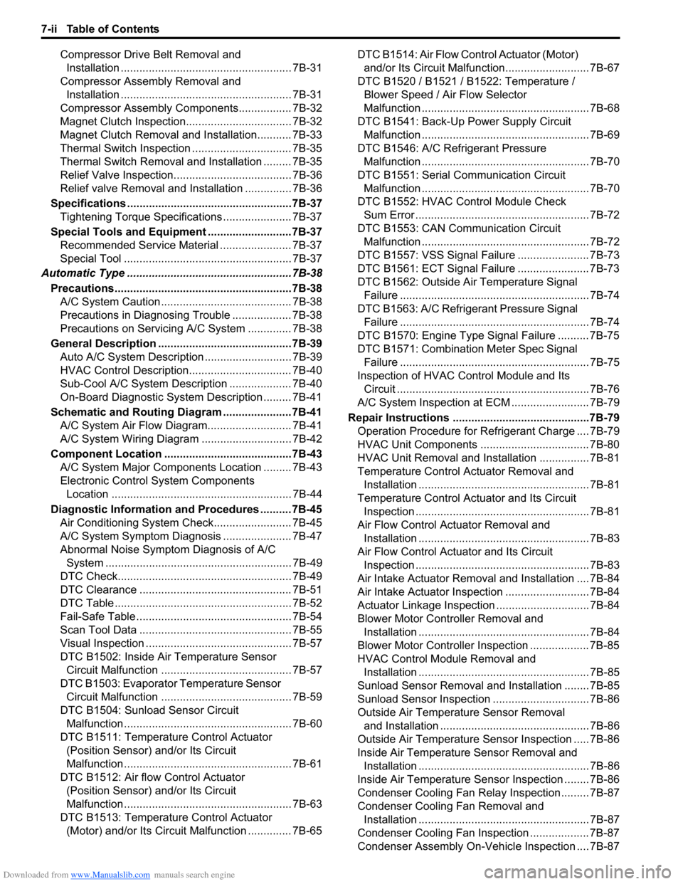
Downloaded from www.Manualslib.com manuals search engine 7-ii Table of Contents
Compressor Drive Belt Removal and
Installation ....................................................... 7B-31
Compressor Assembly Removal and
Installation ....................................................... 7B-31
Compressor Assembly Components................. 7B-32
Magnet Clutch Inspection.................................. 7B-32
Magnet Clutch Removal and Installation........... 7B-33
Thermal Switch Inspection ................................ 7B-35
Thermal Switch Removal and Installation ......... 7B-35
Relief Valve Inspection...................................... 7B-36
Relief valve Removal and Installation ............... 7B-36
Specifications .....................................................7B-37
Tightening Torque Specifications ...................... 7B-37
Special Tools and Equipment ...........................7B-37
Recommended Service Material ....................... 7B-37
Special Tool ...................................................... 7B-37
Automatic Type .....................................................7B-38
Precautions.........................................................7B-38
A/C System Caution .......................................... 7B-38
Precautions in Diagnosing Trouble ................... 7B-38
Precautions on Servicing A/C System .............. 7B-38
General Description ...........................................7B-39
Auto A/C System Description ............................ 7B-39
HVAC Control Description................................. 7B-40
Sub-Cool A/C System Description .................... 7B-40
On-Board Diagnostic System Description ......... 7B-41
Schematic and Routing Diagram ......................7B-41
A/C System Air Flow Diagram........................... 7B-41
A/C System Wiring Diagram ............................. 7B-42
Component Location .........................................7B-43
A/C System Major Components Location ......... 7B-43
Electronic Control System Components
Location .......................................................... 7B-44
Diagnostic Information and Procedures ..........7B-45
Air Conditioning System Check......................... 7B-45
A/C System Symptom Diagnosis ...................... 7B-47
Abnormal Noise Symptom Diagnosis of A/C
System ............................................................ 7B-49
DTC Check........................................................ 7B-49
DTC Clearance ................................................. 7B-51
DTC Table ......................................................... 7B-52
Fail-Safe Table .................................................. 7B-54
Scan Tool Data ................................................. 7B-55
Visual Inspection ............................................... 7B-57
DTC B1502: Inside Air Temperature Sensor
Circuit Malfunction .......................................... 7B-57
DTC B1503: Evaporator Temperature Sensor
Circuit Malfunction .......................................... 7B-59
DTC B1504: Sunload Sensor Circuit
Malfunction ...................................................... 7B-60
DTC B1511: Temperature Control Actuator
(Position Sensor) and/or Its Circuit
Malfunction ...................................................... 7B-61
DTC B1512: Air flow Control Actuator
(Position Sensor) and/or Its Circuit
Malfunction ...................................................... 7B-63
DTC B1513: Temperature Control Actuator
(Motor) and/or Its Circuit Malfunction .............. 7B-65DTC B1514: Air Flow Control Actuator (Motor)
and/or Its Circuit Malfunction........................... 7B-67
DTC B1520 / B1521 / B1522: Temperature /
Blower Speed / Air Flow Selector
Malfunction ...................................................... 7B-68
DTC B1541: Back-Up Power Supply Circuit
Malfunction ...................................................... 7B-69
DTC B1546: A/C Refrigerant Pressure
Malfunction ...................................................... 7B-70
DTC B1551: Serial Communication Circuit
Malfunction ...................................................... 7B-70
DTC B1552: HVAC Control Module Check
Sum Error ........................................................ 7B-72
DTC B1553: CAN Communication Circuit
Malfunction ...................................................... 7B-72
DTC B1557: VSS Signal Failure ....................... 7B-73
DTC B1561: ECT Signal Failure ....................... 7B-73
DTC B1562: Outside Air Temperature Signal
Failure ............................................................. 7B-74
DTC B1563: A/C Refrigerant Pressure Signal
Failure ............................................................. 7B-74
DTC B1570: Engine Type Signal Failure .......... 7B-75
DTC B1571: Combination Meter Spec Signal
Failure ............................................................. 7B-75
Inspection of HVAC Control Module and Its
Circuit .............................................................. 7B-76
A/C System Inspection at ECM ......................... 7B-79
Repair Instructions ............................................7B-79
Operation Procedure for Refrigerant Charge .... 7B-79
HVAC Unit Components ................................... 7B-80
HVAC Unit Removal and Installation ................ 7B-81
Temperature Control Actuator Removal and
Installation ....................................................... 7B-81
Temperature Control Actuator and Its Circuit
Inspection ........................................................ 7B-81
Air Flow Control Actuator Removal and
Installation ....................................................... 7B-83
Air Flow Control Actuator and Its Circuit
Inspection ........................................................ 7B-83
Air Intake Actuator Removal and Installation .... 7B-84
Air Intake Actuator Inspection ........................... 7B-84
Actuator Linkage Inspection.............................. 7B-84
Blower Motor Controller Removal and
Installation ....................................................... 7B-84
Blower Motor Controller Inspection ................... 7B-85
HVAC Control Module Removal and
Installation ....................................................... 7B-85
Sunload Sensor Removal and Installation ........ 7B-85
Sunload Sensor Inspection ............................... 7B-86
Outside Air Temperature Sensor Removal
and Installation ................................................ 7B-86
Outside Air Temperature Sensor Inspection ..... 7B-86
Inside Air Temperature Sensor Removal and
Installation ....................................................... 7B-86
Inside Air Temperature Sensor Inspection ........ 7B-86
Condenser Cooling Fan Relay Inspection......... 7B-87
Condenser Cooling Fan Removal and
Installation ....................................................... 7B-87
Condenser Cooling Fan Inspection ................... 7B-87
Condenser Assembly On-Vehicle Inspection .... 7B-87
Page 927 of 1556
Downloaded from www.Manualslib.com manuals search engine Table of Contents 7-iii
Condenser Assembly Removal and
Installation ....................................................... 7B-87
Evaporator Inspection ....................................... 7B-87
Evaporator Temperature Sensor Removal
and Installation ................................................ 7B-87
Evaporator Temperature Sensor Inspection ..... 7B-87
Expansion Valve Removal and Installation ....... 7B-87
Expansion Valve Inspection .............................. 7B-87
A/C Refrigerant Pressure Sensor and Its
Circuit Inspection ............................................ 7B-87
A/C Refrigerant Pressure Sensor Removal
and Installation ................................................ 7B-87
Compressor Relay Inspection ........................... 7B-87
Compressor Drive Belt Inspection and
Adjustment ...................................................... 7B-87Compressor Drive Belt Removal and
Installation ....................................................... 7B-87
Compressor Assembly Removal and
Installation ....................................................... 7B-87
Compressor Assembly Components................. 7B-87
Magnet Clutch Removal and Installation........... 7B-87
Magnet Clutch Inspection.................................. 7B-87
Thermal Switch Inspection ................................ 7B-87
Thermal Switch Removal and Installation ......... 7B-87
Relief Valve Inspection...................................... 7B-87
Special Tools and Equipment ...........................7B-88
Recommended Service Material ....................... 7B-88
Special Tool ...................................................... 7B-88
Page 930 of 1556
Downloaded from www.Manualslib.com manuals search engine 7A-2 Heater and Ventilation:
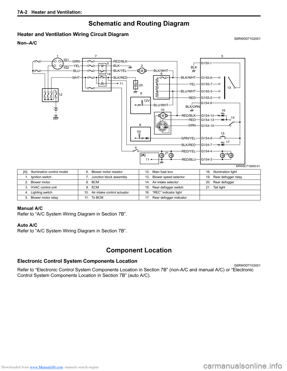
Schematic and Routing Diagram
Heater and Ventilation Wiring Circuit DiagramS6RW0D7102001
Non–A/C
Manual A/C
Refer to “A/C System Wiring Diagram in Section 7B”.
Auto A/C
Refer to “A/C System Wiring Diagram in Section 7B”.
Component Location
Electronic Control System Components LocationS6RW0D7103001
Refer to “Electronic Control System Components Location in Section 7B” (non-A/C and manual A/C) or “Electronic
Control System Components Location in Section 7B” (auto A/C).
5V
BLK
RED/BLK3
5 72
G154-3
G154-4
G154-7
G154-8
G154-10
G154-13
G155-2
G155-3
G155-7
G155-6
G155-1
G154-9
G154-14
BLK/WHT
YEL
BLU/WHT
RED
RED/BLKRED
GRN
GRN/YEL
RED/YEL
RED/BLU
BLK/ORN
46
8
BLU
YELGRN
WHT
13
1514
[A]21
BLK/RED
12V
BLK/YELBLK/WHTM
BLK
1IG1
IG2
12
BLK/RED
M 10
11
11
BLU/WHT 19
16
17
18 9 20
I6RW0C710003-01
[A]: Illumination control model 6. Blower motor resistor 12. Main fuse box 18. Illumination light
1. Ignition switch 7. Junction block assembly 13. Blower speed selector 19. Rear defogger relay
2. Blower motor 8. BCM 14. Air intake selector 20. Rear defogger
3. HVAC control unit 9. ECM 15. Rear defogger switch 21. Tail light
4. Lighting switch 10. Air intake control actuator 16. “REC” indicator light
5. Blower motor relay 11. To BCM 17. Rear defogger indicator
Page 931 of 1556
Downloaded from www.Manualslib.com manuals search engine Heater and Ventilation: 7A-3
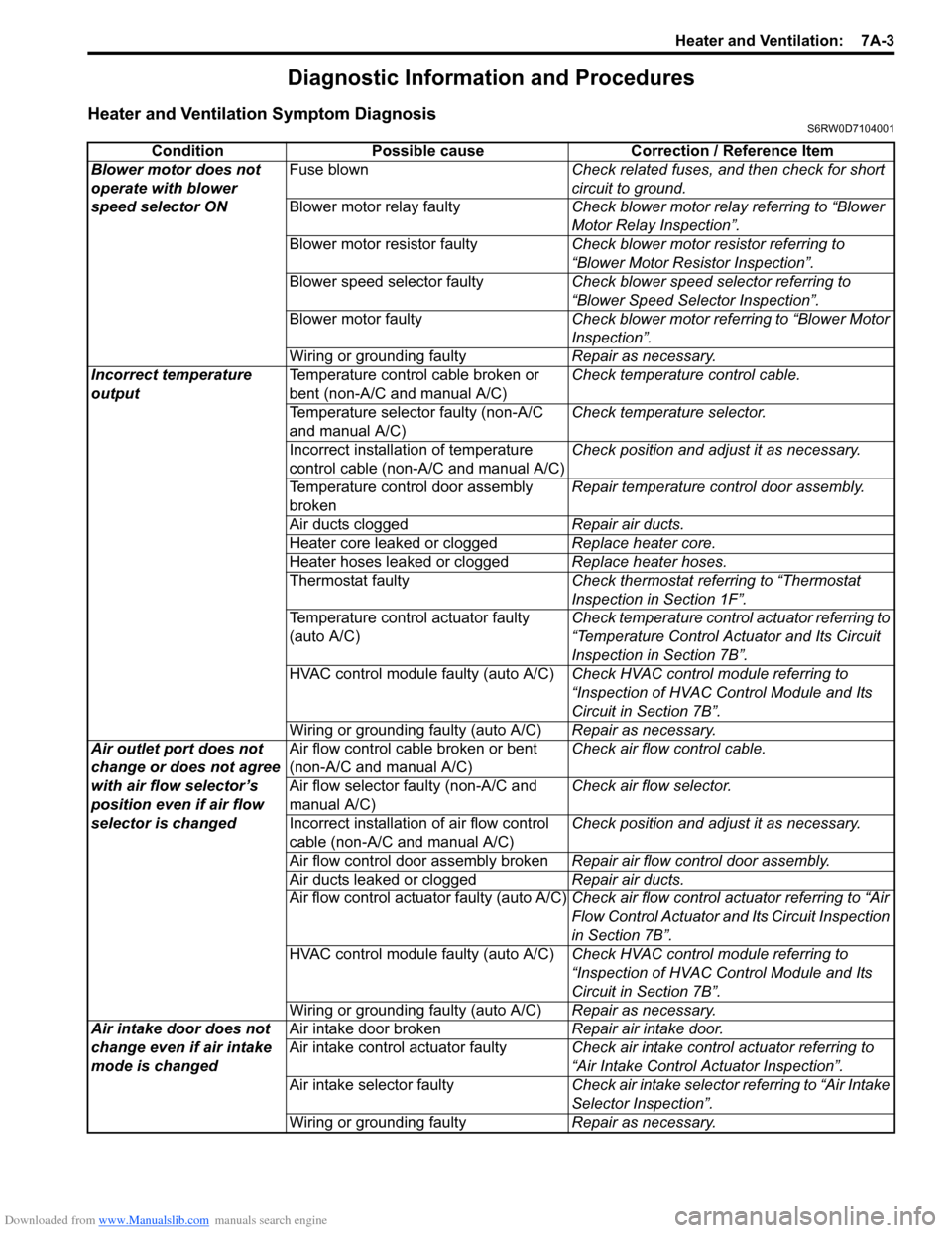
Diagnostic Information and Procedures
Heater and Ventilation Symptom DiagnosisS6RW0D7104001
Condition Possible cause Correction / Reference Item
Blower motor does not
operate with blower
speed selector ONFuse blownCheck related fuses, and then check for short
circuit to ground.
Blower motor relay faultyCheck blower motor relay referring to “Blower
Motor Relay Inspection”.
Blower motor resistor faultyCheck blower motor resistor referring to
“Blower Motor Resistor Inspection”.
Blower speed selector faultyCheck blower speed selector referring to
“Blower Speed Selector Inspection”.
Blower motor faultyCheck blower motor referring to “Blower Motor
Inspection”.
Wiring or grounding faultyRepair as necessary.
Incorrect temperature
outputTemperature control cable broken or
bent (non-A/C and manual A/C)Check temperature control cable.
Temperature selector faulty (non-A/C
and manual A/C)Check temperature selector.
Incorrect installation of temperature
control cable (non-A/C and manual A/C)Check position and adjust it as necessary.
Temperature control door assembly
brokenRepair temperature control door assembly.
Air ducts cloggedRepair air ducts.
Heater core leaked or cloggedReplace heater core.
Heater hoses leaked or cloggedReplace heater hoses.
Thermostat faultyCheck thermostat referring to “Thermostat
Inspection in Section 1F”.
Temperature control actuator faulty
(auto A/C)Check temperature control actuator referring to
“Temperature Control Actuator and Its Circuit
Inspection in Section 7B”.
HVAC control module faulty (auto A/C)Check HVAC control module referring to
“Inspection of HVAC Control Module and Its
Circuit in Section 7B”.
Wiring or grounding faulty (auto A/C)Repair as necessary.
Air outlet port does not
change or does not agree
with air flow selector’s
position even if air flow
selector is changedAir flow control cable broken or bent
(non-A/C and manual A/C)Check air flow control cable.
Air flow selector faulty (non-A/C and
manual A/C)Check air flow selector.
Incorrect installation of air flow control
cable (non-A/C and manual A/C)Check position and adjust it as necessary.
Air flow control door assembly brokenRepair air flow control door assembly.
Air ducts leaked or cloggedRepair air ducts.
Air flow control actuator faulty (auto A/C)Check air flow control actuator referring to “Air
Flow Control Actuator and Its Circuit Inspection
in Section 7B”.
HVAC control module faulty (auto A/C)Check HVAC control module referring to
“Inspection of HVAC Control Module and Its
Circuit in Section 7B”.
Wiring or grounding faulty (auto A/C)Repair as necessary.
Air intake door does not
change even if air intake
mode is changedAir intake door brokenRepair air intake door.
Air intake control actuator faultyCheck air intake control actuator referring to
“Air Intake Control Actuator Inspection”.
Air intake selector faultyCheck air intake selector referring to “Air Intake
Selector Inspection”.
Wiring or grounding faultyRepair as necessary.