SUZUKI SX4 2006 1.G Service Workshop Manual
Manufacturer: SUZUKI, Model Year: 2006, Model line: SX4, Model: SUZUKI SX4 2006 1.GPages: 1556, PDF Size: 37.31 MB
Page 1441 of 1556
Downloaded from www.Manualslib.com manuals search engine Hood / Fenders / Doors: 9J-5
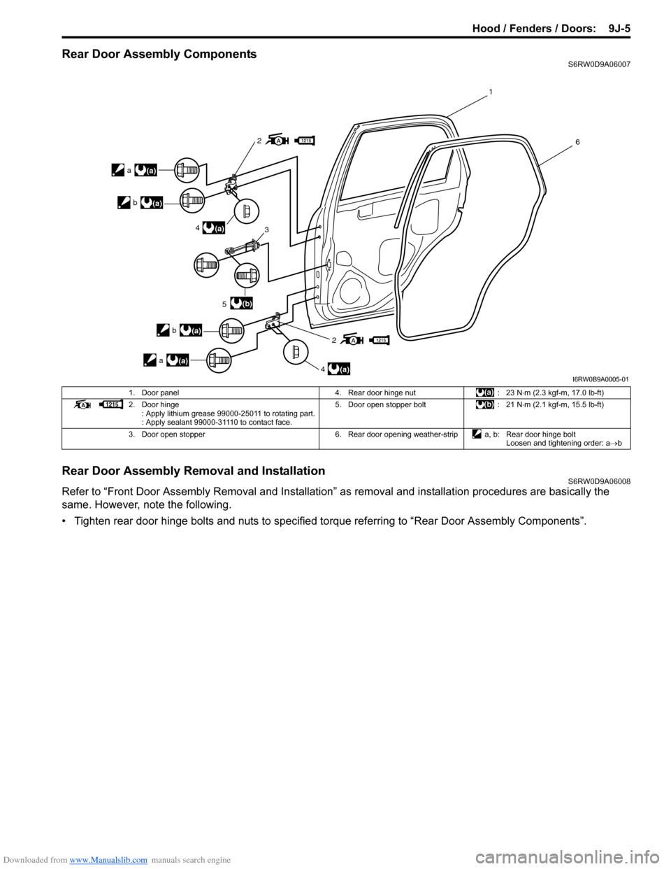
Rear Door Assembly ComponentsS6RW0D9A06007
Rear Door Assembly Removal and InstallationS6RW0D9A06008
Refer to “Front Door Assembly Removal and Installation” as removal and installation procedures are basically the
same. However, note the following.
• Tighten rear door hinge bolts and nuts to specified torque referring to “Rear Door Assembly Components”.
2
2
4
5
4 3
1
6
(a)
(a)
(b)
a(a) b
(a)
a(a)
b
(a)
I6RW0B9A0005-01
1. Door panel 4. Rear door hinge nut : 23 N⋅m (2.3 kgf-m, 17.0 lb-ft)
2. Door hinge
: Apply lithium grease 99000-25011 to rotating part.
: Apply sealant 99000-31110 to contact face.5. Door open stopper bolt : 21 N⋅m (2.1 kgf-m, 15.5 lb-ft)
3. Door open stopper 6. Rear door opening weather-strip a, b: Rear door hinge bolt
Loosen and tightening order: a→b
Page 1442 of 1556
Downloaded from www.Manualslib.com manuals search engine 9J-6 Hood / Fenders / Doors:
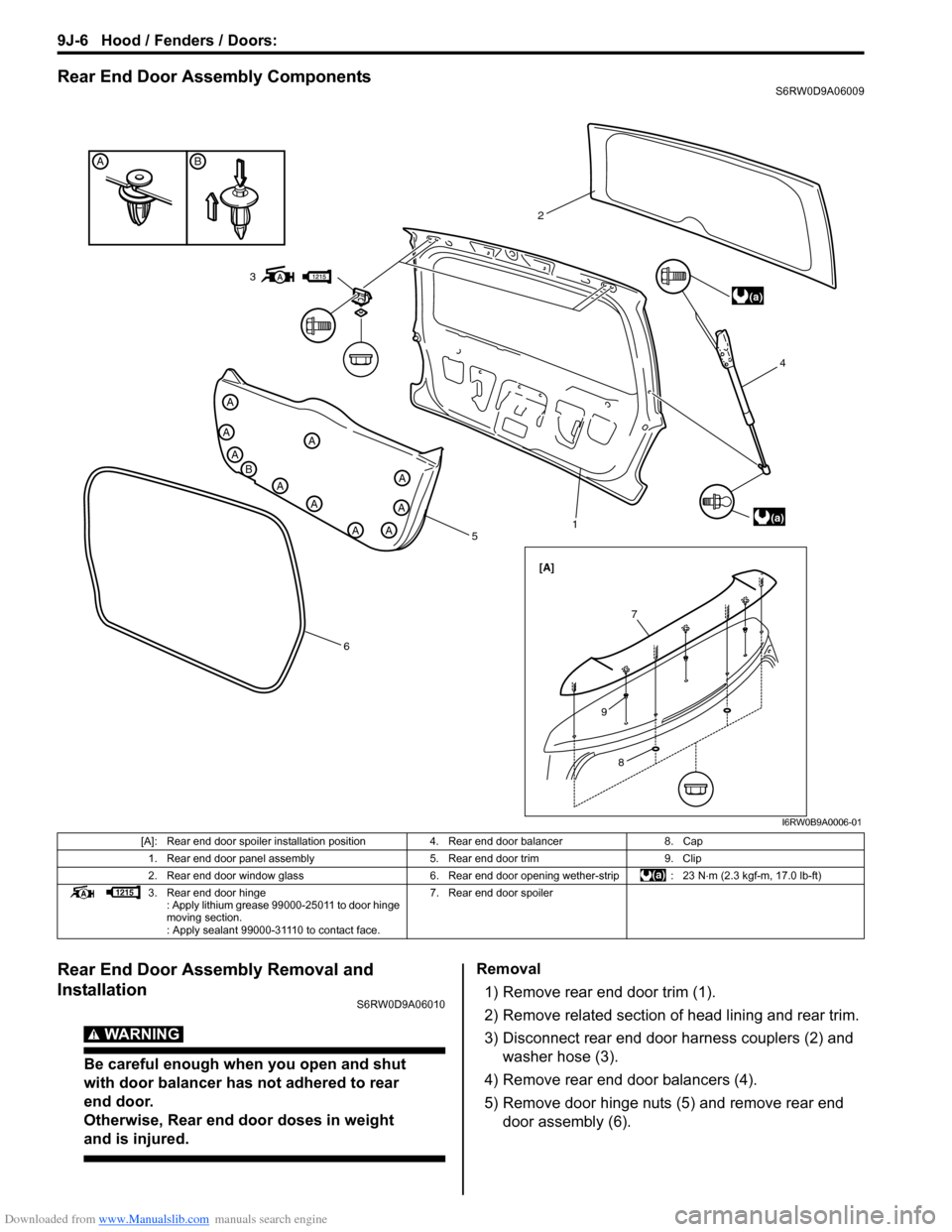
Rear End Door Assembly ComponentsS6RW0D9A06009
Rear End Door Assembly Removal and
Installation
S6RW0D9A06010
WARNING!
Be careful enough when you open and shut
with door balancer has not adhered to rear
end door.
Otherwise, Rear end door doses in weight
and is injured.
Removal
1) Remove rear end door trim (1).
2) Remove related section of head lining and rear trim.
3) Disconnect rear end door harness couplers (2) and
washer hose (3).
4) Remove rear end door balancers (4).
5) Remove door hinge nuts (5) and remove rear end
door assembly (6).
BA
A
B
A
A
A
A
A
AA
A
A
5
614 2
(a)
(a)
[A]
3
7
8
9
I6RW0B9A0006-01
[A]: Rear end door spoiler installation position 4. Rear end door balancer 8. Cap
1. Rear end door panel assembly 5. Rear end door trim 9. Clip
2. Rear end door window glass 6. Rear end door opening wether-strip : 23 N⋅m (2.3 kgf-m, 17.0 lb-ft)
3. Rear end door hinge
: Apply lithium grease 99000-25011 to door hinge
moving section.
: Apply sealant 99000-31110 to contact face.7. Rear end door spoiler
Page 1443 of 1556
Downloaded from www.Manualslib.com manuals search engine Hood / Fenders / Doors: 9J-7
WARNING!
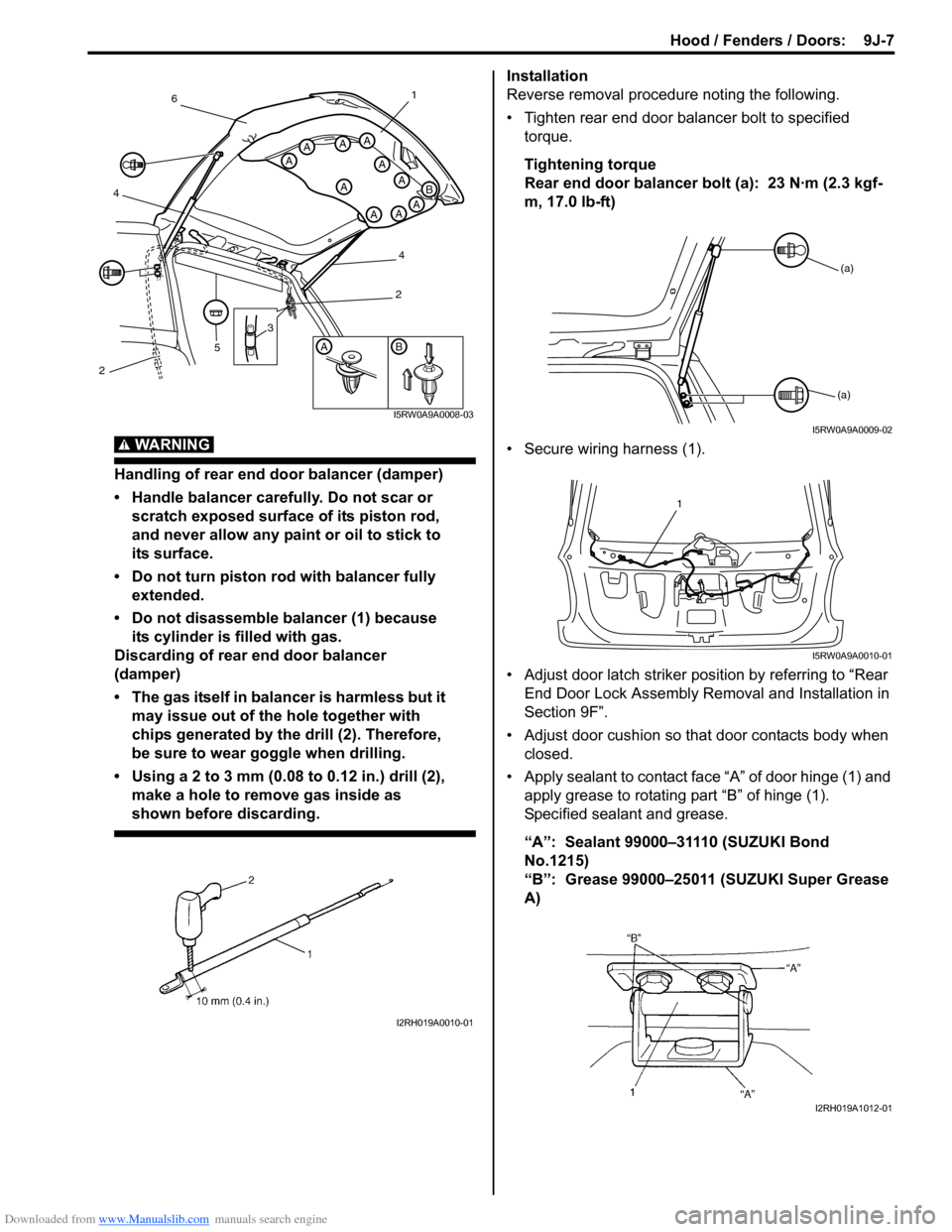
Handling of rear end door balancer (damper)
• Handle balancer carefully. Do not scar or
scratch exposed surface of its piston rod,
and never allow any paint or oil to stick to
its surface.
• Do not turn piston rod with balancer fully
extended.
• Do not disassemble balancer (1) because
its cylinder is filled with gas.
Discarding of rear end door balancer
(damper)
• The gas itself in balancer is harmless but it
may issue out of the hole together with
chips generated by the drill (2). Therefore,
be sure to wear goggle when drilling.
• Using a 2 to 3 mm (0.08 to 0.12 in.) drill (2),
make a hole to remove gas inside as
shown before discarding.
Installation
Reverse removal procedure noting the following.
• Tighten rear end door balancer bolt to specified
torque.
Tightening torque
Rear end door balancer bolt (a): 23 N·m (2.3 kgf-
m, 17.0 lb-ft)
• Secure wiring harness (1).
• Adjust door latch striker position by referring to “Rear
End Door Lock Assembly Removal and Installation in
Section 9F”.
• Adjust door cushion so that door contacts body when
closed.
• Apply sealant to contact face “A” of door hinge (1) and
apply grease to rotating part “B” of hinge (1).
Specified sealant and grease.
“A”: Sealant 99000–31110 (SUZUKI Bond
No.1215)
“B”: Grease 99000–25011 (SUZUKI Super Grease
A)
AB
A
A
A
A
AAA
AAA
B
3
5
461
4
2
2
I5RW0A9A0008-03
I2RH019A0010-01
(a)
(a)
I5RW0A9A0009-02
1
I5RW0A9A0010-01
I2RH019A1012-01
Page 1444 of 1556
Downloaded from www.Manualslib.com manuals search engine 9J-8 Hood / Fenders / Doors:
Specifications
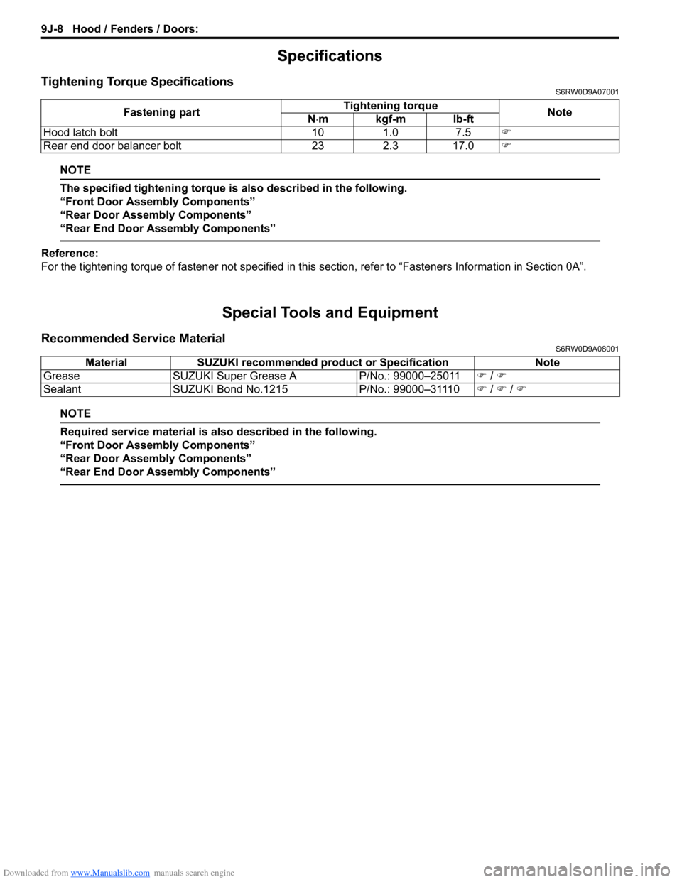
Tightening Torque SpecificationsS6RW0D9A07001
NOTE
The specified tightening torque is also described in the following.
“Front Door Assembly Components”
“Rear Door Assembly Components”
“Rear End Door Assembly Components”
Reference:
For the tightening torque of fastener not specified in this section, refer to “Fasteners Information in Section 0A”.
Special Tools and Equipment
Recommended Service MaterialS6RW0D9A08001
NOTE
Required service material is also described in the following.
“Front Door Assembly Components”
“Rear Door Assembly Components”
“Rear End Door Assembly Components”
Fastening partTightening torque
Note
N⋅mkgf-mlb-ft
Hood latch bolt 10 1.0 7.5�)
Rear end door balancer bolt 23 2.3 17.0�)
Material SUZUKI recommended product or Specification Note
Grease SUZUKI Super Grease A P/No.: 99000–25011�) / �)
Sealant SUZUKI Bond No.1215 P/No.: 99000–31110�) / �) / �)
Page 1445 of 1556
Downloaded from www.Manualslib.com manuals search engine Body Structure: 9K-1
Body, Cab and Accessories
Body Structure
Repair Instructions
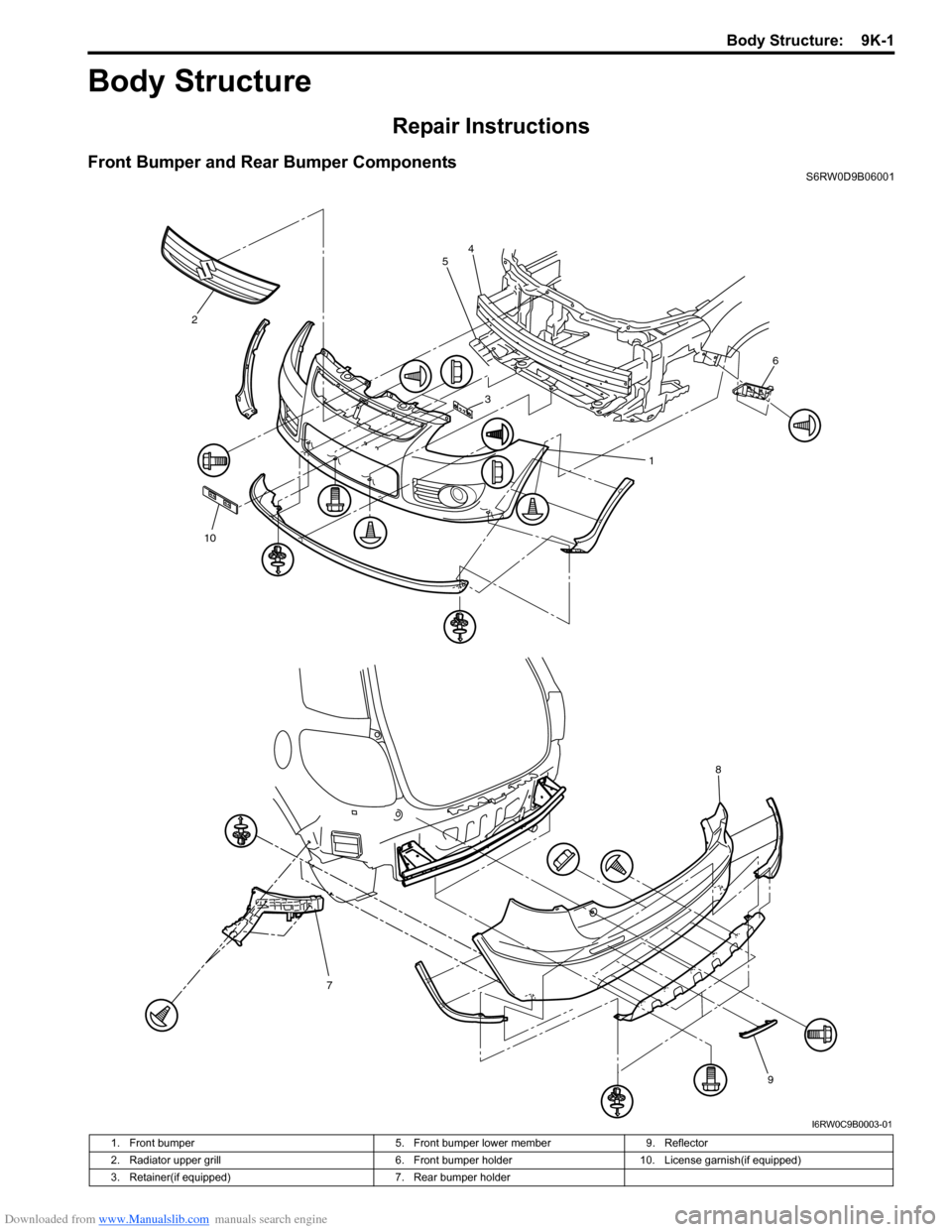
Front Bumper and Rear Bumper ComponentsS6RW0D9B06001
1 24
5
6
3
78
9
10
I6RW0C9B0003-01
1. Front bumper 5. Front bumper lower member 9. Reflector
2. Radiator upper grill 6. Front bumper holder 10. License garnish(if equipped)
3. Retainer(if equipped) 7. Rear bumper holder
Page 1446 of 1556
Downloaded from www.Manualslib.com manuals search engine 9K-2 Body Structure:
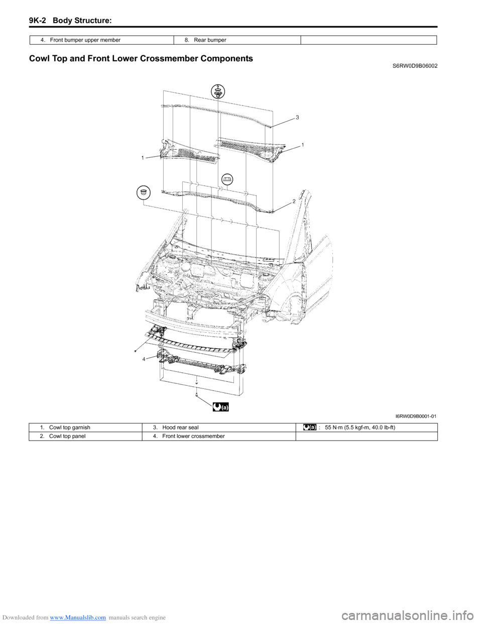
Cowl Top and Front Lower Crossmember ComponentsS6RW0D9B06002 4. Front bumper upper member 8. Rear bumper
I6RW0D9B0001-01
1. Cowl top garnish 3. Hood rear seal : 55 N⋅m (5.5 kgf-m, 40.0 lb-ft)
2. Cowl top panel 4. Front lower crossmember
Page 1447 of 1556
Downloaded from www.Manualslib.com manuals search engine Body Structure: 9K-3
Specifications
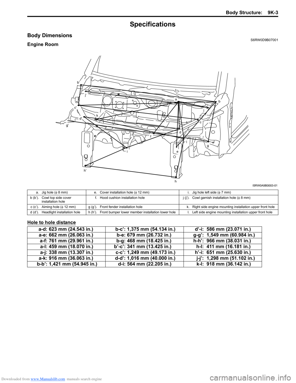
Body DimensionsS6RW0D9B07001
Engine Room
Hole to hole distance
ab
c
d
e
f
g
h
i
j
l
k
b'
c'
d'
g'
h'
j'
I5RW0A9B0003-01
a. Jig hole (φ 8 mm) e. Cover installation hole (φ 12 mm) i. Jig hole left side (φ 7 mm)
b (b’). Cowl top side cover
installation holef. Hood cushion installation hole j (j’). Cowl garnish installation hole (φ 8 mm)
c (c’). Aiming hole (φ 12 mm) g (g’). Front fender installation hole k. Right side engine mounting installation upper front hole
d (d’). Headlight installation hole h (h’). Front bumper lower member installation lower hole l. Left side engine mounting installation upper front hole
a-d: 623 mm (24.543 in.) b-c’: 1,375 mm (54.134 in.) d’-i: 586 mm (23.071 in.)
a-e: 662 mm (26.063 in.) b-e: 679 mm (26.732 in.) g-g’: 1,549 mm (60.984 in.)
a-f: 761 mm (29.961 in.) b-g: 468 mm (18.425 in.) h-h’: 966 mm (38.031 in.)
a-l: 459 mm (18.070 in.) b’-c’: 341 mm (13.425 in.) h-l: 411 mm (16.181 in.)
a-j: 338 mm (13.307 in.) c-c’: 1,249 mm (49.173 in.) h’-i: 651 mm (25.630 in.)
a-k: 916 mm (36.063 in.) d-d’: 1,016 mm (40.000 in.) j-j’: 1,298 mm (51.102 in.)
b-b’: 1,421 mm (54.945 in.) d-i: 564 mm (22.205 in.) k-l: 918 mm (36.142 in.)
Page 1448 of 1556
Downloaded from www.Manualslib.com manuals search engine 9K-4 Body Structure:
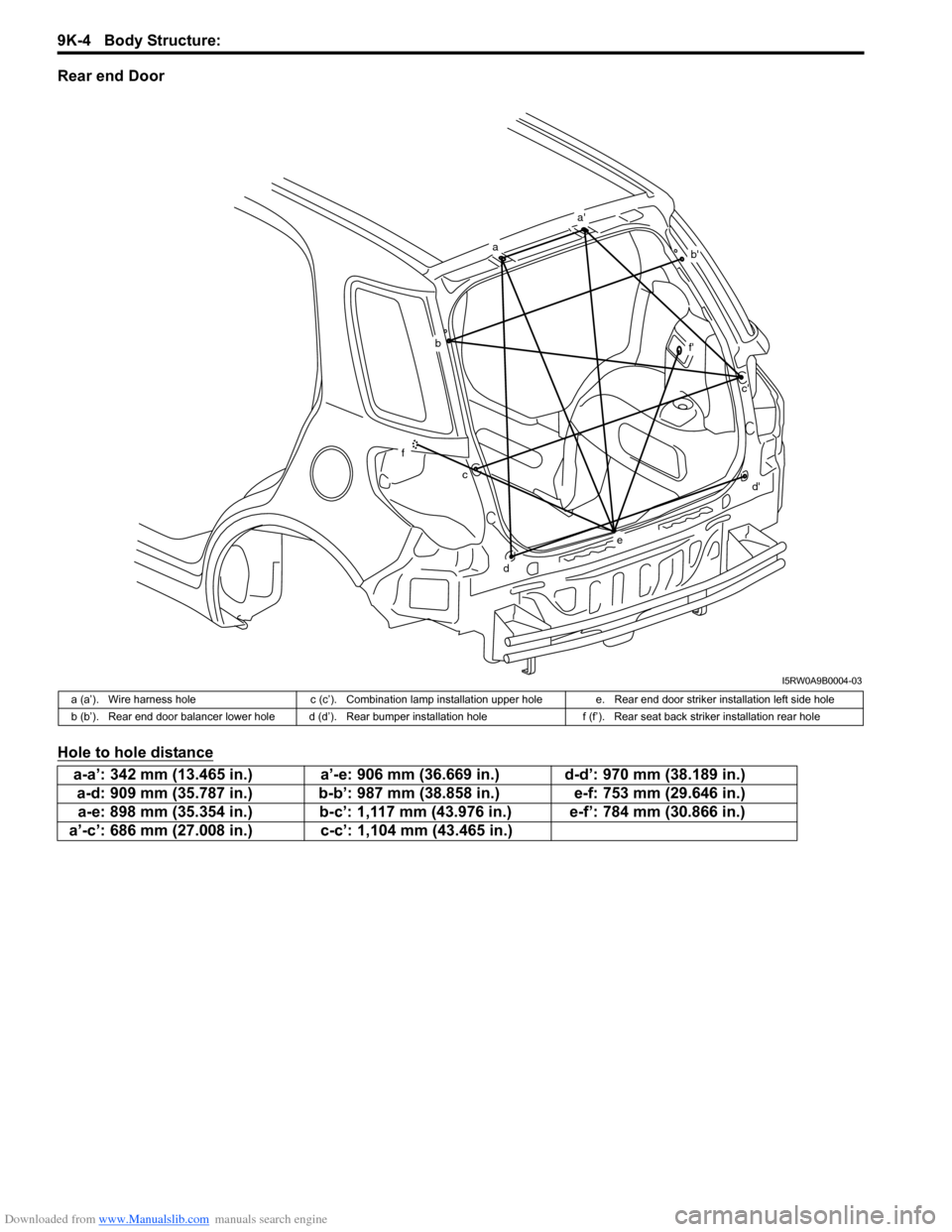
Rear end Door
Hole to hole distance
a
a'
b'
b
f
cc'
f'
d
d'
e
I5RW0A9B0004-03
a (a’). Wire harness hole c (c’). Combination lamp installation upper hole e. Rear end door striker installation left side hole
b (b’). Rear end door balancer lower hole d (d’). Rear bumper installation hole f (f’). Rear seat back striker installation rear hole
a-a’: 342 mm (13.465 in.) a’-e: 906 mm (36.669 in.) d-d’: 970 mm (38.189 in.)
a-d: 909 mm (35.787 in.) b-b’: 987 mm (38.858 in.) e-f: 753 mm (29.646 in.)
a-e: 898 mm (35.354 in.) b-c’: 1,117 mm (43.976 in.) e-f’: 784 mm (30.866 in.)
a’-c’: 686 mm (27.008 in.) c-c’: 1,104 mm (43.465 in.)
Page 1449 of 1556
Downloaded from www.Manualslib.com manuals search engine Body Structure: 9K-5
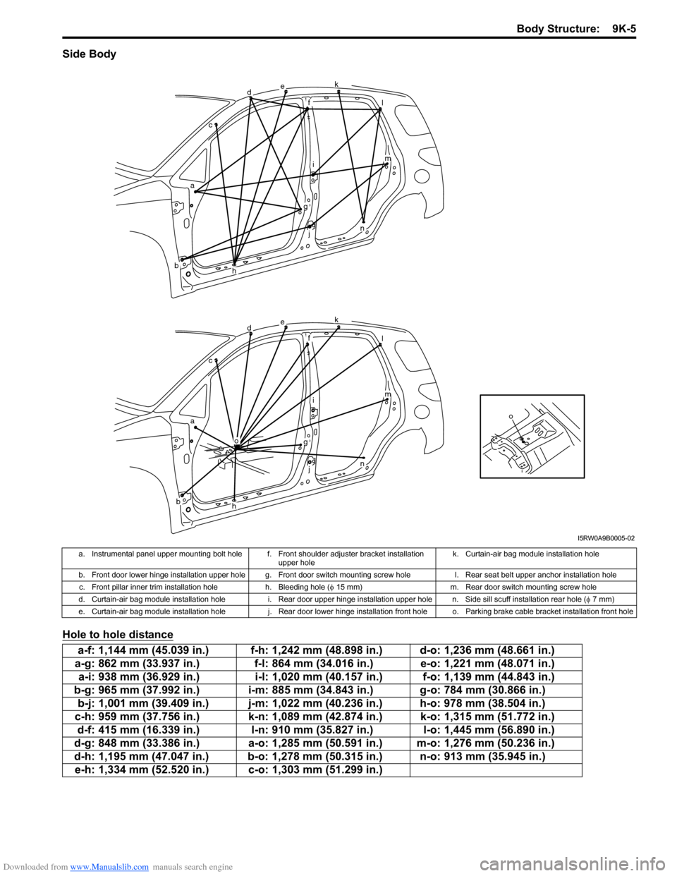
Side Body
Hole to hole distance
o
dek
fl
im
n
g
j
h
o
ac
b
dek
fl
im
n
g
j
h
ac
b
I5RW0A9B0005-02
a. Instrumental panel upper mounting bolt hole f. Front shoulder adjuster bracket installation
upper holek. Curtain-air bag module installation hole
b. Front door lower hinge installation upper hole g. Front door switch mounting screw hole l. Rear seat belt upper anchor installation hole
c. Front pillar inner trim installation hole h. Bleeding hole (φ 15 mm) m. Rear door switch mounting screw hole
d. Curtain-air bag module installation hole i. Rear door upper hinge installation upper hole n. Side sill scuff installation rear hole (φ 7 mm)
e. Curtain-air bag module installation hole j. Rear door lower hinge installation front hole o. Parking brake cable bracket installation front hole
a-f: 1,144 mm (45.039 in.) f-h: 1,242 mm (48.898 in.) d-o: 1,236 mm (48.661 in.)
a-g: 862 mm (33.937 in.) f-l: 864 mm (34.016 in.) e-o: 1,221 mm (48.071 in.)
a-i: 938 mm (36.929 in.) i-l: 1,020 mm (40.157 in.) f-o: 1,139 mm (44.843 in.)
b-g: 965 mm (37.992 in.) i-m: 885 mm (34.843 in.) g-o: 784 mm (30.866 in.)
b-j: 1,001 mm (39.409 in.) j-m: 1,022 mm (40.236 in.) h-o: 978 mm (38.504 in.)
c-h: 959 mm (37.756 in.) k-n: 1,089 mm (42.874 in.) k-o: 1,315 mm (51.772 in.)
d-f: 415 mm (16.339 in.) l-n: 910 mm (35.827 in.) l-o: 1,445 mm (56.890 in.)
d-g: 848 mm (33.386 in.) a-o: 1,285 mm (50.591 in.) m-o: 1,276 mm (50.236 in.)
d-h: 1,195 mm (47.047 in.) b-o: 1,278 mm (50.315 in.) n-o: 913 mm (35.945 in.)
e-h: 1,334 mm (52.520 in.) c-o: 1,303 mm (51.299 in.)
Page 1450 of 1556
Downloaded from www.Manualslib.com manuals search engine 9K-6 Body Structure:
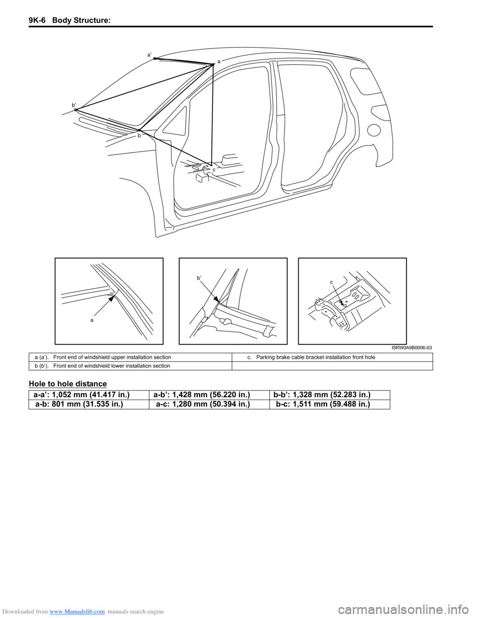
Hole to hole distance
c
a
a’a
b b’
c
b’
I5RW0A9B0006-03
a (a’). Front end of windshield upper installation section c. Parking brake cable bracket installation front hole
b (b’). Front end of windshield lower installation section
a-a’: 1,052 mm (41.417 in.) a-b’: 1,428 mm (56.220 in.) b-b’: 1,328 mm (52.283 in.)
a-b: 801 mm (31.535 in.) a-c: 1,280 mm (50.394 in.) b-c: 1,511 mm (59.488 in.)