section 9 SUZUKI SX4 2006 1.G Service Workshop Manual
[x] Cancel search | Manufacturer: SUZUKI, Model Year: 2006, Model line: SX4, Model: SUZUKI SX4 2006 1.GPages: 1556, PDF Size: 37.31 MB
Page 524 of 1556
Downloaded from www.Manualslib.com manuals search engine 3B-27 Differential:
DTC U0073: Control Module Communication Bus OffS6RW0D3204022
Refer to “Troubleshooting for CAN-DTC in Section 1A”.
DTC U0100: Lost Communication with ECMS6RW0D3204023
Refer to “Troubleshooting for CAN-DTC in Section 1A”.
DTC U0121: Lost Communication with ABS / ESP® Control ModuleS6RW0D3204024
Refer to “Troubleshooting for CAN-DTC in Section 1A”.
DTC U0155: Lost Communication with Instrument Panel Cluster (IPC) Control ModuleS6RW0D3204025
Refer to “Troubleshooting for CAN-DTC in Section 1A”.
Inspection of 4WD Control Module and Its CircuitsS6RW0D3204026
4WD control module and its circuits can be checked at coupler connected to 4WD control module by measuring
voltage, pulse signal.
CAUTION!
4WD control module cannot be checked by itself. It is strictly prohibited to connect voltmeter or
ohmmeter to 4WD control module with couplers disconnected from it.
Voltage and Signal Check
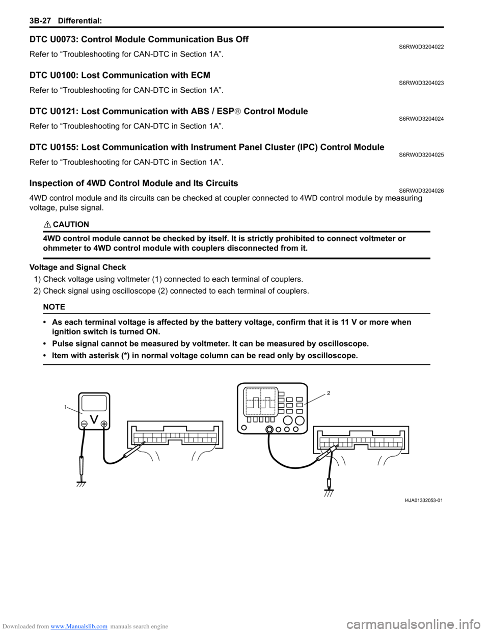
1) Check voltage using voltmeter (1) connected to each terminal of couplers.
2) Check signal using oscilloscope (2) connected to each terminal of couplers.
NOTE
• As each terminal voltage is affected by the battery voltage, confirm that it is 11 V or more when
ignition switch is turned ON.
• Pulse signal cannot be measured by voltmeter. It can be measured by oscilloscope.
• Item with asterisk (*) in normal voltage column can be read only by oscilloscope.
12
I4JA01332053-01
Page 528 of 1556
Downloaded from www.Manualslib.com manuals search engine 3B-31 Differential:
2WD/4WD Switch Removal and InstallationS6RW0D3206003
Removal
1) Disconnect negative cable at battery.
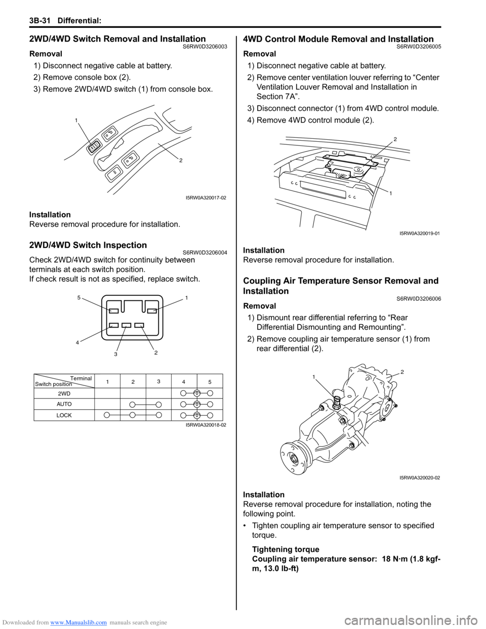
2) Remove console box (2).
3) Remove 2WD/4WD switch (1) from console box.
Installation
Reverse removal procedure for installation.
2WD/4WD Switch InspectionS6RW0D3206004
Check 2WD/4WD switch for continuity between
terminals at each switch position.
If check result is not as specified, replace switch.
4WD Control Module Removal and InstallationS6RW0D3206005
Removal
1) Disconnect negative cable at battery.
2) Remove center ventilation louver referring to “Center
Ventilation Louver Removal and Installation in
Section 7A”.
3) Disconnect connector (1) from 4WD control module.
4) Remove 4WD control module (2).
Installation
Reverse removal procedure for installation.
Coupling Air Temperature Sensor Removal and
Installation
S6RW0D3206006
Removal
1) Dismount rear differential referring to “Rear
Differential Dismounting and Remounting”.
2) Remove coupling air temperature sensor (1) from
rear differential (2).
Installation
Reverse removal procedure for installation, noting the
following point.
• Tighten coupling air temperature sensor to specified
torque.
Tightening torque
Coupling air temperature sensor: 18 N·m (1.8 kgf-
m, 13.0 lb-ft)
1
2
I5RW0A320017-02
Terminal
Switch position
2WD
AUTO
LOCK
11
22
3 3
4 4
5 5
I5RW0A320018-02
2
1
I5RW0A320019-01
12
I5RW0A320020-02
Page 531 of 1556
Downloaded from www.Manualslib.com manuals search engine Differential: 3B-34
Front Mounting Arm and/or Rear Mounting
Bracket Assembly Removal and Installation
S6RW0D3206010
Remove and install front mounting arm and/or rear
mounting bracket after rear differential removed.
For tightening torque of each bolt and nut, refer to “Rear
Differential Mountings Components”.
Rear Mounting Bracket Assembly Disassembly
and Reassembly
S6RW0D3206011
Disassembly
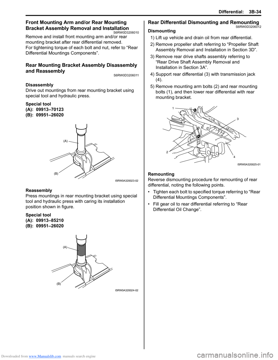
Drive out mountings from rear mounting bracket using
special tool and hydraulic press.
Special tool
(A): 09913–70123
(B): 09951–26020
Reassembly
Press mountings in rear mounting bracket using special
tool and hydraulic press with caring its installation
position shown in figure.
Special tool
(A): 09913–85210
(B): 09951–26020
Rear Differential Dismounting and RemountingS6RW0D3206012
Dismounting
1) Lift up vehicle and drain oil from rear differential.
2) Remove propeller shaft referring to “Propeller Shaft
Assembly Removal and Installation in Section 3D”.
3) Remove rear drive shafts assembly referring to
“Rear Drive Shaft Assembly Removal and
Installation in Section 3A”.
4) Support rear differential (3) with transmission jack
(4).
5) Remove mounting arm bolts (2) and rear mounting
bolts (1), and then lower rear differential with rear
mounting bracket.
Remounting
Reverse dismounting procedure for remounting of rear
differential, noting the following points.
• Tighten each bolt to specified torque referring to “Rear
Differential Mountings Components”.
• Fill gear oil to rear differential referring to “Rear
Differential Oil Change”.
(B)
(A)
I5RW0A320023-02
(A)
(B)
I5RW0A320024-02
3
4 21
I5RW0A320025-01
Page 543 of 1556
Downloaded from www.Manualslib.com manuals search engine Differential: 3B-46
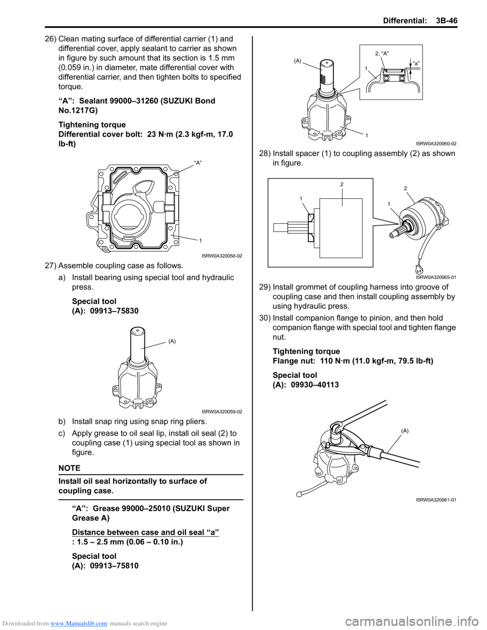
26) Clean mating surface of differential carrier (1) and
differential cover, apply sealant to carrier as shown
in figure by such amount that its section is 1.5 mm
(0.059 in.) in diameter, mate differential cover with
differential carrier, and then tighten bolts to specified
torque.
“A”: Sealant 99000–31260 (SUZUKI Bond
No.1217G)
Tightening torque
Differential cover bolt: 23 N·m (2.3 kgf-m, 17.0
lb-ft)
27) Assemble coupling case as follows.
a) Install bearing using special tool and hydraulic
press.
Special tool
(A): 09913–75830
b) Install snap ring using snap ring pliers.
c) Apply grease to oil seal lip, install oil seal (2) to
coupling case (1) using special tool as shown in
figure.
NOTE
Install oil seal horizontally to surface of
coupling case.
“A”: Grease 99000–25010 (SUZUKI Super
Grease A)
Distance between case and oil seal “a”
: 1.5 – 2.5 mm (0.06 – 0.10 in.)
Special tool
(A): 09913–7581028) Install spacer (1) to coupling assembly (2) as shown
in figure.
29) Install grommet of coupling harness into groove of
coupling case and then install coupling assembly by
using hydraulic press.
30) Install companion flange to pinion, and then hold
companion flange with special tool and tighten flange
nut.
Tightening torque
Flange nut: 110 N·m (11.0 kgf-m, 79.5 lb-ft)
Special tool
(A): 09930–40113
“A”
1
I5RW0A320058-02
(A)
I5RW0A320059-02
(A)
1 12, “A”“a”
I5RW0A320060-02
12
12
I5RW0A320065-01
(A)
I5RW0A320061-01
Page 544 of 1556

Downloaded from www.Manualslib.com manuals search engine 3B-47 Differential:
31) Clean mating surface of differential carrier (1) and
coupling case (2), apply sealant to carrier as shown
in figure by such amount that its section is 1.5 mm
(0.059 in.) in diameter, mate coupling case with
differential carrier as shown in figure, and then
tighten bolts to specified torque.
“A”: Sealant 99000–31260 (SUZUKI Bond
No.1217G)
Tightening torque
Coupling case bolt (a): 23 N·m (2.3 kgf-m, 17.0
lb-ft)
NOTE
Install coupling pin (3) by fitting it to groove
(4) of coupling case.
32) Apply grease to oil seal lip, and then install oil seals
(1) to rear differential (2) using special tool as shown
in figure.
NOTE
Install oil seal horizontally to surface of rear
differential case.
“A”: Grease 99000–25010 (SUZUKI Super
Grease A)
Distance between rear differential and oil seal
“a”
: 1.0 – 2.0 mm (0.04 – 0.08 in.)
Special tool
(A): 09913–75810
33) Install drive shaft flange.
34) Install rear mounting bracket to rear differential
referring to “Front Mounting Arm and/or Rear
Mounting Bracket Assembly Removal and
Installation”.
Rear Differential InspectionS6RW0D3206015
• Check companion flange for wear or damage.
• Check bearings for wear or discoloration.
• Check differential carrier for cracks.
• Check drive bevel pinion and bevel gear for wear or
cracks.
• Check side gears, pinion gears and pinion shaft for
wear or damage.
• Check side gear spline for wear or damage.
1 4
3 2“A”
(a)
I5RW0A320062-04
(A)
2 21, “A”
“a”
I5RW0A320063-02
Page 545 of 1556
Downloaded from www.Manualslib.com manuals search engine Differential: 3B-48
Specifications
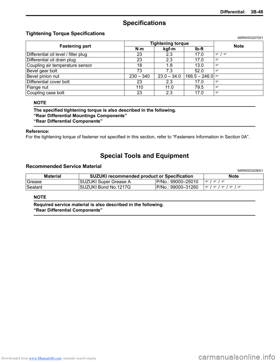
Tightening Torque SpecificationsS6RW0D3207001
NOTE
The specified tightening torque is also described in the following.
“Rear Differential Mountings Components”
“Rear Differential Components”
Reference:
For the tightening torque of fastener not specified in this section, refer to “Fasteners Information in Section 0A”.
Special Tools and Equipment
Recommended Service MaterialS6RW0D3208001
NOTE
Required service material is also described in the following.
“Rear Differential Components”
Fastening partTightening torque
Note
N⋅mkgf-mlb-ft
Differential oil level / filler plug 23 2.3 17.0�) / �)
Differential oil drain plug 23 2.3 17.0�)
Coupling air temperature sensor 18 1.8 13.0�)
Bevel gear bolt 73 7.3 52.0�)
Bevel pinion nut 230 – 340 23.0 – 34.0 166.5 – 246.0�)
Differential cover bolt 23 2.3 17.0�)
Flange nut 110 11.0 79.5�)
Coupling case bolt 23 2.3 17.0�)
Material SUZUKI recommended product or Specification Note
Grease SUZUKI Super Grease A P/No.: 99000–25010�) / �) / �)
Sealant SUZUKI Bond No.1217G P/No.: 99000–31260�) / �) / �) / �) / �)
Page 550 of 1556
Downloaded from www.Manualslib.com manuals search engine 3C-3 Transfer:
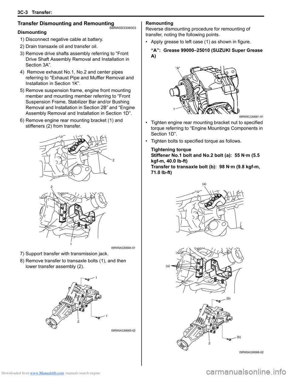
Transfer Dismounting and RemountingS6RW0D3306003
Dismounting
1) Disconnect negative cable at battery.
2) Drain transaxle oil and transfer oil.
3) Remove drive shafts assembly referring to “Front
Drive Shaft Assembly Removal and Installation in
Section 3A”.
4) Remove exhaust No.1, No.2 and center pipes
referring to “Exhaust Pipe and Muffler Removal and
Installation in Section 1K”.
5) Remove suspension frame, engine front mounting
member and mounting member referring to “Front
Suspension Frame, Stabilizer Bar and/or Bushing
Removal and Installation in Section 2B” and “Engine
Assembly Removal and Installation in Section 1D”.
6) Remove engine rear mounting bracket (1) and
stiffeners (2) from transfer.
7) Support transfer with transmission jack.
8) Remove transfer to transaxle bolts (1), and then
lower transfer assembly (2).Remounting
Reverse dismounting procedure for remounting of
transfer, noting the following points.
• Apply grease to left case (1) as shown in figure.
“A”: Grease 99000–25010 (SUZUKI Super Grease
A)
• Tighten engine rear mounting bracket nut to specified
torque referring to “Engine Mountings Components in
Section 1D”.
• Tighten bolts to specified torque as follows.
Tightening torque
Stiffener No.1 bolt and No.2 bolt (a): 55 N·m (5.5
kgf-m, 40.0 lb-ft)
Transfer to transaxle bolt (b): 98 N·m (9.8 kgf-m,
71.0 lb-ft)
2
2
1I5RW0A330004-01
1
1
2
I5RW0A330005-02
I5RW0C330001-01
(a)
(a)
(b)
(b)
2
I5RW0A330006-02
Page 551 of 1556
Downloaded from www.Manualslib.com manuals search engine Transfer: 3C-4
• Pour transaxle oil and transfer oil referring to “Manual
Transaxle Oil Change in Section 5B” and “Transfer Oil
Change”.
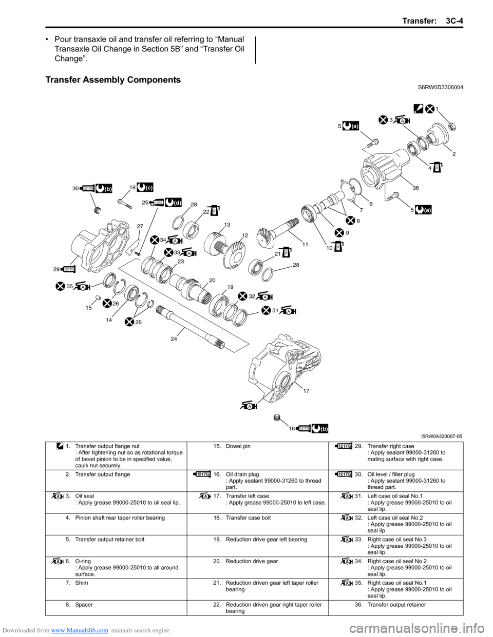
Transfer Assembly ComponentsS6RW0D3306004
1
2
6
9
1110
8
7
3A
4
5
36
OIL
(a) 5
(a)
OIL
28
18
30
27
25
21
28
13
12
22OIL
OIL
32A
31A
1322(d)
34A
33
23A
2019
(c)1217G
291217G
(b)
35
15A
26
26 14
24
17
161217G(b)
A
I5RW0A330007-05
1. Transfer output flange nut
: After tightening nut so as rotational torque
of bevel pinion to be in specified value,
caulk nut securely.15. Dowel pin 29. Transfer right case
: Apply sealant 99000-31260 to
mating surface with right case.
2. Transfer output flange 16. Oil drain plug
: Apply sealant 99000-31260 to thread
part.30. Oil level / filler plug
: Apply sealant 99000-31260 to
thread part.
3. Oil seal
: Apply grease 99000-25010 to oil seal lip.17. Transfer left case
: Apply grease 99000-25010 to left case.31. Left case oil seal No.1
: Apply grease 99000-25010 to oil
seal lip.
4. Pinion shaft rear taper roller bearing 18. Transfer case bolt 32. Left case oil seal No.2
: Apply grease 99000-25010 to oil
seal lip.
5. Transfer output retainer bolt 19. Reduction drive gear left bearing 33. Right case oil seal No.3
: Apply grease 99000-25010 to oil
seal lip.
6. O-ring
: Apply grease 99000-25010 to all around
surface.20. Reduction drive gear 34. Right case oil seal No.2
: Apply grease 99000-25010 to oil
seal lip.
7. Shim 21. Reduction driven gear left taper roller
bearing35. Right case oil seal No.1
: Apply grease 99000-25010 to oil
seal lip.
8. Spacer 22. Reduction driven gear right taper roller
bearing36. Transfer output retainer
Page 553 of 1556
Downloaded from www.Manualslib.com manuals search engine Transfer: 3C-6
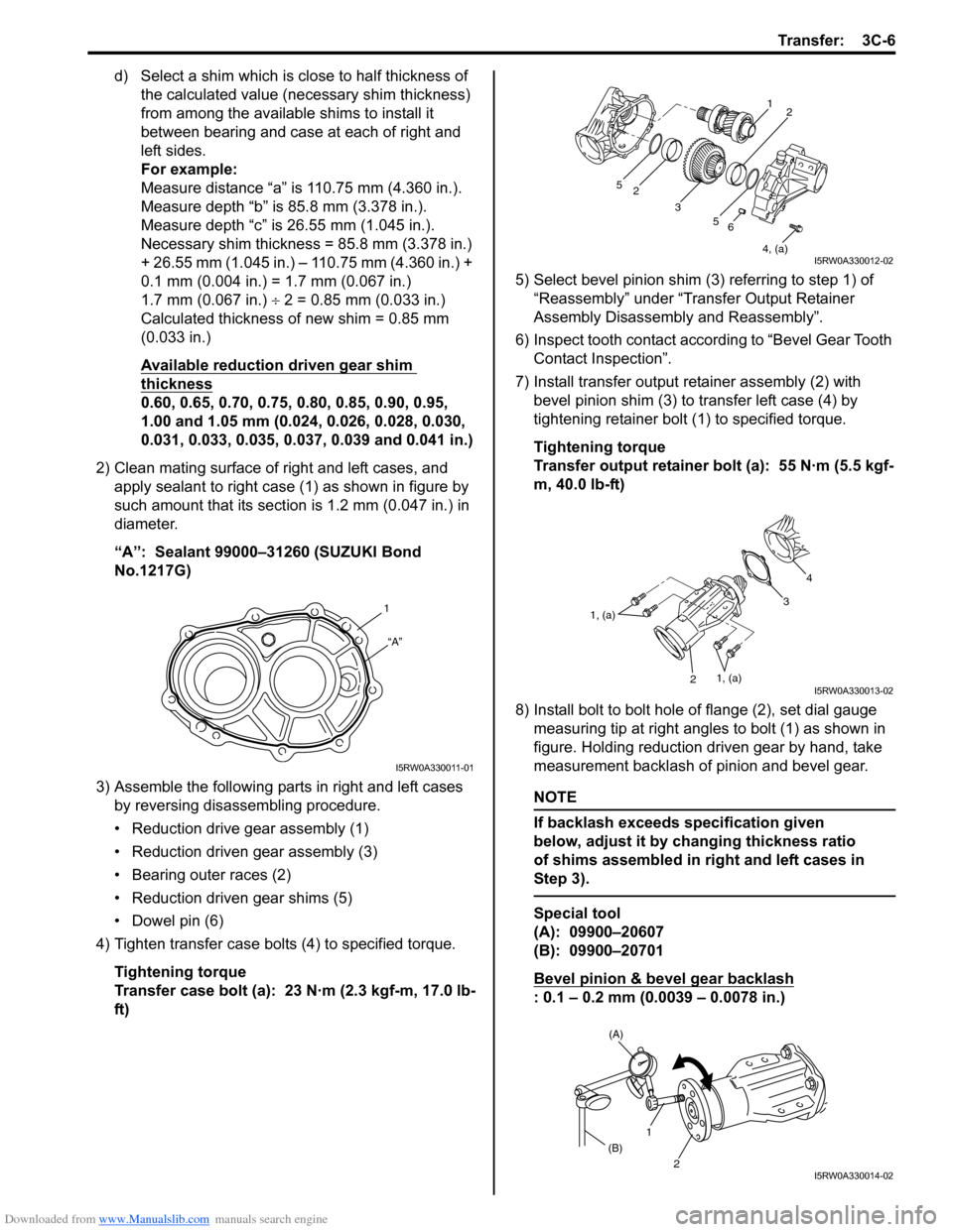
d) Select a shim which is close to half thickness of
the calculated value (necessary shim thickness)
from among the available shims to install it
between bearing and case at each of right and
left sides.
For example:
Measure distance “a” is 110.75 mm (4.360 in.).
Measure depth “b” is 85.8 mm (3.378 in.).
Measure depth “c” is 26.55 mm (1.045 in.).
Necessary shim thickness = 85.8 mm (3.378 in.)
+ 26.55 mm (1.045 in.) – 110.75 mm (4.360 in.) +
0.1 mm (0.004 in.) = 1.7 mm (0.067 in.)
1.7 mm (0.067 in.) ÷ 2 = 0.85 mm (0.033 in.)
Calculated thickness of new shim = 0.85 mm
(0.033 in.)
Available reduction driven gear shim
thickness
0.60, 0.65, 0.70, 0.75, 0.80, 0.85, 0.90, 0.95,
1.00 and 1.05 mm (0.024, 0.026, 0.028, 0.030,
0.031, 0.033, 0.035, 0.037, 0.039 and 0.041 in.)
2) Clean mating surface of right and left cases, and
apply sealant to right case (1) as shown in figure by
such amount that its section is 1.2 mm (0.047 in.) in
diameter.
“A”: Sealant 99000–31260 (SUZUKI Bond
No.1217G)
3) Assemble the following parts in right and left cases
by reversing disassembling procedure.
• Reduction drive gear assembly (1)
• Reduction driven gear assembly (3)
• Bearing outer races (2)
• Reduction driven gear shims (5)
• Dowel pin (6)
4) Tighten transfer case bolts (4) to specified torque.
Tightening torque
Transfer case bolt (a): 23 N·m (2.3 kgf-m, 17.0 lb-
ft)5) Select bevel pinion shim (3) referring to step 1) of
“Reassembly” under “Transfer Output Retainer
Assembly Disassembly and Reassembly”.
6) Inspect tooth contact according to “Bevel Gear Tooth
Contact Inspection”.
7) Install transfer output retainer assembly (2) with
bevel pinion shim (3) to transfer left case (4) by
tightening retainer bolt (1) to specified torque.
Tightening torque
Transfer output retainer bolt (a): 55 N·m (5.5 kgf-
m, 40.0 lb-ft)
8) Install bolt to bolt hole of flange (2), set dial gauge
measuring tip at right angles to bolt (1) as shown in
figure. Holding reduction driven gear by hand, take
measurement backlash of pinion and bevel gear.
NOTE
If backlash exceeds specification given
below, adjust it by changing thickness ratio
of shims assembled in right and left cases in
Step 3).
Special tool
(A): 09900–20607
(B): 09900–20701
Bevel pinion & bevel gear backlash
: 0.1 – 0.2 mm (0.0039 – 0.0078 in.)
1
“A”
I5RW0A330011-01
6
4, (a) 5 2
31
2
5
I5RW0A330012-02
4
3
21, (a)
1, (a)
I5RW0A330013-02
(A)
1
(B)
2
I5RW0A330014-02
Page 563 of 1556
Downloaded from www.Manualslib.com manuals search engine Transfer: 3C-16
Specifications
Tightening Torque SpecificationsS6RW0D3307001
NOTE
The specified tightening torque is also described in the following.
“Transfer Assembly Components”
Reference:
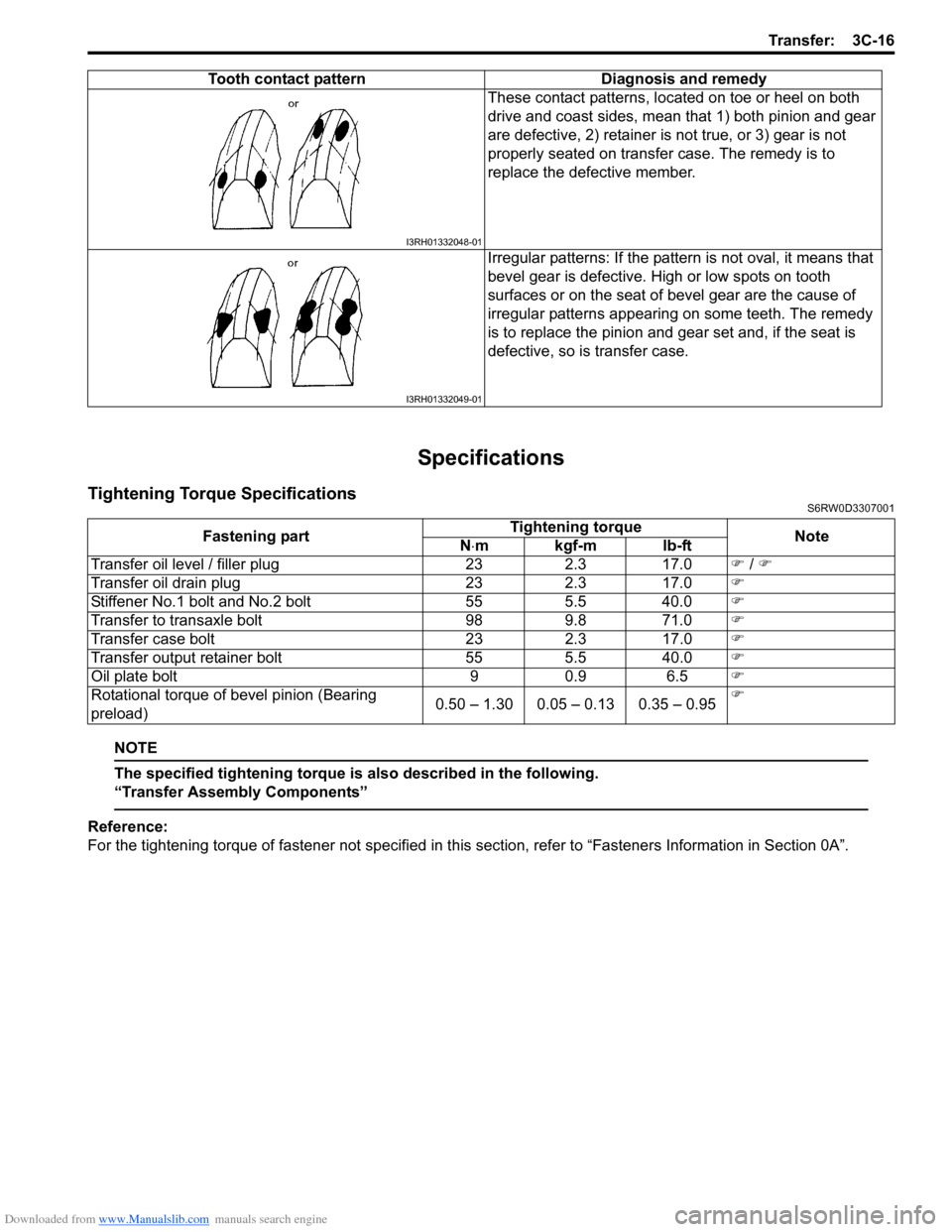
For the tightening torque of fastener not specified in this section, refer to “Fasteners Information in Section 0A”. These contact patterns, located on toe or heel on both
drive and coast sides, mean that 1) both pinion and gear
are defective, 2) retainer is not true, or 3) gear is not
properly seated on transfer case. The remedy is to
replace the defective member.
Irregular patterns: If the pattern is not oval, it means that
bevel gear is defective. High or low spots on tooth
surfaces or on the seat of bevel gear are the cause of
irregular patterns appearing on some teeth. The remedy
is to replace the pinion and gear set and, if the seat is
defective, so is transfer case. Tooth contact pattern Diagnosis and remedy
I3RH01332048-01
I3RH01332049-01
Fastening partTightening torque
Note
N⋅mkgf-mlb-ft
Transfer oil level / filler plug 23 2.3 17.0�) / �)
Transfer oil drain plug 23 2.3 17.0�)
Stiffener No.1 bolt and No.2 bolt 55 5.5 40.0�)
Transfer to transaxle bolt 98 9.8 71.0�)
Transfer case bolt 23 2.3 17.0�)
Transfer output retainer bolt 55 5.5 40.0�)
Oil plate bolt 9 0.9 6.5�)
Rotational torque of bevel pinion (Bearing
preload)0.50 – 1.30 0.05 – 0.13 0.35 – 0.95�)