engine mount SUZUKI SX4 2006 1.G Service Owner's Manual
[x] Cancel search | Manufacturer: SUZUKI, Model Year: 2006, Model line: SX4, Model: SUZUKI SX4 2006 1.GPages: 1556, PDF Size: 37.31 MB
Page 253 of 1556
Downloaded from www.Manualslib.com manuals search engine Engine General Information and Diagnosis: 1A-203
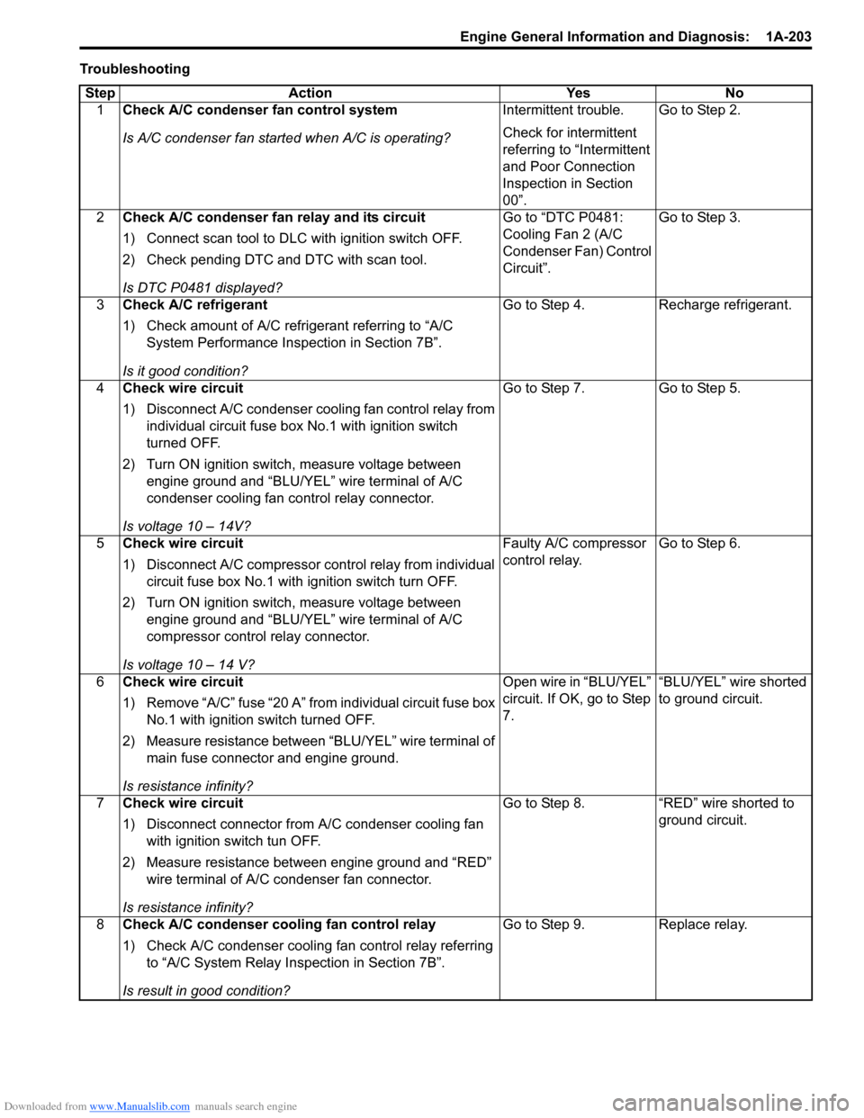
Troubleshooting
Step Action Yes No
1Check A/C condenser fan control system
Is A/C condenser fan started when A/C is operating?Intermittent trouble.
Check for intermittent
referring to “Intermittent
and Poor Connection
Inspection in Section
00”.Go to Step 2.
2Check A/C condenser fan relay and its circuit
1) Connect scan tool to DLC with ignition switch OFF.
2) Check pending DTC and DTC with scan tool.
Is DTC P0481 displayed?Go to “DTC P0481:
Cooling Fan 2 (A/C
Condenser Fan) Control
Circuit”.Go to Step 3.
3Check A/C refrigerant
1) Check amount of A/C refrigerant referring to “A/C
System Performance Inspection in Section 7B”.
Is it good condition?Go to Step 4. Recharge refrigerant.
4Check wire circuit
1) Disconnect A/C condenser cooling fan control relay from
individual circuit fuse box No.1 with ignition switch
turned OFF.
2) Turn ON ignition switch, measure voltage between
engine ground and “BLU/YEL” wire terminal of A/C
condenser cooling fan control relay connector.
Is voltage 10 – 14V?Go to Step 7. Go to Step 5.
5Check wire circuit
1) Disconnect A/C compressor control relay from individual
circuit fuse box No.1 with ignition switch turn OFF.
2) Turn ON ignition switch, measure voltage between
engine ground and “BLU/YEL” wire terminal of A/C
compressor control relay connector.
Is voltage 10 – 14 V?Faulty A/C compressor
control relay.Go to Step 6.
6Check wire circuit
1) Remove “A/C” fuse “20 A” from individual circuit fuse box
No.1 with ignition switch turned OFF.
2) Measure resistance between “BLU/YEL” wire terminal of
main fuse connector and engine ground.
Is resistance infinity?Open wire in “BLU/YEL”
circuit. If OK, go to Step
7.“BLU/YEL” wire shorted
to ground circuit.
7Check wire circuit
1) Disconnect connector from A/C condenser cooling fan
with ignition switch tun OFF.
2) Measure resistance between engine ground and “RED”
wire terminal of A/C condenser fan connector.
Is resistance infinity?Go to Step 8. “RED” wire shorted to
ground circuit.
8Check A/C condenser cooling fan control relay
1) Check A/C condenser cooling fan control relay referring
to “A/C System Relay Inspection in Section 7B”.
Is result in good condition?Go to Step 9. Replace relay.
Page 257 of 1556

Downloaded from www.Manualslib.com manuals search engine Engine General Information and Diagnosis: 1A-207
6A/C evaporator outlet air temp. sensor check
1) Disconnect connectors from ECM with ignition switch
turned OFF.
2) Check for proper connection to “E01-57” and “E01-54”
wire terminals of ECM connector.
3) If OK, measure resistance between “E01-57” and “E01-
54” wire terminals of ECM connector.
Evaporator temp. sensor resistance
At 0 °C: 6.3 – 6.9 kΩ
At 25 °C: 1.8 – 2.2 kΩ
Is resistance within specification?Go to Step 7. Faulty A/C evaporator
outlet air temp. sensor
or its circuit.
7DTC check of A/C refrigerant pressure sensor circuit
1) Connect scan tool to DLC with ignition switch turned
OFF.
2) Turn ON ignition switch.
3) Check ECM for DTC of A/C refrigerant pressure sensor
circuit.
Is there DTC P0532 or DTC P0533?Go to applicable DTC
diag. flow.Go to Step 8.
8A/C refrigerant pressure sensor voltage check
1) Check A/C refrigerant pressure sensor voltage referring
to “Inspection of ECM and Its Circuits”.
Is voltage within specified value?Go to Step 9. Check amount of
refrigerant. If OK,
replace A/C refrigerant
pressure sensor.
9A/C condenser cooling fan check
1) Check A/C condenser cooling fan referring to
“Condenser Cooling Fan Inspection in Section 7B”.
Is check result satisfactory?A/C condenser cooling
fan drive circuit
malfunction. If circuit is
OK, go to Step 6.Replace A/C condenser
cooling fan motor.
10A/C compressor control system check
Is A/C compressor started when A/C and blower speed
selector switch are turned ON with engine running?A/C system is in good
condition.Go to Step 11. Step Action Yes No
7
6
5
4
3
2
1
10
20
30
4050 010
2030
60 70
80 ResistanceTemperatureI3RB0A110053-01
Page 269 of 1556
Downloaded from www.Manualslib.com manuals search engine Engine Electrical Devices: 1C-1
Engine
Engine Electrical Devices
Repair Instructions
Engine Control Module (ECM) Removal and
Installation
S6RW0D1306001
CAUTION!
As ECM consists of precision parts, be
careful not to expose it to excessive shock.
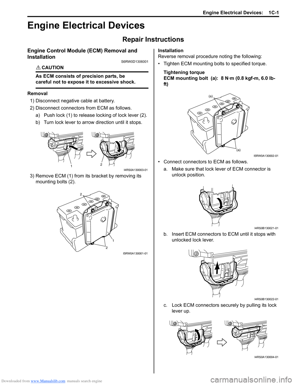
Removal
1) Disconnect negative cable at battery.
2) Disconnect connectors from ECM as follows.
a) Push lock (1) to release locking of lock lever (2).
b) Turn lock lever to arrow direction until it stops.
3) Remove ECM (1) from its bracket by removing its
mounting bolts (2).Installation
Reverse removal procedure noting the following:
• Tighten ECM mounting bolts to specified torque.
Tightening torque
ECM mounting bolt (a): 8 N·m (0.8 kgf-m, 6.0 lb-
ft)
• Connect connectors to ECM as follows.
a. Make sure that lock lever of ECM connector is
unlock position.
b. Insert ECM connectors to ECM until it stops with
unlocked lock lever.
c. Lock ECM connectors securely by pulling its lock
lever up.
12I4RS0A130003-01
1
2 2
I5RW0A130001-01
(a) (a)
I5RW0A130002-01
I4RS0B130021-01
I4RS0B130022-01
I4RS0A130004-01
Page 273 of 1556
Downloaded from www.Manualslib.com manuals search engine Engine Electrical Devices: 1C-5
Electric Throttle Body System CalibrationS6RW0D1306004
NOTE
If the service described under the
“Precautions of Electric Throttle Body
System Calibration in Section 1A” is
performed, calibrate electric throttle body
system as follows.
1) If electric throttle body assembly and/or accelerator
pedal position (APP) sensor assembly are replaced,
perform following steps.
a) Disconnect negative cable at battery for 20
seconds or more for the purpose of clearing
calibration data of closed throttle position from
memory in ECM.
b) Connect negative cable to battery.
2) Keep ignition switch at ON position for 5 seconds or
more without running engine.
Accelerator Pedal Position (APP) Sensor
Assembly On-Vehicle Inspection
S6RW0D1306005
1) Check that APP sensor assembly has been mounted
to vehicle body properly (no pinched floor carpet,
etc.).
If mounting is not properly, reinstall APP sensor
assembly properly referring to “Accelerator Pedal
Position (APP) Sensor Assembly Removal and
Installation”.
2) Connect scan tool to DLC with ignition switch turned
OFF.
3) Turn ON ignition switch and select “Data List” mode
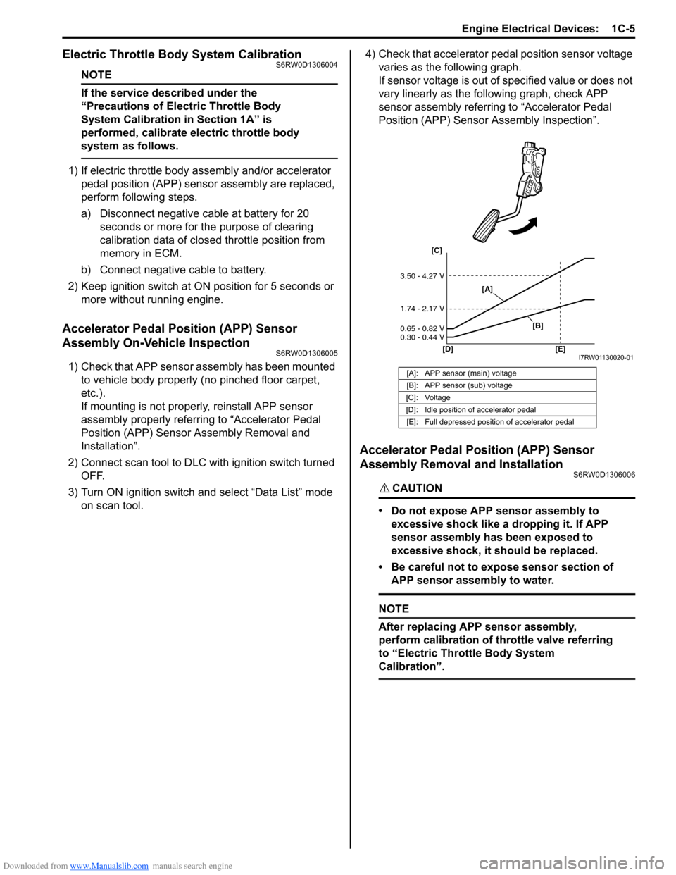
on scan tool.4) Check that accelerator pedal position sensor voltage
varies as the following graph.
If sensor voltage is out of specified value or does not
vary linearly as the following graph, check APP
sensor assembly referring to “Accelerator Pedal
Position (APP) Sensor Assembly Inspection”.
Accelerator Pedal Position (APP) Sensor
Assembly Removal and Installation
S6RW0D1306006
CAUTION!
• Do not expose APP sensor assembly to
excessive shock like a dropping it. If APP
sensor assembly has been exposed to
excessive shock, it should be replaced.
• Be careful not to expose sensor section of
APP sensor assembly to water.
NOTE
After replacing APP sensor assembly,
perform calibration of throttle valve referring
to “Electric Throttle Body System
Calibration”.
[A]: APP sensor (main) voltage
[B]: APP sensor (sub) voltage
[C]: Voltage
[D]: Idle position of accelerator pedal
[E]: Full depressed position of accelerator pedal
[C]
[D] [E]
3.50 - 4.27 V
1.74 - 2.17 V
0.65 - 0.82 V
0.30 - 0.44 V
[A]
[B]
I7RW01130020-01
Page 282 of 1556
Downloaded from www.Manualslib.com manuals search engine 1C-14 Engine Electrical Devices:
Specifications
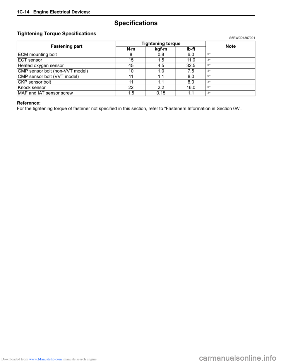
Tightening Torque SpecificationsS6RW0D1307001
Reference:
For the tightening torque of fastener not specified in this section, refer to “Fasteners Information in Section 0A”. Fastening partTightening torque
Note
N⋅mkgf-mlb-ft
ECM mounting bolt 8 0.8 6.0�)
ECT sensor 15 1.5 11.0�)
Heated oxygen sensor 45 4.5 32.5�)
CMP sensor bolt (non-VVT model) 10 1.0 7.5�)
CMP sensor bolt (VVT model) 11 1.1 8.0�)
CKP sensor bolt 11 1.1 8.0�)
Knock sensor 22 2.2 16.0�)
MAF and IAT sensor screw 1.5 0.15 1.1�)
Page 283 of 1556
Downloaded from www.Manualslib.com manuals search engine Engine Mechanical: 1D-1
Engine
Engine Mechanical
General Description
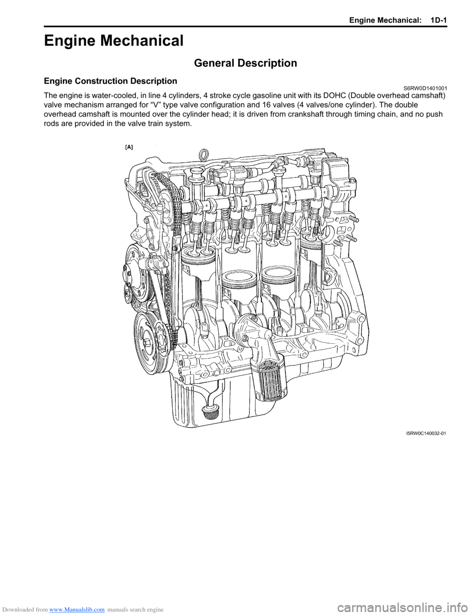
Engine Construction DescriptionS6RW0D1401001
The engine is water-cooled, in line 4 cylinders, 4 stroke cycle gasoline unit with its DOHC (Double overhead camshaft)
valve mechanism arranged for “V” type valve configuration and 16 valves (4 valves/one cylinder). The double
overhead camshaft is mounted over the cylinder head; it is driven from crankshaft through timing chain, and no push
rods are provided in the valve train system.
I5RW0C140032-01
Page 293 of 1556
Downloaded from www.Manualslib.com manuals search engine Engine Mechanical: 1D-11
Air Cleaner Assembly Removal and InstallationS6RW0D1406046
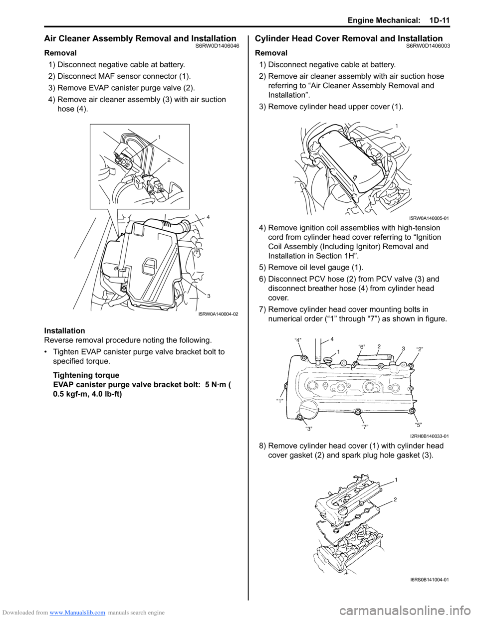
Removal
1) Disconnect negative cable at battery.
2) Disconnect MAF sensor connector (1).
3) Remove EVAP canister purge valve (2).
4) Remove air cleaner assembly (3) with air suction
hose (4).
Installation
Reverse removal procedure noting the following.
• Tighten EVAP canister purge valve bracket bolt to
specified torque.
Tightening torque
EVAP canister purge valve bracket bolt: 5 N·m (
0.5 kgf-m, 4.0 lb-ft)
Cylinder Head Cover Removal and InstallationS6RW0D1406003
Removal
1) Disconnect negative cable at battery.
2) Remove air cleaner assembly with air suction hose
referring to “Air Cleaner Assembly Removal and
Installation”.
3) Remove cylinder head upper cover (1).
4) Remove ignition coil assemblies with high-tension
cord from cylinder head cover referring to “Ignition
Coil Assembly (Including Ignitor) Removal and
Installation in Section 1H”.
5) Remove oil level gauge (1).
6) Disconnect PCV hose (2) from PCV valve (3) and
disconnect breather hose (4) from cylinder head
cover.
7) Remove cylinder head cover mounting bolts in
numerical order (“1” through “7”) as shown in figure.
8) Remove cylinder head cover (1) with cylinder head
cover gasket (2) and spark plug hole gasket (3).
1
2
3
4
I5RW0A140004-02
1
I5RW0A140005-01
I2RH0B140033-01
I6RS0B141004-01
Page 295 of 1556
Downloaded from www.Manualslib.com manuals search engine Engine Mechanical: 1D-13
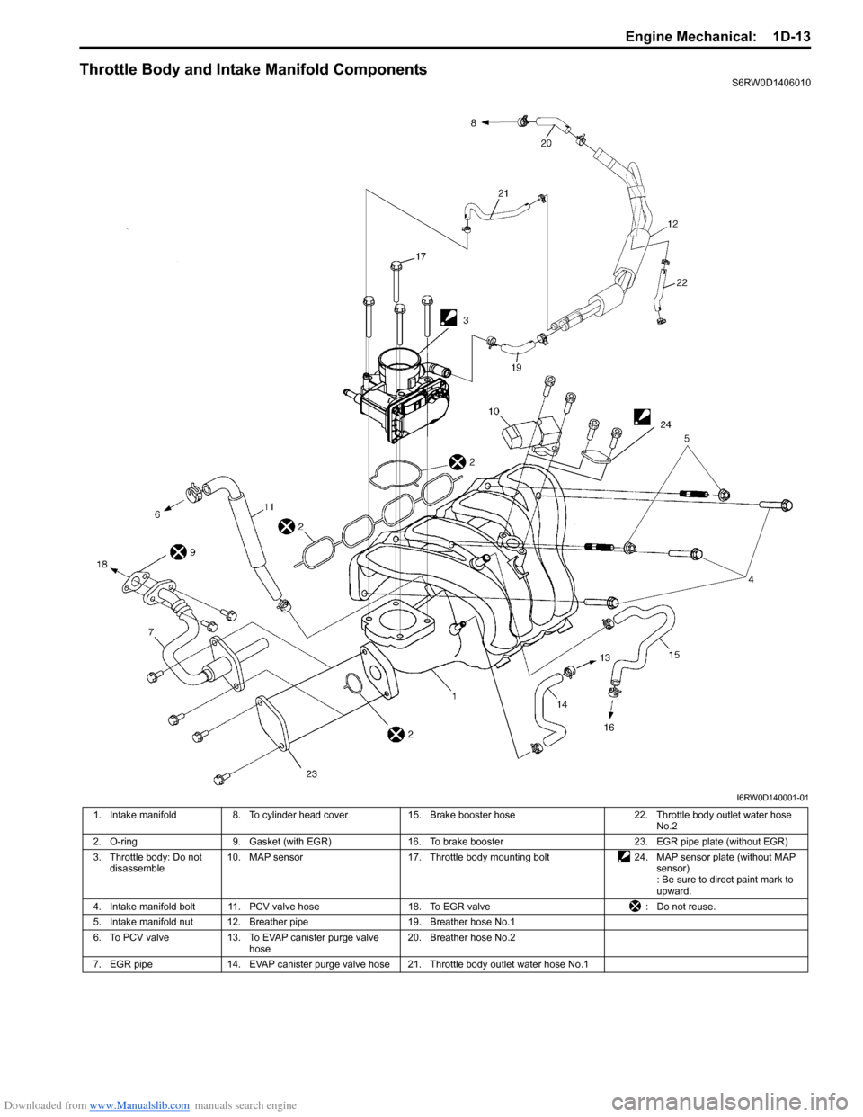
Throttle Body and Intake Manifold ComponentsS6RW0D1406010
I6RW0D140001-01
1. Intake manifold 8. To cylinder head cover 15. Brake booster hose 22. Throttle body outlet water hose
No.2
2. O-ring 9. Gasket (with EGR) 16. To brake booster 23. EGR pipe plate (without EGR)
3. Throttle body: Do not
disassemble10. MAP sensor 17. Throttle body mounting bolt 24. MAP sensor plate (without MAP
sensor)
: Be sure to direct paint mark to
upward.
4. Intake manifold bolt 11. PCV valve hose 18. To EGR valve : Do not reuse.
5. Intake manifold nut 12. Breather pipe 19. Breather hose No.1
6. To PCV valve 13. To EVAP canister purge valve
hose20. Breather hose No.2
7. EGR pipe 14. EVAP canister purge valve hose 21. Throttle body outlet water hose No.1
Page 298 of 1556
![SUZUKI SX4 2006 1.G Service Owners Manual Downloaded from www.Manualslib.com manuals search engine 1D-16 Engine Mechanical:
Engine Mountings ComponentsS6RW0D1406012
I6RW0D140002-01
[A]: For 4WD model 4. Engine left mounting
: Be sure to dire SUZUKI SX4 2006 1.G Service Owners Manual Downloaded from www.Manualslib.com manuals search engine 1D-16 Engine Mechanical:
Engine Mountings ComponentsS6RW0D1406012
I6RW0D140002-01
[A]: For 4WD model 4. Engine left mounting
: Be sure to dire](/img/20/7612/w960_7612-297.png)
Downloaded from www.Manualslib.com manuals search engine 1D-16 Engine Mechanical:
Engine Mountings ComponentsS6RW0D1406012
I6RW0D140002-01
[A]: For 4WD model 4. Engine left mounting
: Be sure to direct paint mark to forward.12. Dynamic damper
[B]: For 2WD model 5. Engine rear mounting
: Be sure to direct paint mark to forward.13. Mounting member cushion
[C]: For M/T model 6. Engine rear mounting No.1 bracket 14. Yellow mark
[D]: For A/T model 7. Engine rear mounting No.2 bracket 15. Mounting member
Page 299 of 1556
Downloaded from www.Manualslib.com manuals search engine Engine Mechanical: 1D-17
Engine Assembly Removal and InstallationS6RW0D1406013
Removal
1) Relieve fuel pressure according to “Fuel Pressure
Relief Procedure in Section 1G”.
2) Disconnect negative and positive cable at battery.
3) Disconnect ECM connectors.
4) Remove battery and battery tray with ECM.
5) Remove right and left side engine under covers.
6) Remove A/C compressor belt by referring to
“Compressor Drive Belt Removal and Installation in
Section 7B” or “Compressor Drive Belt Removal and
Installation in Section 7B”.
7) Drain engine oil referring to “Engine Oil and Filter
Change in Section 0B”.
8) Drain transaxle oil referring to “Manual Transaxle Oil
Change in Section 5B” or “A/T Fluid Change in
Section 5A”.
9) Drain transfer oil referring to “Transfer Oil Change in
Section 3C”.
10) Drain coolant referring to “Cooling System Draining
in Section 1F”
11) Remove air cleaner assembly referring to “Air
Cleaner Assembly Removal and Installation”.
12) With hose connected, detach A/C compressor from
its bracket referring to “Compressor Assembly
Removal and Installation in Section 7B” or
“Compressor Assembly Removal and Installation in
Section 7B”.
CAUTION!
Suspend removed A/C compressor at a place
where no damage will be caused during
removal and installation of engine assembly.
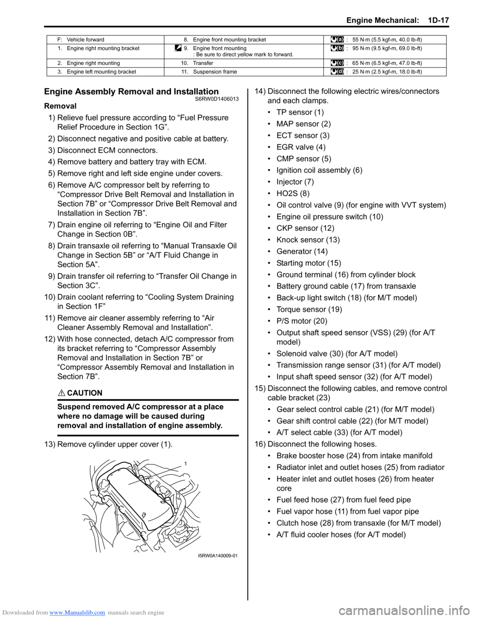
13) Remove cylinder upper cover (1).14) Disconnect the following electric wires/connectors
and each clamps.
• TP sensor (1)
• MAP sensor (2)
• ECT sensor (3)
•EGR valve (4)
• CMP sensor (5)
• Ignition coil assembly (6)
• Injector (7)
•HO2S (8)
• Oil control valve (9) (for engine with VVT system)
• Engine oil pressure switch (10)
• CKP sensor (12)
• Knock sensor (13)
• Generator (14)
• Starting motor (15)
• Ground terminal (16) from cylinder block
• Battery ground cable (17) from transaxle
• Back-up light switch (18) (for M/T model)
• Torque sensor (19)
• P/S motor (20)
• Output shaft speed sensor (VSS) (29) (for A/T
model)
• Solenoid valve (30) (for A/T model)
• Transmission range sensor (31) (for A/T model)
• Input shaft speed sensor (32) (for A/T model)
15) Disconnect the following cables, and remove control
cable bracket (23)
• Gear select control cable (21) (for M/T model)
• Gear shift control cable (22) (for M/T model)
• A/T select cable (33) (for A/T model)
16) Disconnect the following hoses.
• Brake booster hose (24) from intake manifold
• Radiator inlet and outlet hoses (25) from radiator
• Heater inlet and outlet hoses (26) from heater
core
• Fuel feed hose (27) from fuel feed pipe
• Fuel vapor hose (11) from fuel vapor pipe
• Clutch hose (28) from transaxle (for M/T model)
• A/T fluid cooler hoses (for A/T model)
F: Vehicle forward 8. Engine front mounting bracket : 55 N⋅m (5.5 kgf-m, 40.0 lb-ft)
1. Engine right mounting bracket 9. Engine front mounting
: Be sure to direct yellow mark to forward.: 95 N⋅m (9.5 kgf-m, 69.0 lb-ft)
2. Engine right mounting 10. Transfer : 65 N⋅m (6.5 kgf-m, 47.0 lb-ft)
3. Engine left mounting bracket 11. Suspension frame : 25 N⋅m (2.5 kgf-m, 18.0 lb-ft)
1
I5RW0A140009-01