fuel injector SUZUKI SX4 2006 1.G Service Owner's Manual
[x] Cancel search | Manufacturer: SUZUKI, Model Year: 2006, Model line: SX4, Model: SUZUKI SX4 2006 1.GPages: 1556, PDF Size: 37.31 MB
Page 161 of 1556
Downloaded from www.Manualslib.com manuals search engine Engine General Information and Diagnosis: 1A-111
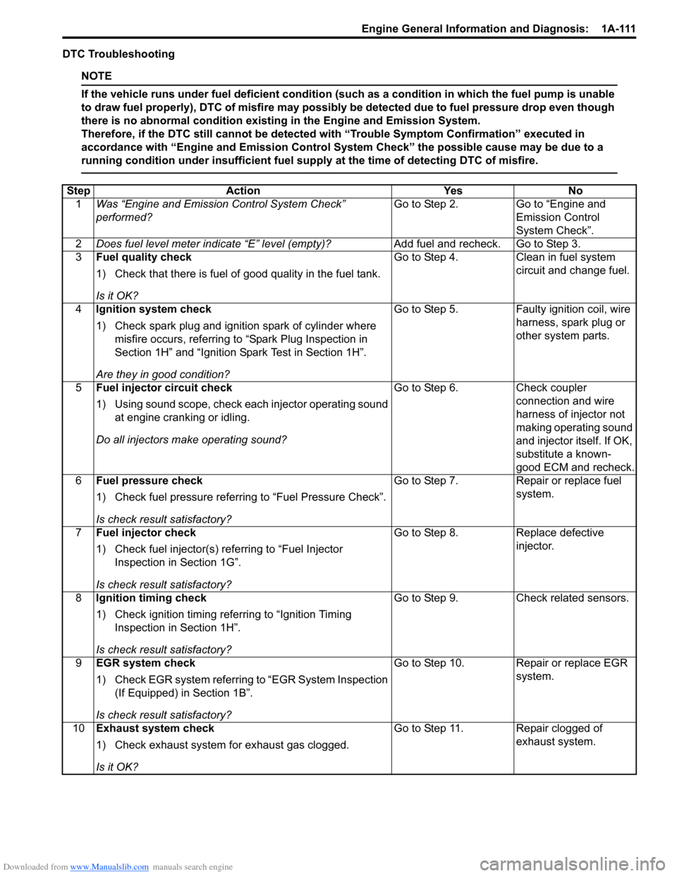
DTC Troubleshooting
NOTE
If the vehicle runs under fuel deficient condition (such as a condition in which the fuel pump is unable
to draw fuel properly), DTC of misfire may possibly be detected due to fuel pressure drop even though
there is no abnormal condition existing in the Engine and Emission System.
Therefore, if the DTC still cannot be detected with “Trouble Symptom Confirmation” executed in
accordance with “Engine and Emission Control System Check” the possible cause may be due to a
running condition under insufficient fuel supply at the time of detecting DTC of misfire.
Step Action Yes No
1Was “Engine and Emission Control System Check”
performed?Go to Step 2. Go to “Engine and
Emission Control
System Check”.
2Does fuel level meter indicate “E” level (empty)?Add fuel and recheck. Go to Step 3.
3Fuel quality check
1) Check that there is fuel of good quality in the fuel tank.
Is it OK?Go to Step 4. Clean in fuel system
circuit and change fuel.
4Ignition system check
1) Check spark plug and ignition spark of cylinder where
misfire occurs, referring to “Spark Plug Inspection in
Section 1H” and “Ignition Spark Test in Section 1H”.
Are they in good condition?Go to Step 5. Faulty ignition coil, wire
harness, spark plug or
other system parts.
5Fuel injector circuit check
1) Using sound scope, check each injector operating sound
at engine cranking or idling.
Do all injectors make operating sound?Go to Step 6. Check coupler
connection and wire
harness of injector not
making operating sound
and injector itself. If OK,
substitute a known-
good ECM and recheck.
6Fuel pressure check
1) Check fuel pressure referring to “Fuel Pressure Check”.
Is check result satisfactory?Go to Step 7. Repair or replace fuel
system.
7Fuel injector check
1) Check fuel injector(s) referring to “Fuel Injector
Inspection in Section 1G”.
Is check result satisfactory?Go to Step 8. Replace defective
injector.
8Ignition timing check
1) Check ignition timing referring to “Ignition Timing
Inspection in Section 1H”.
Is check result satisfactory?Go to Step 9. Check related sensors.
9EGR system check
1) Check EGR system referring to “EGR System Inspection
(If Equipped) in Section 1B”.
Is check result satisfactory?Go to Step 10. Repair or replace EGR
system.
10Exhaust system check
1) Check exhaust system for exhaust gas clogged.
Is it OK?Go to Step 11. Repair clogged of
exhaust system.
Page 162 of 1556
Downloaded from www.Manualslib.com manuals search engine 1A-112 Engine General Information and Diagnosis:
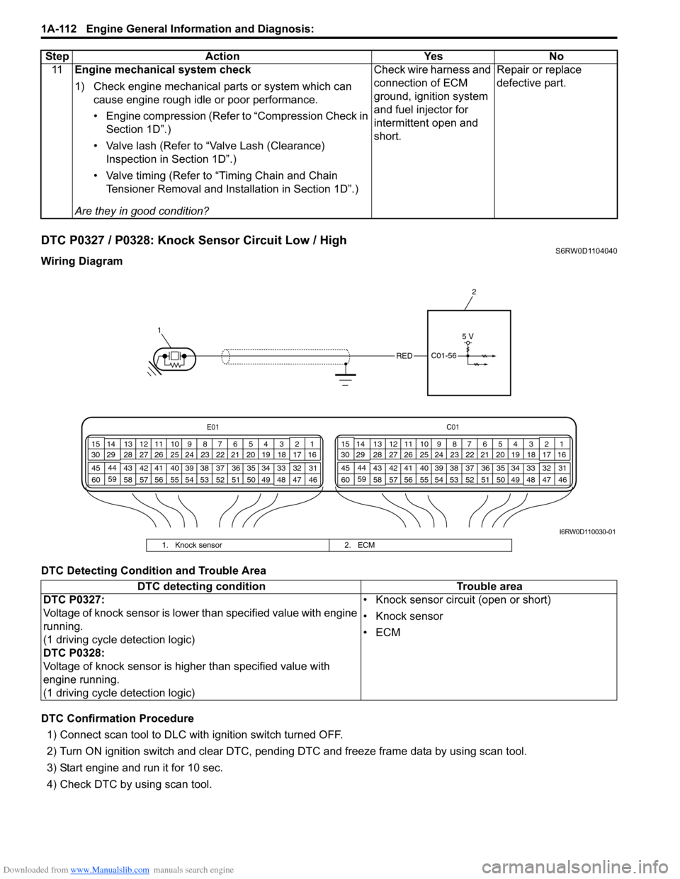
DTC P0327 / P0328: Knock Sensor Circuit Low / HighS6RW0D1104040
Wiring Diagram
DTC Detecting Condition and Trouble Area
DTC Confirmation Procedure
1) Connect scan tool to DLC with ignition switch turned OFF.
2) Turn ON ignition switch and clear DTC, pending DTC and freeze frame data by using scan tool.
3) Start engine and run it for 10 sec.
4) Check DTC by using scan tool.11Engine mechanical system check
1) Check engine mechanical parts or system which can
cause engine rough idle or poor performance.
• Engine compression (Refer to “Compression Check in
Section 1D”.)
• Valve lash (Refer to “Valve Lash (Clearance)
Inspection in Section 1D”.)
• Valve timing (Refer to “Timing Chain and Chain
Tensioner Removal and Installation in Section 1D”.)
Are they in good condition?Check wire harness and
connection of ECM
ground, ignition system
and fuel injector for
intermittent open and
short.Repair or replace
defective part. Step Action Yes No
E01C01
3 4
18 19 5 6 7 10 11
17 20
47 46 49 50 51 21 22
5216 259
24 14
29
55 57 54 53 59
60 582
26 27 28 15
30
56 4832 31 34 35 36 37 40 42 39 38 44
45 43 41 331 12 13
238 3 4
18 19 5 6 7 10 11
17 20
47 46 49 50 51 21 22
5216 259
24 14
29
55 57 54 53 59
60 582
26 27 28 15
30
56 4832 31 34 35 36 37 40 42 39 38 44
45 43 41 331 12 13
238
12
REDC01-56
5 V
I6RW0D110030-01
1. Knock sensor 2. ECM
DTC detecting condition Trouble area
DTC P0327:
Voltage of knock sensor is lower than specified value with engine
running.
(1 driving cycle detection logic)
DTC P0328:
Voltage of knock sensor is higher than specified value with
engine running.
(1 driving cycle detection logic)• Knock sensor circuit (open or short)
• Knock sensor
•ECM
Page 223 of 1556

Downloaded from www.Manualslib.com manuals search engine Engine General Information and Diagnosis: 1A-173
Terminal
No.Wire
colorCircuit Normal voltage Condition Remarks
C01-1BLU/
YELFuel injector No.1
output10 – 14 V Ignition switch turned ON. —
*0 – 0.6 V
↑↓
10 – 14 V
(“Reference
waveform No.1: ”,
“Reference waveform
No.2: ” and
“Reference waveform
No.28: ”)Engine running at idle
after warmed up engine.Output signal is active low
pulse. Pulse frequency
varies depending on
engine speed.
C01-2BLU/
WHTFuel injector No.2
output10 – 14 V Ignition switch turned ON. —
*0 – 0.6 V
↑↓
10 – 14 V
(“Reference
waveform No.1: ” and
“Reference waveform
No.3: ”)Engine running at idle
after warmed up engine.Output signal is active low
pulse. Pulse frequency
varies depending on
engine speed.
C01-3GRN/
ORNEGR valve
(stepper motor coil
2) output (if
equipped)10 – 14 V Ignition switch turned ON. —
*0 – 1 V
↑↓
10 – 14 V
(“Reference
waveform No.4: ”)Ignition switch is turned to
ST (cranking) position.Output signal is active low
duty pulse. Number of
pulse generated times
varies depending on
vehicle condition.
C01-4GRN/
REDEGR valve
(stepper motor coil
1) output (if
equipped)10 – 14 V Ignition switch turned ON. —
*0 – 1 V
↑↓
10 – 14 V
(“Reference
waveform No.4: ”)Ignition switch is turned to
ST (cranking) position.Output signal is active low
duty pulse. Number of
pulse generated times
varies depending on
vehicle condition.
C01-5GRN/
WHTIgnition coil No.2
and No.3 output0 – 0.6 V Ignition switch turned ON. —
*0 – 0.6 V
↑↓
3 – 5 V
(“Reference
waveform No.5: ” and
“Reference waveform
No.6: ”)Engine running at idle
after warmed up engine.Output signal is active
high pulse. Pulse
frequency varies
depending on engine
speed.
C01-6GRN/
YELIgnition coil No.1
and No.4 output0 – 0.6 V Ignition switch turned ON. —
*0 – 0.6 V
↑↓
3 – 5 V
(“Reference
waveform No.6: ”,
“Reference waveform
No.7: ” and
“Reference waveform
No.28: ”)Engine running at idle
after warmed up engine.Output signal is active
high pulse. Pulse
frequency varies
depending on engine
speed.
C01-7 — — — — —
C01-8 — — — — —
C01-9 — — — — —
Page 224 of 1556
Downloaded from www.Manualslib.com manuals search engine 1A-174 Engine General Information and Diagnosis:
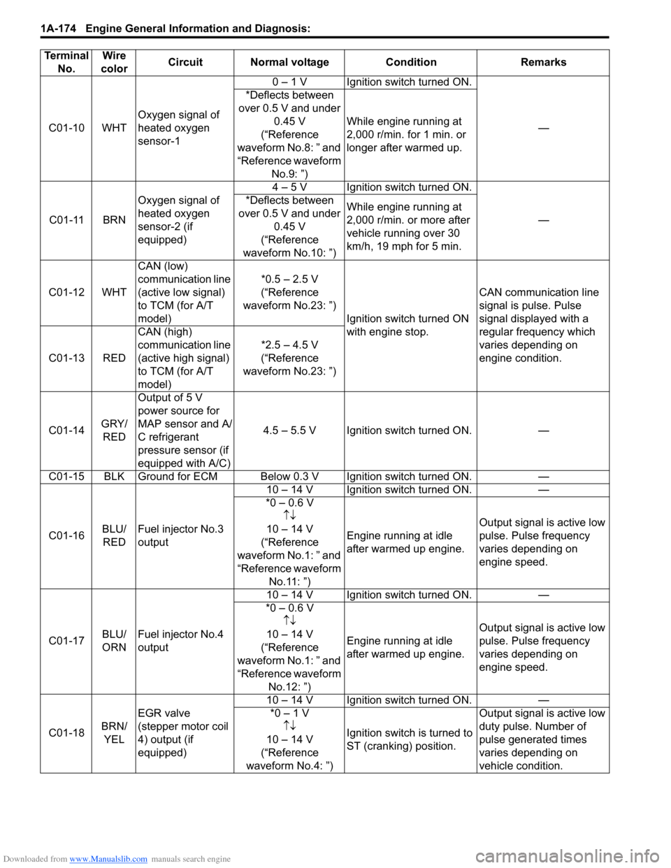
C01-10 WHTOxygen signal of
heated oxygen
sensor-10 – 1 V Ignition switch turned ON.
— *Deflects between
over 0.5 V and under
0.45 V
(“Reference
waveform No.8: ” and
“Reference waveform
No.9: ”)While engine running at
2,000 r/min. for 1 min. or
longer after warmed up.
C01-11 BRNOxygen signal of
heated oxygen
sensor-2 (if
equipped)4 – 5 V Ignition switch turned ON.
— *Deflects between
over 0.5 V and under
0.45 V
(“Reference
waveform No.10: ”)While engine running at
2,000 r/min. or more after
vehicle running over 30
km/h, 19 mph for 5 min.
C01-12 WHTCAN (low)
communication line
(active low signal)
to TCM (for A/T
model)*0.5 – 2.5 V
(“Reference
waveform No.23: ”)
Ignition switch turned ON
with engine stop.CAN communication line
signal is pulse. Pulse
signal displayed with a
regular frequency which
varies depending on
engine condition. C01-13 REDCAN (high)
communication line
(active high signal)
to TCM (for A/T
model)*2.5 – 4.5 V
(“Reference
waveform No.23: ”)
C01-14GRY/
REDOutput of 5 V
power source for
MAP sensor and A/
C refrigerant
pressure sensor (if
equipped with A/C)4.5 – 5.5 V Ignition switch turned ON. —
C01-15 BLK Ground for ECM Below 0.3 V Ignition switch turned ON. —
C01-16BLU/
REDFuel injector No.3
output10 – 14 V Ignition switch turned ON. —
*0 – 0.6 V
↑↓
10 – 14 V
(“Reference
waveform No.1: ” and
“Reference waveform
No.11: ”)Engine running at idle
after warmed up engine.Output signal is active low
pulse. Pulse frequency
varies depending on
engine speed.
C01-17BLU/
ORNFuel injector No.4
output10 – 14 V Ignition switch turned ON. —
*0 – 0.6 V
↑↓
10 – 14 V
(“Reference
waveform No.1: ” and
“Reference waveform
No.12: ”)Engine running at idle
after warmed up engine.Output signal is active low
pulse. Pulse frequency
varies depending on
engine speed.
C01-18BRN/
YELEGR valve
(stepper motor coil
4) output (if
equipped)10 – 14 V Ignition switch turned ON. —
*0 – 1 V
↑↓
10 – 14 V
(“Reference
waveform No.4: ”)Ignition switch is turned to
ST (cranking) position.Output signal is active low
duty pulse. Number of
pulse generated times
varies depending on
vehicle condition. Terminal
No.Wire
colorCircuit Normal voltage Condition Remarks
Page 231 of 1556
Downloaded from www.Manualslib.com manuals search engine Engine General Information and Diagnosis: 1A-181
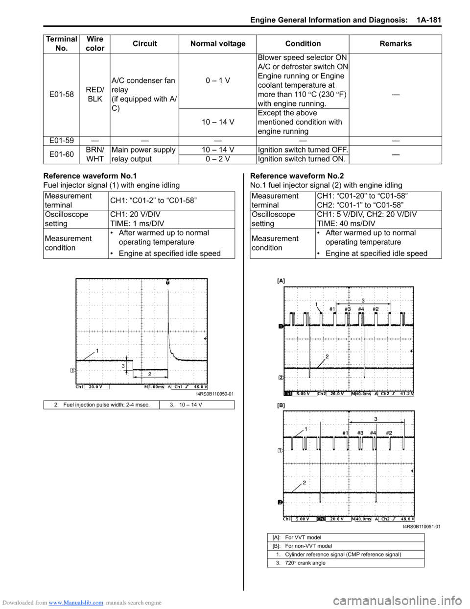
Reference waveform No.1
Fuel injector signal (1) with engine idlingReference waveform No.2
No.1 fuel injector signal (2) with engine idling E01-58RED/
BLKA/C condenser fan
relay
(if equipped with A/
C)0 – 1 VBlower speed selector ON
A/C or defroster switch ON
Engine running or Engine
coolant temperature at
more than 110 °C (230 °F)
with engine running.—
10 – 14 VExcept the above
mentioned condition with
engine running
E01-59 — — — — —
E01-60BRN/
WHTMain power supply
relay output10 – 14 V Ignition switch turned OFF.
—
0 – 2 V Ignition switch turned ON. Terminal
No.Wire
colorCircuit Normal voltage Condition Remarks
Measurement
terminalCH1: “C01-2” to “C01-58”
Oscilloscope
settingCH1: 20 V/DIV
TIME: 1 ms/DIV
Measurement
condition• After warmed up to normal
operating temperature
• Engine at specified idle speed
2. Fuel injection pulse width: 2-4 msec. 3. 10 – 14 V
I4RS0B110050-01
Measurement
terminalCH1: “C01-20” to “C01-58”
CH2: “C01-1” to “C01-58”
Oscilloscope
settingCH1: 5 V/DIV, CH2: 20 V/DIV
TIME: 40 ms/DIV
Measurement
condition• After warmed up to normal
operating temperature
• Engine at specified idle speed
[A]: For VVT model
[B]: For non-VVT model
1. Cylinder reference signal (CMP reference signal)
3. 720° crank angle
I4RS0B110051-01
Page 232 of 1556

Downloaded from www.Manualslib.com manuals search engine 1A-182 Engine General Information and Diagnosis:
Reference waveform No.3
No.2 fuel injector signal (2) with engine idlingReference waveform No.4
EGR valve signal
Measurement
terminalCH1: “C01-20” to “C01-58”
CH2: “C01-2” to “C01-58”
Oscilloscope
settingCH1: 5 V/DIV, CH2: 20 V/DIV
TIME: 40 ms/DIV
Measurement
condition• After warmed up to normal
operating temperature
• Engine at specified idle speed
[A]: For VVT model
[B]: For non-VVT model
1. Cylinder reference signal (CMP reference signal)
3. 720° crank angle
I4RS0B110052-01
Measurement
terminalCH1: “C01-4” to “C01-58”
CH2: “C01-3” to “C01-58”
CH3: “C01-19” to “C01-58”
CH4: “C01-18” to “C01-58”
Oscilloscope
settingCH1: 20 V/DIV, CH2: 20 V/DIV
CH3: 20 V/DIV, CH4: 20 V/DIV
TIME: 40 ms/DIV
Measurement
conditionEngine at cranking
1. EGR valve stepper motor coil 1 signal
2. EGR valve stepper motor coil 2 signal
3. EGR valve stepper motor coil 3 signal
4. EGR valve stepper motor coil 4 signal
5. ON signal
6. OFF signal
I4RS0B110053-01
Page 235 of 1556

Downloaded from www.Manualslib.com manuals search engine Engine General Information and Diagnosis: 1A-185
Reference waveform No.11
No.3 fuel injector signal (2) with engine idlingReference waveform No.12
No.4 fuel injector signal (2) with engine idling
Measurement
terminalCH1: “C01-20” to “C01-58”
CH2: “C01-16” to “C01-58”
Oscilloscope
settingCH1: 5 V/DIV, CH2: 20 V/DIV
TIME: 40 ms/DIV
Measurement
condition• After warmed up to normal
operating temperature
• Engine at specified idle speed
[A]: For VVT model
[B]: For non-VVT model
1. Cylinder reference signal (CMP reference signal)
3. 720° crank angle
I4RS0B110062-01
Measurement
terminalCH1: “C01-20” to “C01-58”
CH2: “C01-17” to “C01-58”
Oscilloscope
settingCH1: 5 V/DIV, CH2: 20 V/DIV
TIME: 40 ms/DIV
Measurement
condition• After warmed up to normal
operating temperature
• Engine at specified idle speed
[A]: For VVT model
[B]: For non-VVT model
1. Cylinder reference signal (CMP reference signal)
3. 720° crank angle
I4RS0B110063-01
Page 241 of 1556

Downloaded from www.Manualslib.com manuals search engine Engine General Information and Diagnosis: 1A-191
Reference waveform No.28
Ignition coil signal and fuel injector signal with engine
crankingReference waveform No.29
Throttle position sensor main (1) and sub (2) signal
Reference waveform No.30
Pedal position sensor main (1) and sub (2) signal Measurement
terminalCH1: “C01-20” to “C01-58”
CH2: “C01-6” to “C01-58”
CH3: “C01-1” to “C01-58”
CH4: “C01-48” to “C01-58”
Oscilloscope
settingCH1: 5 V/DIV, CH2: 5 V/DIV
CH3: 50 V/DIV, CH4: 10 V/DIV
TIME: 200 ms/DIV
Measurement
condition• After warmed up to normal
operating temperature
• Engine at cranking
[A]: For VVT model
[B]: For non-VVT model
1. Cylinder reference signal (CMP reference signal)
2. Ignition coil No.1 and No.4 signal
3. No.1 fuel injector signal
4. Engine start signal
I4RS0B110083-01
Measurement
terminalCH1: “C01-54” to “C01-58”
CH2: “C01-40” to “C01-58”
Oscilloscope
settingCH1: 1 V/DIV, CH2: 1 V/DIV
TIME: 200 ms/DIV
Measurement
condition• After warmed up to normal
operating temperature
• Ignition switch turned ON and
depress accelerator pedal fully
3. Accelerator pedal released
4. Accelerator pedal depressed fully
Measurement
terminalCH1: “E01-37” to “C01-58”
CH2: “E01-36” to “C01-58”
Oscilloscope
settingCH1: 1 V/DIV, CH2: 1 V/DIV
TIME: 100 ms/DIV
Measurement
condition• After warmed up to normal
operating temperature
• Ignition switch turned ON and
depress accelerator pedal fully
3. Accelerator pedal released
4. Accelerator pedal depressed fully
3431
2
I5RW0C110023-01
3431
2
I5RW0C110024-01
Page 242 of 1556

Downloaded from www.Manualslib.com manuals search engine 1A-192 Engine General Information and Diagnosis:
Resistance Check
1) Remove ECM from its bracket referring to “Engine Control Module (ECM) Removal and Installation in Section 1C”.
CAUTION!
Never touch terminals of ECM itself or connect voltmeter or ohmmeter (2).
2) Connect special tool to ECM connectors (1) securely.
NOTE
Do not connect the other connector of special tool to ECM.
Special tool
(A): 09933–06320
3) Check resistance between each pair of terminals of special tool connectors (1) as listed in the following table.
CAUTION!
• Be sure to connect ohmmeter probe from wire harness side of coupler.
• Be sure to turn OFF ignition switch for this check.
• Resistance in the following table represents that measured when parts temperature is 20 °C (68 °F).
1
(A)
2
3
I7RW01110032-02
Terminals Circuit Standard resistance Condition
C01-47 to E01-29 Heater of HO2S-2 4 – 15 Ω—
E01-46 to E01-1/16 Radiator cooling fan relay No.1 160 – 240 Ω—
E01-60 to E01-29 Main relay 160 – 240 ΩBattery disconnected and
ignition switch turned ON
E01-15 to E01-29 Fuel pump relay 160 – 240 Ω—
C01-16 to E01-1/16No.3 fuel injector
10.8 – 18.2 Ω—
C01-17 to E01-1/16No.4 fuel injector
C01-4 to E01-1/16EGR valve (stepping motor No.1 coil) (if
equipped)20 – 31 Ω—
C01-29 to E01-1/16 EVAP canister purge valve 28 – 35 Ω—
C01-2 to E01-1/16 No.2 fuel injector 10.8 – 18.2 Ω—
C01-3 to E01-1/16EGR valve (stepping motor No.2 coil) (if
equipped)
20 – 31 Ω— C01-18 to E01-1/16EGR valve (stepping motor No.4 coil) (if
equipped)
C01-19 to E01-1/16EGR valve (stepping motor No.3 coil) (if
equipped)
C01-46 to E01-29 Heater of HO2S-1 2 – 11 Ω—
C01-1 to E01-1/16 No.1 fuel injector 10.8 – 18.2 Ω—
E01-29 to E01-47 A/C compressor relay (if equipped with A/C) 160 – 240 Ω—
E01-58 to E01-1/16A/C condenser cooling fan relay
(if equipped with A/C)160 – 240 Ω—
C01-60 to C01-59 Oil control valve (for engine with VVT system) 6 – 15 Ω—
E01-45 to E01-1/16 Throttle actuator control relay 160 – 240 Ω—
Page 246 of 1556
Downloaded from www.Manualslib.com manuals search engine 1A-196 Engine General Information and Diagnosis:
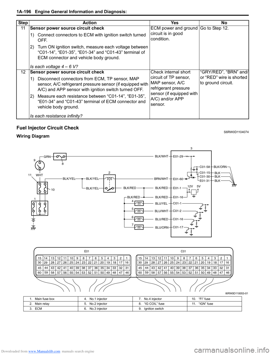
Fuel Injector Circuit CheckS6RW0D1104074
Wiring Diagram11Sensor power source circuit check
1) Connect connectors to ECM with ignition switch turned
OFF.
2) Turn ON ignition switch, measure each voltage between
“C01-14”, “E01-35”, “E01-34” and “C01-43” terminal of
ECM connector and vehicle body ground.
Is each voltage 4 – 6 V?ECM power and ground
circuit is in good
condition.Go to Step 12.
12Sensor power source circuit check
1) Disconnect connectors from ECM, TP sensor, MAP
sensor, A/C refrigerant pressure sensor (if equipped with
A/C) and APP sensor with ignition switch turned OFF.
2) Measure each resistance between “C01-14”, “E01-35”,
“E01-34” and “C01-43” terminal of ECM connector and
vehicle body ground.
Is each resistance infinity?Check internal short
circuit of TP sensor,
MAP sensor, A/C
refrigerant pressure
sensor (if equipped with
A/C) and/or APP
sensor.“GRY/RED”, “BRN” and/
or “RED” wire is shorted
to ground circuit. Step Action Yes No
BLK/WHT
BLK/RED
BLK/RED
WHTBLK/YELBLK/YEL
BLK/YEL
GRN
BRN/WHT
12V5V
9
2 83E01-29
E01-1
E01-60
10 11
E01C01
3 4
18 19 5 6 7 10 11
17 20
47 46 49 50 51 21 22
5216 259
24 14
29
55 57 54 53 59
60 582
26 27 28 15
30
56 4832 31 34 35 36 37 40 42 39 38 44
45 43 41 331 12 13
238 3 4
18 19 5 6 7 10 11
17 20
47 46 49 50 51 21 22
5216 259
24 14
29
55 57 54 53 59
60 582
26 27 28 15
30
56 4832 31 34 35 36 37 40 42 39 38 44
45 43 41 331 12 13
238
C01-1
C01-2
C01-16
C01-17
BLK/REDBLK/RED
BLU/YEL
BLU/RED
BLU/ORN
BLU/WHT
E01-16
4
5
6
71
C01-58
C01-15 C01-30
BLK/ORN
BLKBLKBLKE01-31
I6RW0D110053-01
1. Main fuse box 4. No.1 injector 7. No.4 injector 10. “FI” fuse
2. Main relay 5. No.2 injector 8. “IG COIL” fuse 11. “IGN” fuse
3. ECM 6. No.3 injector 9. Ignition switch