check engine SUZUKI SX4 2006 1.G Service Workshop Manual
[x] Cancel search | Manufacturer: SUZUKI, Model Year: 2006, Model line: SX4, Model: SUZUKI SX4 2006 1.GPages: 1556, PDF Size: 37.31 MB
Page 540 of 1556

Downloaded from www.Manualslib.com manuals search engine 3B-43 Differential:
19) Using special tool and plastic hammer, drive oil seal
(2) into differential carrier (1) as shown in figure.
Then apply grease to oil seal lip.
NOTE
Install oil seal horizontally to surface of
differential carrier.
“A”: Grease 99000–25010 (SUZUKI Super
Grease A)
Distance between differential carrier and oil seal
“a”
: 0.5 – 1.5 mm (0.02 – 0.06 in.)
Special tool
(A): 09913–85210
20) Tighten bevel pinion nut (1) gradually with special
tool to specified torque while turning bevel pinion.
Set bearing preload of bevel pinion to specification.
NOTE
• Before taking measurement with torque
wrench, check for smooth rotation with
turning bevel pinion 15 revolutions or
more by hand.
• Be sure to tighten gradually and carefully
till specified pinion bearing preload is
obtained. Turning back overtightened
flange nuts should be avoided.
• Measure pinion bearing preload while
turning bevel pinion about 50 rpm.
• Write down measured value of bevel pinion
bearing preload for differential side
bearing shim adjustment.
Special tool
(A): 09927–27910
Tightening torque
Bevel pinion nut: 230 – 340 N·m (23.0 – 34.0 kgf-
m, 166.5 – 246.0 lb-ft)
Bevel pinion bearing preload (Bevel pinion
rotational torque)
: 1.3 – 2.6 N⋅m (13.0 – 26.0 kgf-cm, 11.3 – 22.6 lb-
in.)
21) Install differential case assembly, bearing outer
races, removed shim and differential cover,
temporarily.
NOTE
• Used left and right outer races are not
interchangeable.
• When measuring bevel pinion bearing
preload, install differential cover with
sealant not applied.
22) Select differential side bearing shim so that bevel
pinion bearing preload may be specified value.
NOTE
Select shims so that thickness of right side
shims and left side shims become almost
even.
Bevel pinion bearing preload
Preload measured in Step 20) + 0.3 – 0.7 N⋅m (3 –
7 kgf-cm, 2.6 – 6.0 lb-in.)
Available shim thickness
0.45, 2.30, 2.35, 2.40, 2.45, 2.50, 2.55, 2.60, 2.65
and 2.70 mm (0.017, 0.090, 0.092, 0.094, 0.096,
0.098, 0.100, 0.102, 0.104 and 0.106 in.)
(A)
11
2, “A”
“a”
I5RW0A320054-02
(A)
1
I5RW0A320055-03
I5RW0A320056-01
Page 541 of 1556

Downloaded from www.Manualslib.com manuals search engine Differential: 3B-44
23) Remove differential cover.
24) To measure bevel gear backlash, set dial gauge at
right angle to bevel gear tooth, fix drive bevel pinion
and read dial gauge while moving bevel gear.
If bevel gear backlash is out of specification, repeat
Step 22).
NOTE
• Be sure to apply measuring tip of dial
gauge at right angles to convex side of
tooth.
• Measure at least 4 points on drive bevel
gear periphery.
Drive bevel gear back lash
0.1 – 0.2 mm (0.004 – 0.008 in.)Special tool
(A): 09900–20607
(B): 09900–20701
25) As final step, check gear tooth contact as follows.
a) After cleaning 10 drive bevel gear teeth, paint them with gear marking compound evenly by using brush (1) or
sponge etc.
b) Turn gear to bring its painted part in mesh with drive bevel pinion and turn it back and forth by hand to repeat
their contact.
c) Bring painted part up and check contact pattern, referring to the following table. If contact pattern is not normal,
readjust or replace as necessary according to instruction in the table.
NOTE
Be careful not to turn drive bevel gear more than one full revolution, for it will hinder accurate check.
I5RW0A320057-01
A: Paint gear marking compound evenly
1
A
I5JB0A321040-02
Page 542 of 1556

Downloaded from www.Manualslib.com manuals search engine 3B-45 Differential:
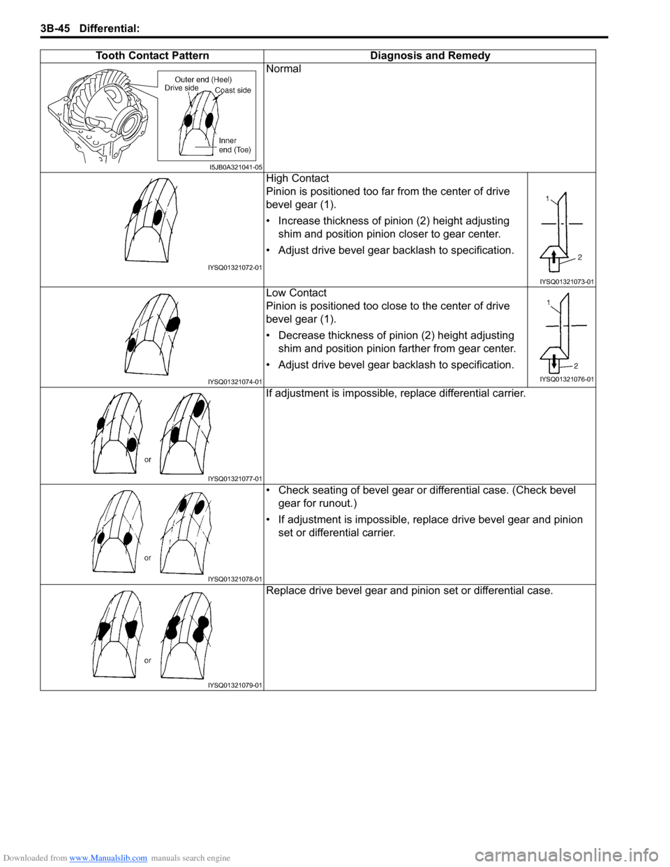
Tooth Contact Pattern Diagnosis and Remedy
Normal
High Contact
Pinion is positioned too far from the center of drive
bevel gear (1).
• Increase thickness of pinion (2) height adjusting
shim and position pinion closer to gear center.
• Adjust drive bevel gear backlash to specification.
Low Contact
Pinion is positioned too close to the center of drive
bevel gear (1).
• Decrease thickness of pinion (2) height adjusting
shim and position pinion farther from gear center.
• Adjust drive bevel gear backlash to specification.
If adjustment is impossible, replace differential carrier.
• Check seating of bevel gear or differential case. (Check bevel
gear for runout.)
• If adjustment is impossible, replace drive bevel gear and pinion
set or differential carrier.
Replace drive bevel gear and pinion set or differential case.
I5JB0A321041-05
IYSQ01321072-01
IYSQ01321073-01
IYSQ01321074-01IYSQ01321076-01
IYSQ01321077-01
IYSQ01321078-01
IYSQ01321079-01
Page 544 of 1556

Downloaded from www.Manualslib.com manuals search engine 3B-47 Differential:
31) Clean mating surface of differential carrier (1) and
coupling case (2), apply sealant to carrier as shown
in figure by such amount that its section is 1.5 mm
(0.059 in.) in diameter, mate coupling case with
differential carrier as shown in figure, and then
tighten bolts to specified torque.
“A”: Sealant 99000–31260 (SUZUKI Bond
No.1217G)
Tightening torque
Coupling case bolt (a): 23 N·m (2.3 kgf-m, 17.0
lb-ft)
NOTE
Install coupling pin (3) by fitting it to groove
(4) of coupling case.
32) Apply grease to oil seal lip, and then install oil seals
(1) to rear differential (2) using special tool as shown
in figure.
NOTE
Install oil seal horizontally to surface of rear
differential case.
“A”: Grease 99000–25010 (SUZUKI Super
Grease A)
Distance between rear differential and oil seal
“a”
: 1.0 – 2.0 mm (0.04 – 0.08 in.)
Special tool
(A): 09913–75810
33) Install drive shaft flange.
34) Install rear mounting bracket to rear differential
referring to “Front Mounting Arm and/or Rear
Mounting Bracket Assembly Removal and
Installation”.
Rear Differential InspectionS6RW0D3206015
• Check companion flange for wear or damage.
• Check bearings for wear or discoloration.
• Check differential carrier for cracks.
• Check drive bevel pinion and bevel gear for wear or
cracks.
• Check side gears, pinion gears and pinion shaft for
wear or damage.
• Check side gear spline for wear or damage.
1 4
3 2“A”
(a)
I5RW0A320062-04
(A)
2 21, “A”
“a”
I5RW0A320063-02
Page 549 of 1556

Downloaded from www.Manualslib.com manuals search engine Transfer: 3C-2
Repair Instructions
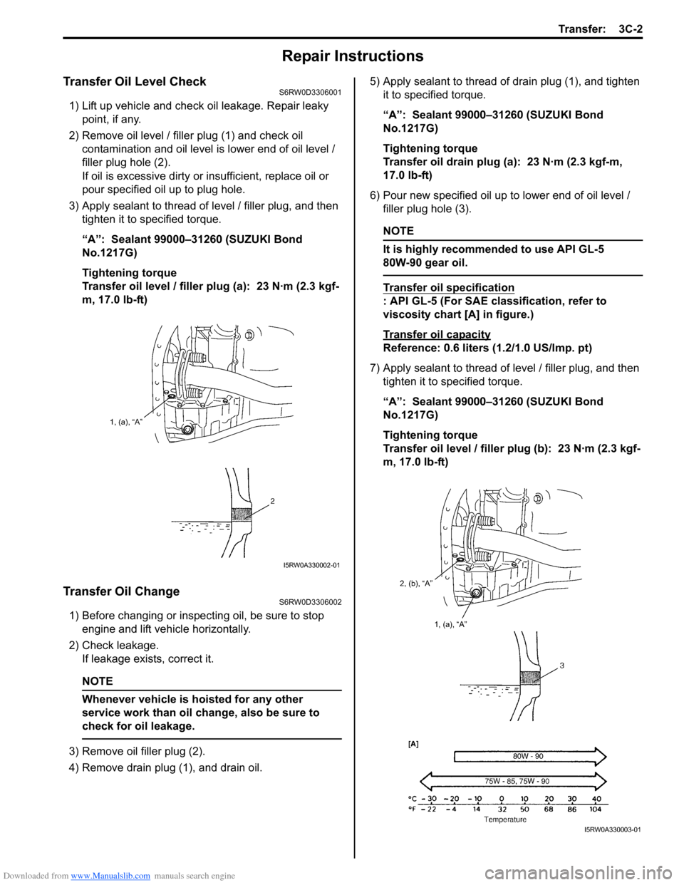
Transfer Oil Level CheckS6RW0D3306001
1) Lift up vehicle and check oil leakage. Repair leaky
point, if any.
2) Remove oil level / filler plug (1) and check oil
contamination and oil level is lower end of oil level /
filler plug hole (2).
If oil is excessive dirty or insufficient, replace oil or
pour specified oil up to plug hole.
3) Apply sealant to thread of level / filler plug, and then
tighten it to specified torque.
“A”: Sealant 99000–31260 (SUZUKI Bond
No.1217G)
Tightening torque
Transfer oil level / filler plug (a): 23 N·m (2.3 kgf-
m, 17.0 lb-ft)
Transfer Oil ChangeS6RW0D3306002
1) Before changing or inspecting oil, be sure to stop
engine and lift vehicle horizontally.
2) Check leakage.
If leakage exists, correct it.
NOTE
Whenever vehicle is hoisted for any other
service work than oil change, also be sure to
check for oil leakage.
3) Remove oil filler plug (2).
4) Remove drain plug (1), and drain oil.5) Apply sealant to thread of drain plug (1), and tighten
it to specified torque.
“A”: Sealant 99000–31260 (SUZUKI Bond
No.1217G)
Tightening torque
Transfer oil drain plug (a): 23 N·m (2.3 kgf-m,
17.0 lb-ft)
6) Pour new specified oil up to lower end of oil level /
filler plug hole (3).
NOTE
It is highly recommended to use API GL-5
80W-90 gear oil.
Transfer oil specification
: API GL-5 (For SAE classification, refer to
viscosity chart [A] in figure.)
Transfer oil capacity
Reference: 0.6 liters (1.2/1.0 US/lmp. pt)
7) Apply sealant to thread of level / filler plug, and then
tighten it to specified torque.
“A”: Sealant 99000–31260 (SUZUKI Bond
No.1217G)
Tightening torque
Transfer oil level / filler plug (b): 23 N·m (2.3 kgf-
m, 17.0 lb-ft)
I5RW0A330002-01
I5RW0A330003-01
Page 559 of 1556

Downloaded from www.Manualslib.com manuals search engine Transfer: 3C-12
c) Tighten bevel pinion nut (special tool) so that
specified bearing preload is obtained.
NOTE
Before taking measurement, check for
rotation by hand more than 15 revolutions.
Tightening torque
Rotational torque of bevel pinion (Bearing
preload): 0.50 – 1.30 N·m (0.05 – 0.13 kgf-m,
0.35 – 0.95 lb-ft)
d) Measure height “b” in figure by using vernier
caliper.
Calculate “c” by using measured value.e) Obtain adjusting shim thickness by the following
equation.
f) Select a shim closest to the calculated value
(necessary shim thickness) from among the
available shims or combine shims to become
closest to calculated value.
For example:
Measure distance “b” is 69.95 mm (2.754 in.).
“c” = 69.95 mm (2.754 in.) – 40.0 mm (1.757 in.)
= 29.95 mm (1.179 in.)
“f” = 29.95 mm (1.179 in.) + 74.0 mm (2.913 in.)
– 101.95 mm (4.014 in.) = 2.0 mm (0.079 in.)
Calculated thickness of new shim = 2.0 mm
(0.079 in.)
Available bevel pinion shim thickness
0.30, 1.85, 1.88, 1.91, 1.94, 1.97, 2.00, 2.03,
2.06, 2.09, 2.12 and 2.15 mm (0.012, 0.072,
0.074, 0.075, 0.076, 0.077, 0.078, 0.079, 0.081,
0.082, 0.083 and 0.084 in.) Distance “c” = Height “b” –Height “a” 40 mm
(1.575 in.)
I5RW0A330036-02
“a”
“b”
“c”
I5RW0A330046-01
Necessary
shim
thickness “f”=Distance
“c”+Distance
“d”
–Distance
“e”
74.0 mm
(2.913 in.)101.95 mm
(4.014 in.)
“d”: Pinion shaft mounting distance 74.0 mm (2.913 in.)
“e”: Distance from end face of left case to axis of reduction driven gear
101.95 mm (4.014 in.)
“f”: Necessary shim thickness
“d” “e”
“f ”
I5RW0A330037-01
Page 561 of 1556

Downloaded from www.Manualslib.com manuals search engine Transfer: 3C-14
8) Install transfer output flange (1) by tapping with
plastic hammer and tighten transfer output flange nut
gradually so as rotational torque of bevel pinion to be
in specified value.
NOTE
• If rotational torque of bevel pinion exceeds
specification given in the following,
replace pinion shaft spacers and tighten
flange nut.
• Before taking measurement of rotational
torque, rotate pinion over ten rounds in
advance.
Bevel pinion bearing preload
: 0.5 – 1.3 N⋅m (0.05 – 0.13 kgf-m, 0.35 – 0.95 lb-ft)
Special tool
(A): 09930–40113
9) Caulk transfer output flange nut (1).
Transfer Assembly InspectionS6RW0D3306010
• Check each bearing for smooth rotation, wear or
discoloration
If found abnormal, replace.
• Check oil seal for leakage and its lip for excessive
hardness
If either is found, replace.
• Check transfer case for cracks.
• Check bevel pinion and bevel gears for wear or
cracks.
Bevel Gear Tooth Contact InspectionS6RW0D3306011
1) After cleaning tooth surface of bevel gear (1), paint
them with gear marking compound evenly by using
brush or sponge etc.
NOTE
When applying red lead paste to teeth, be
sure to paint tooth surfaces uniformly. The
paste must not be too dry or too fluid.
2) Install transfer output retainer assembly referring to
“Transfer Assembly Disassembly and Reassembly”.
3) Turn transfer output flange clockwise and
counterclockwise repeatedly, and remove transfer
output retainer assembly and bevel gear shims from
transfer assembly.
2. Torque wrench
(A)1
2
I5RW0A330043-01
1
I5RW0A330044-01
I3RH01332043-01
Page 562 of 1556

Downloaded from www.Manualslib.com manuals search engine 3C-15 Transfer:
4) Bring painted part up and check contact pattern referring to the following chart. If contact pattern is not normal,
readjust or replace as necessary according to instruction in chart.
NOTE
• Be careful not to turn bevel gear more than one full revolution, for it will hinder accurate check.
• If bevel gear back lash and bevel pinion shims are adjusted properly, correct tooth contact should
be provided.
If correct tooth contact is not provided even when they are adjusted properly, however, there may be
an abnormal condition in worn tooth, transfer case or retainer. Check each component and replace
as necessary.
Gear tooth contact table
Tooth contact pattern Diagnosis and remedy
Normal
High contact
Pinion is positioned too far from the center of drive bevel
gear.
• Decrease thickness of bevel pinion shim and position
pinion closer to gear center.
• Adjust drive bevel gear backlash to specification.
Low contact
Pinion is positioned too close to the center of drive bevel
gear.
• Increase thickness of bevel pinion shim and position
pinion farther from gear center.
• Adjust drive bevel gear backlash to specification.
These contact patterns indicate that the “offset” of
reduction driven gear is too much or too little. The
remedy is to change the division of the bevel gear
shim(s).
I5RW0A330045-01
I3RH01332045-01
I3RH01332046-01
I3RH01332047-01
Page 567 of 1556

Downloaded from www.Manualslib.com manuals search engine Propeller Shafts: 3D-2
Repair Instructions
Propeller Shaft Joint CheckS6RW0D3406001
If universal joints and ball joint are suspected of
producing chattering or rattling noise, inspect them for
wear. For universal joint, check to see if cross spider
rattles in yokes are worn down and replace defective
propeller shaft assembly with new one.
Noise coming from universal joint and ball joint can be
easily distinguished from other noises because rhythm
of chattering or rattling is in step with cruising speed.
Noise is pronounced particularly on standing start or in
coasting condition (when braking effect of engine is
showing in the drive line).
Propeller Shaft Assembly Removal and
Installation
S6RW0D3406002
Removal
1) Hoist vehicle.
2) Before removing propeller shaft assembly, give
match marks (2) on joint flange and propeller shaft
as shown.
3) Separate propeller shaft assembly (1) from transfer
output flange and rear differential flange.4) Remove propeller shaft by removing center support
nuts (1).
CAUTION!
Use care not to drop it. Otherwise, vibration
may occur during driving.
Installation
Reverse removal procedure to install propeller shaft,
noting the following point.
• When installing propeller shaft, align the match marks
(2). Otherwise, vibration may occur during driving.
• Use the following specification to torque each bolt and
nut.
Tightening torque
Propeller shaft bolt: 23 N·m (2.3 kgf-m, 17.0 lb-ft)
Center support nut: 55 N·m (5.5 kgf-m, 40.0 lb-ft)
Propeller Shaft InspectionS6RW0D3406003
1) Check propeller shaft joints for wear, play and
damage. If any defect is found, replace.
2) Check propeller shaft center support for biting of
foreign matter, crack, abnormal noise and damage. If
any defect is found, replace.
I5JB0A340003-01
2
2
1
1
I5RW0A340002-01
1I5RW0A340003-01
Page 570 of 1556

Downloaded from www.Manualslib.com manuals search engine 4-ii Table of Contents
Specifications .......................................................4D-4
Tightening Torque Specifications ........................4D-4
ABS ............................................................4E-1
Precautions........................................................... 4E-1
Precautions in Diagnosing Troubles ................... 4E-1
Precautions in On-Vehicle Service...................... 4E-1
General Description ............................................. 4E-2
ABS Description .................................................. 4E-2
ABS Hydraulic Unit / Control Module
Assembly Description ....................................... 4E-3
CAN Communication System Description........... 4E-3
Schematic and Routing Diagram ........................ 4E-4
ABS Schematic ................................................... 4E-4
ABS Wiring Circuit Diagram ................................ 4E-5
Component Location ........................................... 4E-8
ABS Components Location ................................. 4E-8
Diagnostic Information and Procedures ............ 4E-8
ABS Check .......................................................... 4E-8
ABS Warning Light Check................................. 4E-10
EBD Warning Light (Brake Warning Light)
Check .............................................................. 4E-10
DTC Check........................................................ 4E-11
DTC Table ......................................................... 4E-11
DTC Clearance ................................................. 4E-11
Scan Tool Data ................................................. 4E-12
ABS Warning Light Does Not Come ON at
Ignition Switch ON .......................................... 4E-13
ABS Warning Light Comes ON Steady ............. 4E-15
EBD Warning Light (Brake Warning Light)
Comes ON Steady .......................................... 4E-16
Serial Data Link Circuit Check .......................... 4E-17
DTC C1013: Control Module Mismatch ............ 4E-20
DTC C1015: G Sensor Circuit (4WD Model)..... 4E-21
DTC 1016: Brake Light Switch .......................... 4E-22
DTC C1021 / C1022 / C1025 / C1026 / C1031
/ C1032 / C1035 / C1036: Wheel Speed
Sensor Circuit / Sensor or Encoder ................ 4E-23
DTC C1033: Wheel Speed Sensor Deviation ... 4E-25
DTC C1041 / C1042 / C1045 / C1046 / C1051
/ C1052 / C1055 / C1056: Inlet / Outlet
Solenoid .......................................................... 4E-26DTC C1057: Power Supply Voltage Too High
/ Too Low ........................................................ 4E-27
DTC C1061: Pump Motor Circuit ...................... 4E-28
DTC C1063: Solenoid Valve Power Supply
Driver Circuit ................................................... 4E-29
DTC C1071: Control Module Internal Defect .... 4E-30
ABS Hydraulic Unit / Control Module
Assembly Power and Ground Circuit Check ... 4E-30
Repair Instructions ............................................ 4E-31
ABS Hydraulic Unit Operation Check................ 4E-31
ABS Hydraulic Unit / Control Module
Assembly Components ................................... 4E-32
ABS Hydraulic Unit / Control Module
Assembly On-Vehicle Inspection .................... 4E-33
ABS Hydraulic Unit / Control Module
Assembly Removal and Installation ................ 4E-33
Front and Rear Wheel Speed Sensor On-
Vehicle Inspection ........................................... 4E-34
Front Wheel Speed Sensor Removal and
Installation ....................................................... 4E-35
Front and Rear Wheel Speed Sensor
Inspection ........................................................ 4E-36
Rear Wheel Speed Sensor Removal and
Installation (4WD Model) ................................. 4E-36
Rear Wheel Speed Sensor Removal and
Installation (2WD Model) ................................. 4E-36
Front Wheel Speed Sensor Encoder On-
Vehicle Inspection ........................................... 4E-37
Front Wheel Speed Sensor Encoder Removal
and Installation ................................................ 4E-37
Rear Wheel Speed Sensor Encoder On-
Vehicle Inspection ........................................... 4E-37
Rear Wheel Speed Sensor Encoder Removal
and Installation ................................................ 4E-37
G Sensor Removal and Installation (4WD
Model) ............................................................. 4E-38
G Sensor Inspection (4WD Model) ................... 4E-38
Specifications ..................................................... 4E-39
Tightening Torque Specifications ...................... 4E-39
Special Tools and Equipment ........................... 4E-39
Special Tool ...................................................... 4E-39