brake sensor SUZUKI SX4 2006 1.G Service Owner's Guide
[x] Cancel search | Manufacturer: SUZUKI, Model Year: 2006, Model line: SX4, Model: SUZUKI SX4 2006 1.GPages: 1556, PDF Size: 37.31 MB
Page 465 of 1556
Downloaded from www.Manualslib.com manuals search engine Rear Suspension: 2C-6
Rear Axle Removal and InstallationS6RW0D2306007
CAUTION!
Do not drop brake fluid onto painted surface.
Painted surfaces will be damaged.
Removal
1) Hoist vehicle and remove exhaust center pipe and
muffler.
2) Disconnect rear height sensor link (if equipped) from
rear axle referring to “Height Sensor Removal and
Installation (If Equipped) in Section 9B”.
3) Remove rear wheel, rear brake drum and rear wheel
hub referring to “Removal” under “Rear Wheel Hub
Assembly Removal and Installation”.
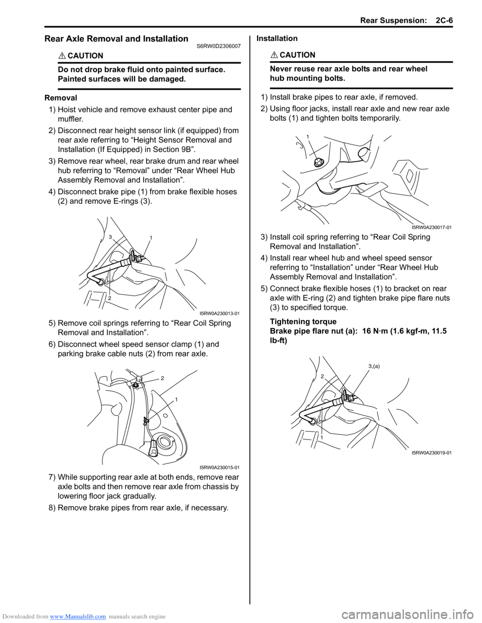
4) Disconnect brake pipe (1) from brake flexible hoses
(2) and remove E-rings (3).
5) Remove coil springs referring to “Rear Coil Spring
Removal and Installation”.
6) Disconnect wheel speed sensor clamp (1) and
parking brake cable nuts (2) from rear axle.
7) While supporting rear axle at both ends, remove rear
axle bolts and then remove rear axle from chassis by
lowering floor jack gradually.
8) Remove brake pipes from rear axle, if necessary.Installation
CAUTION!
Never reuse rear axle bolts and rear wheel
hub mounting bolts.
1) Install brake pipes to rear axle, if removed.
2) Using floor jacks, install rear axle and new rear axle
bolts (1) and tighten bolts temporarily.
3) Install coil spring referring to “Rear Coil Spring
Removal and Installation”.
4) Install rear wheel hub and wheel speed sensor
referring to “Installation” under “Rear Wheel Hub
Assembly Removal and Installation”.
5) Connect brake flexible hoses (1) to bracket on rear
axle with E-ring (2) and tighten brake pipe flare nuts
(3) to specified torque.
Tightening torque
Brake pipe flare nut (a): 16 N·m (1.6 kgf-m, 11.5
lb-ft)
1 3
2
I5RW0A230013-01
2
1
I5RW0A230015-01
1
I5RW0A230017-01
2
1
3,(a)
I5RW0A230019-01
Page 466 of 1556
Downloaded from www.Manualslib.com manuals search engine 2C-7 Rear Suspension:
6) Connect rear height sensor link (if equipped) to rear
axle referring to “Height Sensor Removal and
Installation (If Equipped) in Section 9B”.
7) Install exhaust center pipe and muffler.
8) After installing removed parts, bleed air from brake
system referring to “Air Bleeding of Brake System in
Section 4A”. And then adjust parking brake cable
referring to “Parking Brake Inspection and
Adjustment in Section 4D”.
9) Install wheel and tighten wheel nuts to specified
torque.
Tightening torque
Wheel nut: 85 N·m (8.5 kgf-m, 61.5 lb-ft)
10) Lower hoist and bounce vehicle up and down
several times to stabilize suspension.
11) Tightening shock absorber lower nuts and rear axle
bolts to specified torque.
NOTE
When tightening these nuts and bolts, be
sure that vehicle is not on hoist and in
unloaded condition.
Tightening torque
Rear shock absorber lower nut: 90 N·m (9.0 kgf-
m, 65.0 lb-ft)
Rear axle bolt: 73 N·m (7.3 kgf-m, 53.0 lb-ft)
12) Perform brake test (foot brake and parking brake).
13) Check each installed parts for brake fluid leakage.
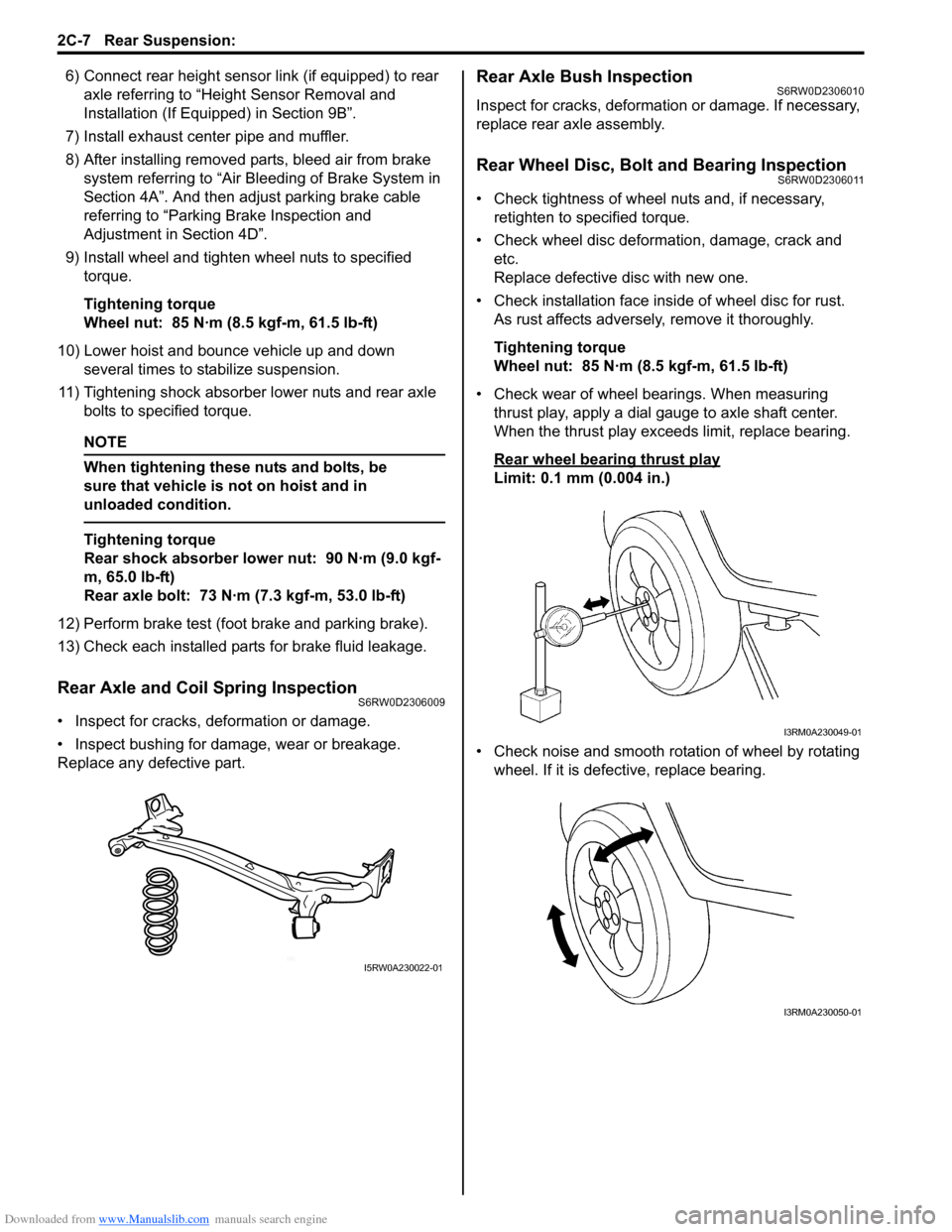
Rear Axle and Coil Spring InspectionS6RW0D2306009
• Inspect for cracks, deformation or damage.
• Inspect bushing for damage, wear or breakage.
Replace any defective part.
Rear Axle Bush InspectionS6RW0D2306010
Inspect for cracks, deformation or damage. If necessary,
replace rear axle assembly.
Rear Wheel Disc, Bolt and Bearing InspectionS6RW0D2306011
• Check tightness of wheel nuts and, if necessary,
retighten to specified torque.
• Check wheel disc deformation, damage, crack and
etc.
Replace defective disc with new one.
• Check installation face inside of wheel disc for rust.
As rust affects adversely, remove it thoroughly.
Tightening torque
Wheel nut: 85 N·m (8.5 kgf-m, 61.5 lb-ft)
• Check wear of wheel bearings. When measuring
thrust play, apply a dial gauge to axle shaft center.
When the thrust play exceeds limit, replace bearing.
Rear wheel bearing thrust play
Limit: 0.1 mm (0.004 in.)
• Check noise and smooth rotation of wheel by rotating
wheel. If it is defective, replace bearing.
(a)I5RW0A230022-01
I3RM0A230049-01
I3RM0A230050-01
Page 467 of 1556
Downloaded from www.Manualslib.com manuals search engine Rear Suspension: 2C-8
Rear Wheel Hub Assembly Removal and
Installation
S6RW0D2306012
CAUTION!
Do not allow brake fluid to get on painted
surfaces. Painted surface will be damaged.
Removal
1) Hoist vehicle. Then remove rear wheel and brake
drum.
2) For 4WD model, remove rear drive shaft referring to
“Rear Drive Shaft Assembly Removal and
Installation in Section 3A”.
3) Remove rear brake shoe.
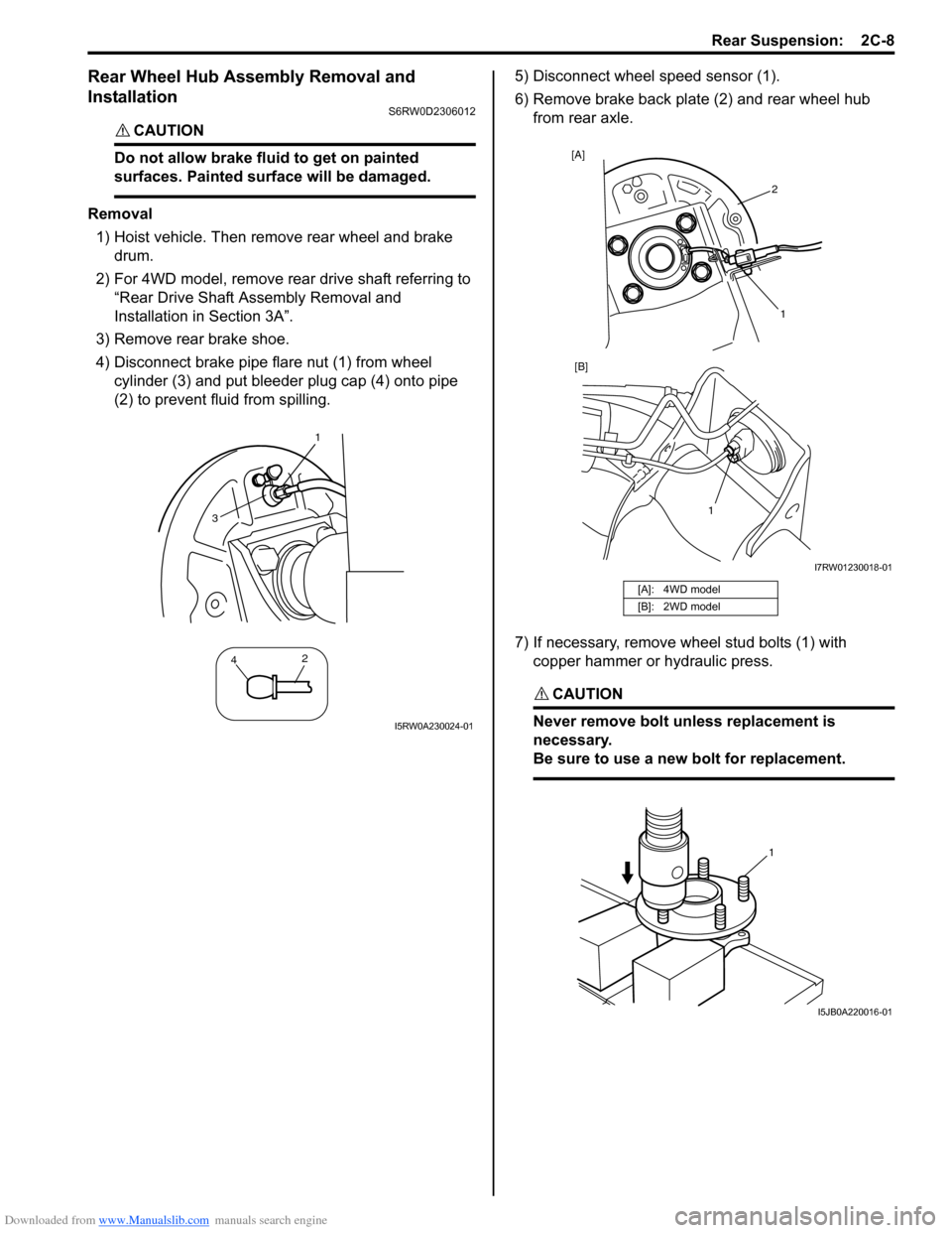
4) Disconnect brake pipe flare nut (1) from wheel
cylinder (3) and put bleeder plug cap (4) onto pipe
(2) to prevent fluid from spilling.5) Disconnect wheel speed sensor (1).
6) Remove brake back plate (2) and rear wheel hub
from rear axle.
7) If necessary, remove wheel stud bolts (1) with
copper hammer or hydraulic press.
CAUTION!
Never remove bolt unless replacement is
necessary.
Be sure to use a new bolt for replacement.
1
42
3
I5RW0A230024-01
[A]: 4WD model
[B]: 2WD model
2 [A]
1 [B]
1
I7RW01230018-01
1
I5JB0A220016-01
Page 468 of 1556
Downloaded from www.Manualslib.com manuals search engine 2C-9 Rear Suspension:
Installation
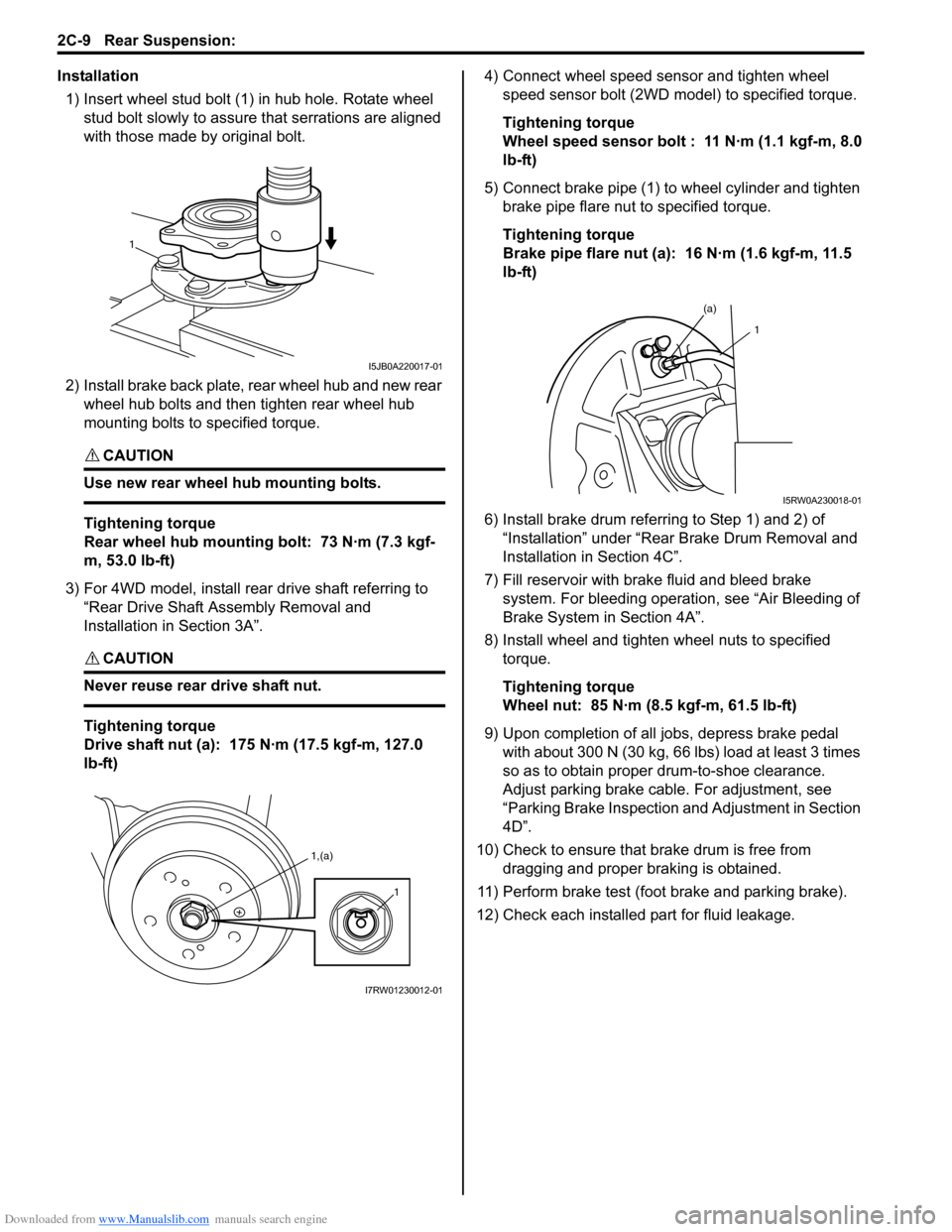
1) Insert wheel stud bolt (1) in hub hole. Rotate wheel
stud bolt slowly to assure that serrations are aligned
with those made by original bolt.
2) Install brake back plate, rear wheel hub and new rear
wheel hub bolts and then tighten rear wheel hub
mounting bolts to specified torque.
CAUTION!
Use new rear wheel hub mounting bolts.
Tightening torque
Rear wheel hub mounting bolt: 73 N·m (7.3 kgf-
m, 53.0 lb-ft)
3) For 4WD model, install rear drive shaft referring to
“Rear Drive Shaft Assembly Removal and
Installation in Section 3A”.
CAUTION!
Never reuse rear drive shaft nut.
Tightening torque
Drive shaft nut (a): 175 N·m (17.5 kgf-m, 127.0
lb-ft)4) Connect wheel speed sensor and tighten wheel
speed sensor bolt (2WD model) to specified torque.
Tightening torque
Wheel speed sensor bolt : 11 N·m (1.1 kgf-m, 8.0
lb-ft)
5) Connect brake pipe (1) to wheel cylinder and tighten
brake pipe flare nut to specified torque.
Tightening torque
Brake pipe flare nut (a): 16 N·m (1.6 kgf-m, 11.5
lb-ft)
6) Install brake drum referring to Step 1) and 2) of
“Installation” under “Rear Brake Drum Removal and
Installation in Section 4C”.
7) Fill reservoir with brake fluid and bleed brake
system. For bleeding operation, see “Air Bleeding of
Brake System in Section 4A”.
8) Install wheel and tighten wheel nuts to specified
torque.
Tightening torque
Wheel nut: 85 N·m (8.5 kgf-m, 61.5 lb-ft)
9) Upon completion of all jobs, depress brake pedal
with about 300 N (30 kg, 66 lbs) load at least 3 times
so as to obtain proper drum-to-shoe clearance.
Adjust parking brake cable. For adjustment, see
“Parking Brake Inspection and Adjustment in Section
4D”.
10) Check to ensure that brake drum is free from
dragging and proper braking is obtained.
11) Perform brake test (foot brake and parking brake).
12) Check each installed part for fluid leakage.
1
I5JB0A220017-01
1,(a)
1
I7RW01230012-01
(a)
1
I5RW0A230018-01
Page 469 of 1556
Downloaded from www.Manualslib.com manuals search engine Rear Suspension: 2C-10
Specifications
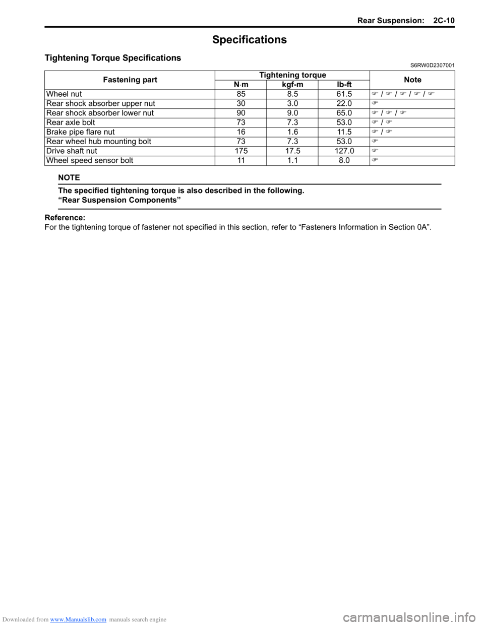
Tightening Torque SpecificationsS6RW0D2307001
NOTE
The specified tightening torque is also described in the following.
“Rear Suspension Components”
Reference:
For the tightening torque of fastener not specified in this section, refer to “Fasteners Information in Section 0A”. Fastening partTightening torque
Note
N⋅mkgf-mlb-ft
Wheel nut 85 8.5 61.5�) / �) / �) / �) / �)
Rear shock absorber upper nut 30 3.0 22.0�)
Rear shock absorber lower nut 90 9.0 65.0�) / �) / �)
Rear axle bolt 73 7.3 53.0�) / �)
Brake pipe flare nut 16 1.6 11.5�) / �)
Rear wheel hub mounting bolt 73 7.3 53.0�)
Drive shaft nut 175 17.5 127.0�)
Wheel speed sensor bolt 11 1.1 8.0�)
Page 482 of 1556
Downloaded from www.Manualslib.com manuals search engine 3A-3 Drive Shaft / Axle: Front
Front Drive Shaft Assembly On-Vehicle
Inspection
S6RW0D3116002
• Check boots for breakage or deterioration.
• Check wheel side joint for rattle or smooth rotation.
• Check differential side (or center shaft side) joint for
smooth rotation.
If any abnormality is found, replace.
Front Drive Shaft Assembly Removal and
Installation
S6RW0D3116003
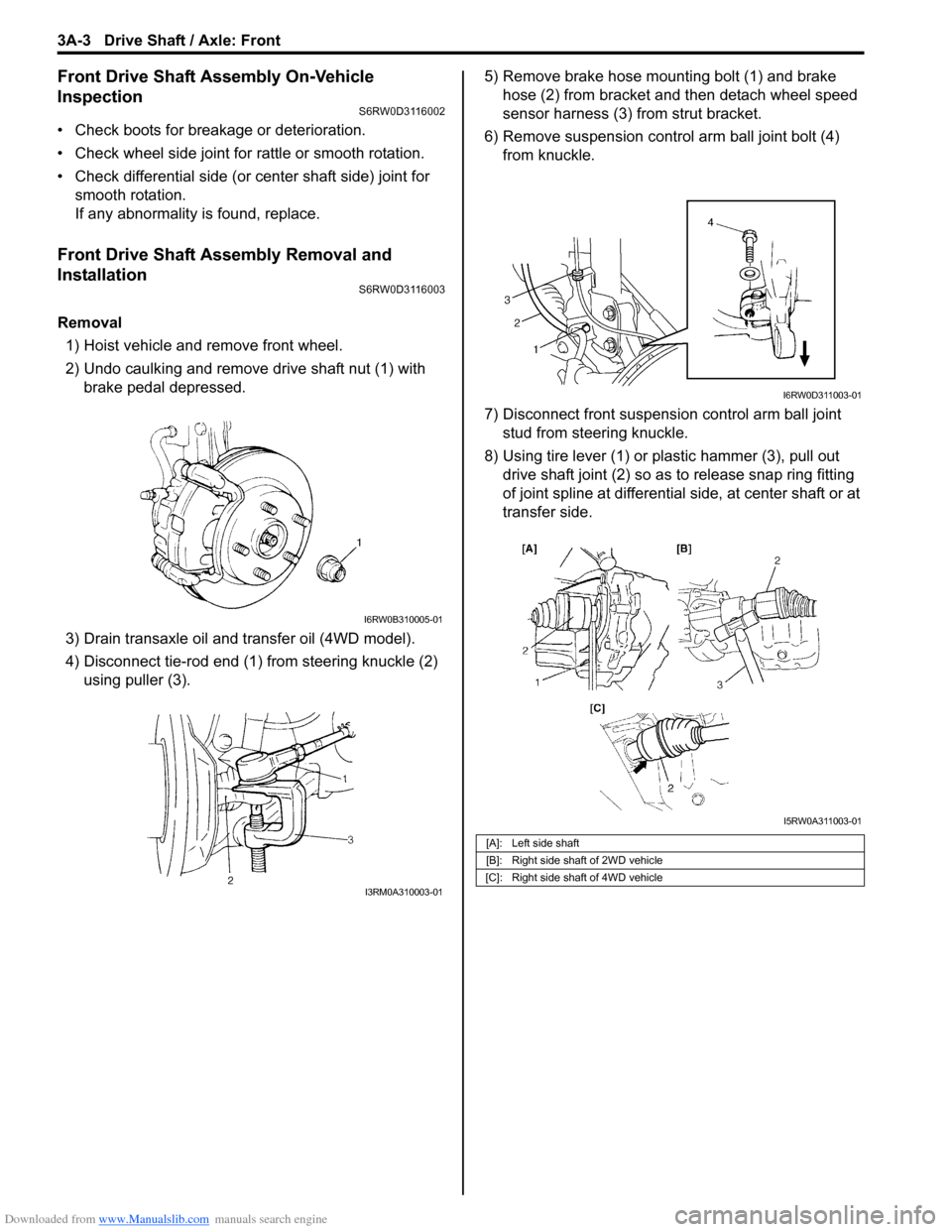
Removal
1) Hoist vehicle and remove front wheel.
2) Undo caulking and remove drive shaft nut (1) with
brake pedal depressed.
3) Drain transaxle oil and transfer oil (4WD model).
4) Disconnect tie-rod end (1) from steering knuckle (2)
using puller (3).5) Remove brake hose mounting bolt (1) and brake
hose (2) from bracket and then detach wheel speed
sensor harness (3) from strut bracket.
6) Remove suspension control arm ball joint bolt (4)
from knuckle.
7) Disconnect front suspension control arm ball joint
stud from steering knuckle.
8) Using tire lever (1) or plastic hammer (3), pull out
drive shaft joint (2) so as to release snap ring fitting
of joint spline at differential side, at center shaft or at
transfer side.
I6RW0B310005-01
I3RM0A310003-01
[A]: Left side shaft
[B]: Right side shaft of 2WD vehicle
[C]: Right side shaft of 4WD vehicle
I6RW0D311003-01
I5RW0A311003-01
Page 570 of 1556
Downloaded from www.Manualslib.com manuals search engine 4-ii Table of Contents
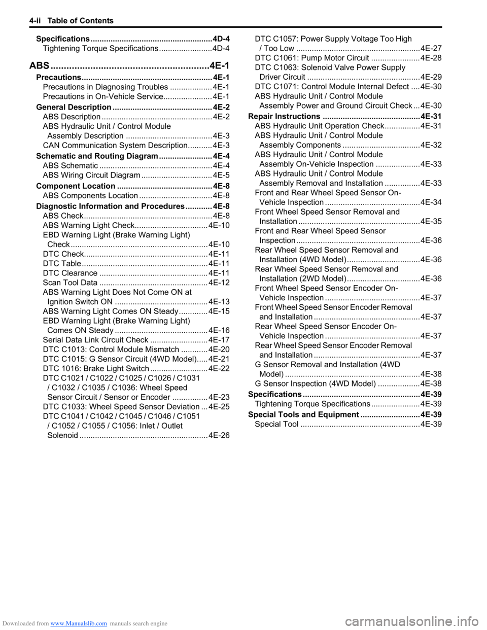
Specifications .......................................................4D-4
Tightening Torque Specifications ........................4D-4
ABS ............................................................4E-1
Precautions........................................................... 4E-1
Precautions in Diagnosing Troubles ................... 4E-1
Precautions in On-Vehicle Service...................... 4E-1
General Description ............................................. 4E-2
ABS Description .................................................. 4E-2
ABS Hydraulic Unit / Control Module
Assembly Description ....................................... 4E-3
CAN Communication System Description........... 4E-3
Schematic and Routing Diagram ........................ 4E-4
ABS Schematic ................................................... 4E-4
ABS Wiring Circuit Diagram ................................ 4E-5
Component Location ........................................... 4E-8
ABS Components Location ................................. 4E-8
Diagnostic Information and Procedures ............ 4E-8
ABS Check .......................................................... 4E-8
ABS Warning Light Check................................. 4E-10
EBD Warning Light (Brake Warning Light)
Check .............................................................. 4E-10
DTC Check........................................................ 4E-11
DTC Table ......................................................... 4E-11
DTC Clearance ................................................. 4E-11
Scan Tool Data ................................................. 4E-12
ABS Warning Light Does Not Come ON at
Ignition Switch ON .......................................... 4E-13
ABS Warning Light Comes ON Steady ............. 4E-15
EBD Warning Light (Brake Warning Light)
Comes ON Steady .......................................... 4E-16
Serial Data Link Circuit Check .......................... 4E-17
DTC C1013: Control Module Mismatch ............ 4E-20
DTC C1015: G Sensor Circuit (4WD Model)..... 4E-21
DTC 1016: Brake Light Switch .......................... 4E-22
DTC C1021 / C1022 / C1025 / C1026 / C1031
/ C1032 / C1035 / C1036: Wheel Speed
Sensor Circuit / Sensor or Encoder ................ 4E-23
DTC C1033: Wheel Speed Sensor Deviation ... 4E-25
DTC C1041 / C1042 / C1045 / C1046 / C1051
/ C1052 / C1055 / C1056: Inlet / Outlet
Solenoid .......................................................... 4E-26DTC C1057: Power Supply Voltage Too High
/ Too Low ........................................................ 4E-27
DTC C1061: Pump Motor Circuit ...................... 4E-28
DTC C1063: Solenoid Valve Power Supply
Driver Circuit ................................................... 4E-29
DTC C1071: Control Module Internal Defect .... 4E-30
ABS Hydraulic Unit / Control Module
Assembly Power and Ground Circuit Check ... 4E-30
Repair Instructions ............................................ 4E-31
ABS Hydraulic Unit Operation Check................ 4E-31
ABS Hydraulic Unit / Control Module
Assembly Components ................................... 4E-32
ABS Hydraulic Unit / Control Module
Assembly On-Vehicle Inspection .................... 4E-33
ABS Hydraulic Unit / Control Module
Assembly Removal and Installation ................ 4E-33
Front and Rear Wheel Speed Sensor On-
Vehicle Inspection ........................................... 4E-34
Front Wheel Speed Sensor Removal and
Installation ....................................................... 4E-35
Front and Rear Wheel Speed Sensor
Inspection ........................................................ 4E-36
Rear Wheel Speed Sensor Removal and
Installation (4WD Model) ................................. 4E-36
Rear Wheel Speed Sensor Removal and
Installation (2WD Model) ................................. 4E-36
Front Wheel Speed Sensor Encoder On-
Vehicle Inspection ........................................... 4E-37
Front Wheel Speed Sensor Encoder Removal
and Installation ................................................ 4E-37
Rear Wheel Speed Sensor Encoder On-
Vehicle Inspection ........................................... 4E-37
Rear Wheel Speed Sensor Encoder Removal
and Installation ................................................ 4E-37
G Sensor Removal and Installation (4WD
Model) ............................................................. 4E-38
G Sensor Inspection (4WD Model) ................... 4E-38
Specifications ..................................................... 4E-39
Tightening Torque Specifications ...................... 4E-39
Special Tools and Equipment ........................... 4E-39
Special Tool ...................................................... 4E-39
Page 606 of 1556
Downloaded from www.Manualslib.com manuals search engine 4E-1 ABS:
Brakes
ABS
Precautions
Precautions in Diagnosing TroublesS6RW0D4500001
To ensure that the trouble diagnosis is done accurately
and smoothly, observe the following and follow “ABS
Check”.
• Diagnostic information stored in ABS control module
memory can be cleared as well as checked by using
SUZUKI scan tool. Before using scan tool, read its
Operator's (Instruction) Manual carefully to have good
understanding as to what functions are available and
how to use it.
• If the vehicle was operated in any of the following
ways, ABS warning light may light momentarily but
this does not indicate anything abnormal in ABS.
– The vehicle was driven with parking brake pulled.
– The vehicle was driven with brake dragging.
– The vehicle was stuck in mud, sand, etc.
– Wheel spin occurred while driving.
– Wheel(s) was rotated while the vehicle was jacked
up.
• Be sure to read “Precautions for Electrical Circuit
Service in Section 00” and “Precaution for CAN
Communication System in Section 00” before
inspection and observe what is written there.
• Be sure to use the trouble diagnosis procedure as
described in “ABS Check”. Failure to follow it may
result in incorrect diagnosis. (Some other diagnosis
trouble code may be stored by mistake in the memory
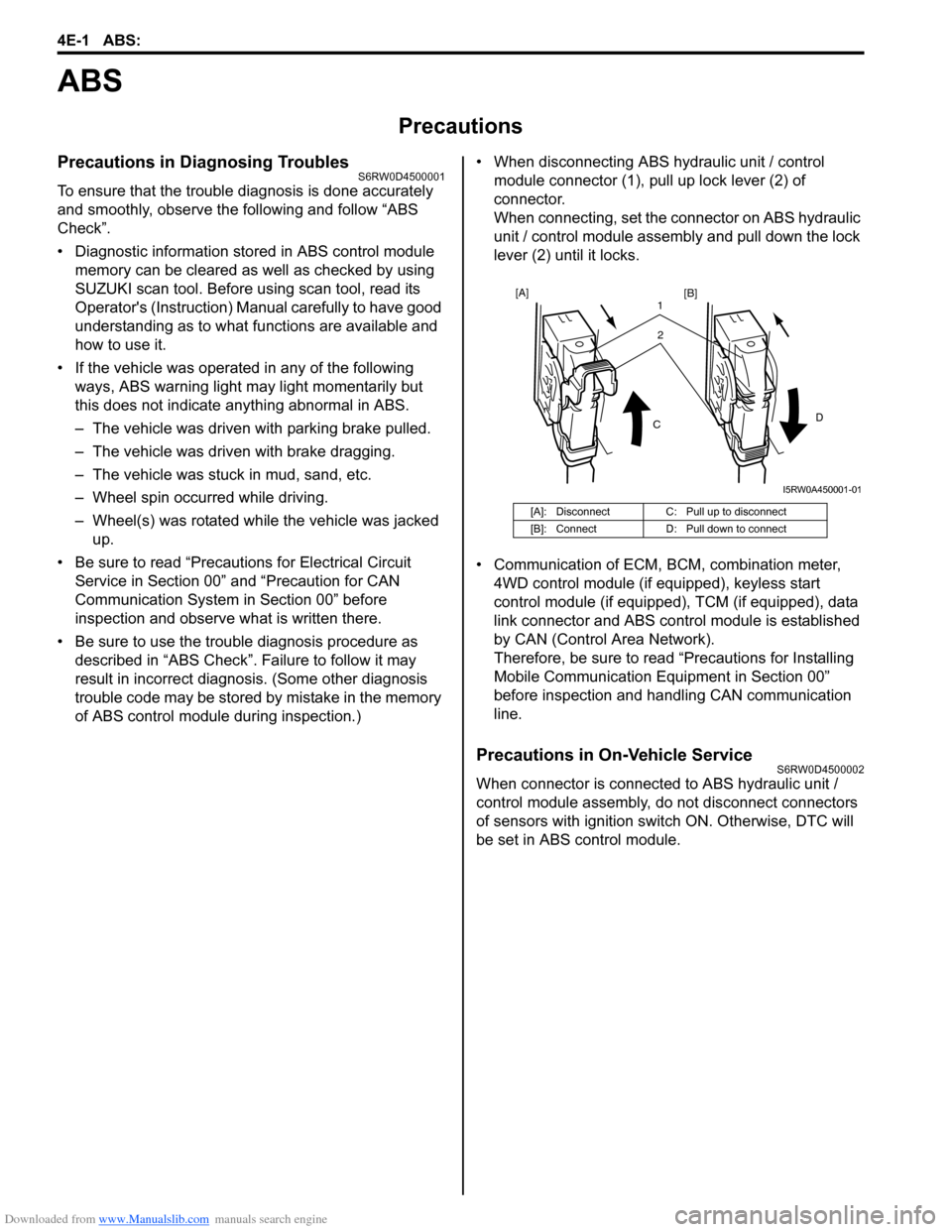
of ABS control module during inspection.)• When disconnecting ABS hydraulic unit / control
module connector (1), pull up lock lever (2) of
connector.
When connecting, set the connector on ABS hydraulic
unit / control module assembly and pull down the lock
lever (2) until it locks.
• Communication of ECM, BCM, combination meter,
4WD control module (if equipped), keyless start
control module (if equipped), TCM (if equipped), data
link connector and ABS control module is established
by CAN (Control Area Network).
Therefore, be sure to read “Precautions for Installing
Mobile Communication Equipment in Section 00”
before inspection and handling CAN communication
line.
Precautions in On-Vehicle ServiceS6RW0D4500002
When connector is connected to ABS hydraulic unit /
control module assembly, do not disconnect connectors
of sensors with ignition switch ON. Otherwise, DTC will
be set in ABS control module.
[A]: Disconnect C: Pull up to disconnect
[B]: Connect D: Pull down to connect
2 1
CD
[A]
[B]
I5RW0A450001-01
Page 607 of 1556
Downloaded from www.Manualslib.com manuals search engine ABS: 4E-2
General Description
ABS DescriptionS6RW0D4501001
The ABS (Antilock Brake System) controls the fluid
pressure applied to the wheel cylinder of each brake
from the master cylinder so that each wheel is not locked
even when hard braking is applied.
This ABS has also the following function.
While braking is applied, but before ABS control
becomes effective, braking force is distributed between
the front and rear so as to prevent the rear wheels from
being locked too early for better stability of the vehicle.
The main component parts of this ABS include the
following parts in addition to those of the conventional
brake system.
• Wheel speed sensor which senses revolution speed
of each wheel and outputs its signal.
Rear wheel speed sensor of 4WD vehicle is
integrated in rear wheel hub assembly and supplied
as rear wheel hub assembly part.
Front wheel speed sensor and rear wheel speed
sensor of 2WD model are separated from wheel hub
assembly and supplied as spare parts.
• ABS warning light which lights to inform abnormality
when system fails to operate properly.• ABS hydraulic unit / control module assembly is
incorporated ABS control module, ABS hydraulic unit
(actuator assembly), solenoid valve power supply
driver (transistor), solenoid valve driver (transistor),
pump motor driver (transistor).
– ABS control module which sends operation signal
to ABS hydraulic unit to control fluid pressure
applied to each wheel cylinder based on signal
from each wheel speed sensor so as to prevent
wheel from locking.
– ABS hydraulic unit which operates according to
signal from ABS control module to control fluid
pressure applied to wheel cylinder of each 4
wheels.
– Solenoid valve power supply driver (transistor)
which supplies power to solenoid valve in ABS
hydraulic unit.
– Solenoid valve driver (transistor) which controls
each solenoid valves in ABS hydraulic unit.
– Pump motor driver (transistor) which supplies
power to pump motor in ABS hydraulic unit.
• G sensor which detects body deceleration speed for
4WD model.
This ABS is equipped with Electronic Brake force
Distribution (EBD) system that controls a fluid pressure
of rear wheels to best condition, which is the same
function as that of proportioning valve, by the signal from
wheel sensor independently of change of load due to
load capacity and so on. And if the EBD system fails to
operate properly, the brake warning light lights to inform
abnormality.
Page 609 of 1556
Downloaded from www.Manualslib.com manuals search engine ABS: 4E-4
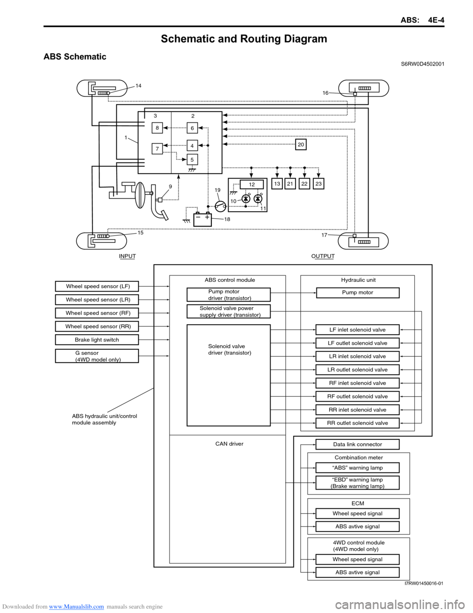
Schematic and Routing Diagram
ABS SchematicS6RW0D4502001
13
2
8
6
5 7
12
4
15
17
1614
9
18
19
11 10
20
21221323
INPUTOUTPUT
ABS control module
Wheel speed sensor (LR)
Wheel speed sensor (RF)
G sensor
(4WD model only)Wheel speed sensor (LF)Pump motor
driver (transistor)
Solenoid valve power
supply driver (transistor)Hydraulic unit
Pump motor
LF inlet solenoid valve
LF outlet solenoid valve
LR inlet solenoid valve
LR outlet solenoid valve
RF inlet solenoid valve
RF outlet solenoid valve
RR inlet solenoid valve
RR outlet solenoid valve
“ABS” warning lamp
“EBD” warning lamp
(Brake warning lamp)Data link connector
ABS hydraulic unit/control
module assembly
Wheel speed sensor (RR)
Brake light switch
CAN driver
Combination meter
Wheel speed signal
ECM
Wheel speed signal
ABS avtive signal
ABS avtive signal
4WD control module
(4WD model only)
Solenoid valve
driver (transistor)
I7RW01450016-01