brake sensor SUZUKI SX4 2006 1.G Service Repair Manual
[x] Cancel search | Manufacturer: SUZUKI, Model Year: 2006, Model line: SX4, Model: SUZUKI SX4 2006 1.GPages: 1556, PDF Size: 37.31 MB
Page 686 of 1556
Downloaded from www.Manualslib.com manuals search engine 5A-38 Automatic Transmission/Transaxle:
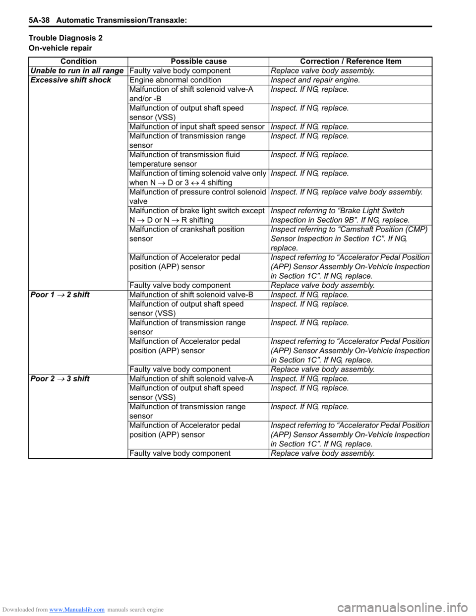
Trouble Diagnosis 2
On-vehicle repair
Condition Possible cause Correction / Reference Item
Unable to run in all rangeFaulty valve body componentReplace valve body assembly.
Excessive shift shockEngine abnormal conditionInspect and repair engine.
Malfunction of shift solenoid valve-A
and/or -BInspect. If NG, replace.
Malfunction of output shaft speed
sensor (VSS)Inspect. If NG, replace.
Malfunction of input shaft speed sensorInspect. If NG, replace.
Malfunction of transmission range
sensorInspect. If NG, replace.
Malfunction of transmission fluid
temperature sensorInspect. If NG, replace.
Malfunction of timing solenoid valve only
when N → D or 3 ↔ 4 shiftingInspect. If NG, replace.
Malfunction of pressure control solenoid
valveInspect. If NG, replace valve body assembly.
Malfunction of brake light switch except
N → D or N → R shiftingInspect referring to “Brake Light Switch
Inspection in Section 9B”. If NG, replace.
Malfunction of crankshaft position
sensorInspect referring to “Camshaft Position (CMP)
Sensor Inspection in Section 1C”. If NG,
replace.
Malfunction of Accelerator pedal
position (APP) sensorInspect referring to “Accelerator Pedal Position
(APP) Sensor Assembly On-Vehicle Inspection
in Section 1C”. If NG, replace.
Faulty valve body componentReplace valve body assembly.
Poor 1
→ 2 shiftMalfunction of shift solenoid valve-BInspect. If NG, replace.
Malfunction of output shaft speed
sensor (VSS)Inspect. If NG, replace.
Malfunction of transmission range
sensorInspect. If NG, replace.
Malfunction of Accelerator pedal
position (APP) sensorInspect referring to “Accelerator Pedal Position
(APP) Sensor Assembly On-Vehicle Inspection
in Section 1C”. If NG, replace.
Faulty valve body componentReplace valve body assembly.
Poor 2
→ 3 shiftMalfunction of shift solenoid valve-AInspect. If NG, replace.
Malfunction of output shaft speed
sensor (VSS)Inspect. If NG, replace.
Malfunction of transmission range
sensorInspect. If NG, replace.
Malfunction of Accelerator pedal
position (APP) sensorInspect referring to “Accelerator Pedal Position
(APP) Sensor Assembly On-Vehicle Inspection
in Section 1C”. If NG, replace.
Faulty valve body componentReplace valve body assembly.
Page 688 of 1556
Downloaded from www.Manualslib.com manuals search engine 5A-40 Automatic Transmission/Transaxle:
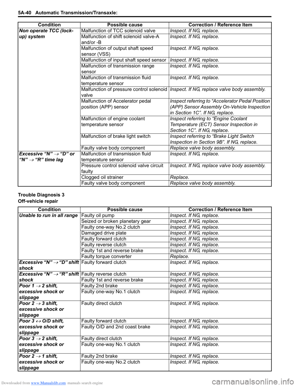
Trouble Diagnosis 3
Off-vehicle repairNon operate TCC (lock-
up) systemMalfunction of TCC solenoid valveInspect. If NG, replace.
Malfunction of shift solenoid valve-A
and/or -BInspect. If NG, replace.
Malfunction of output shaft speed
sensor (VSS)Inspect. If NG, replace.
Malfunction of input shaft speed sensorInspect. If NG, replace.
Malfunction of transmission range
sensorInspect. If NG, replace.
Malfunction of transmission fluid
temperature sensorInspect. If NG, replace.
Malfunction of pressure control solenoid
valveInspect. If NG, replace valve body assembly.
Malfunction of Accelerator pedal
position (APP) sensorInspect referring to “Accelerator Pedal Position
(APP) Sensor Assembly On-Vehicle Inspection
in Section 1C”. If NG, replace.
Malfunction of engine coolant
temperature sensorInspect referring to “Engine Coolant
Temperature (ECT) Sensor Inspection in
Section 1C”. If NG, replace.
Malfunction of brake light switchInspect referring to “Brake Light Switch
Inspection in Section 9B”. If NG, replace.
Faulty valve body componentReplace valve body assembly.
Excessive “N”
→ “D” or
“N”
→ “R” time lagMalfunction of transmission fluid
temperature sensorInspect. If NG, replace.
Pressure control solenoid valve circuit
faultyInspect. If NG, replace valve body assembly.
Clogged oil strainerReplace.
Faulty valve body componentReplace valve body assembly. Condition Possible cause Correction / Reference Item
Condition Possible cause Correction / Reference Item
Unable to run in all rangeFaulty oil pumpInspect. If NG, replace.
Seized or broken planetary gearInspect. If NG, replace.
Faulty one-way No.2 clutchInspect. If NG, replace.
Damaged drive plateInspect. If NG, replace.
Faulty forward clutchInspect. If NG, replace.
Faulty reverse clutchInspect. If NG, replace.
Faulty 1st and reverse brakeInspect. If NG, replace.
Faulty torque converterReplace.
Excessive “N”
→ “D” shift
shockFaulty forward clutchInspect. If NG, replace.
Excessive “N”
→ “R” shift
shockFaulty reverse clutchInspect. If NG, replace.
Faulty 1st and reverse brakeInspect. If NG, replace.
Poor 1
→ 2 shift,
excessive shock or
slippageFaulty 2nd brakeInspect. If NG, replace.
Faulty one-way No.1 clutchInspect. If NG, replace.
Poor 2
→ 3 shift,
excessive shock or
slippageFaulty direct clutchInspect. If NG, replace.
Poor 3
↔ O/D shift,
excessive shock or
slippageFaulty forward clutchInspect. If NG, replace.
Faulty O/D and 2nd coast brakeInspect. If NG, replace.
Poor 3
→ 2 shift,
excessive shock or
slippageFaulty direct clutchInspect. If NG, replace.
Faulty one-way No.1 clutchInspect. If NG, replace.
Poor 2
→ 1 shift,
excessive shock or
slippageFaulty 2nd brakeInspect. If NG, replace.
Faulty one-way No.2 clutchInspect. If NG, replace.
Page 751 of 1556
Downloaded from www.Manualslib.com manuals search engine Automatic Transmission/Transaxle: 5A-103
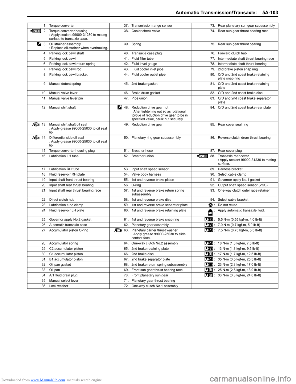
1. Torque converter 37. Transmission range sensor 73. Rear planetary sun gear subassembly
2. Torque converter housing
: Apply sealant 99000-31230 to mating
surface to transaxle case.38. Cooler check valve 74. Rear sun gear thrust bearing race
3. Oil strainer assembly
: Replace oil strainer when overhauling.39. Spring 75. Rear sun gear thrust bearing
4. Parking lock pawl shaft 40. Transaxle case plug 76. Forward clutch hub
5. Parking lock pawl 41. Fluid filler tube 77. Intermediate shaft thrust bearing race
6. Parking lock pawl return spring 42. Fluid level gauge 78. Intermediate shaft thrust bearing
7. Parking lock pawl rod 43. Fluid cooler inlet pipe 79. 2nd brake piston snap ring
8. Parking lock pawl bracket 44. Fluid cooler outlet pipe 80. O/D and 2nd coast brake retaining
plate snap ring
9. Manual detent spring 45. 2nd brake gasket 81. O/D and 2nd coast brake retaining
plate
10. Manual valve lever 46. Brake drum gasket 82. O/D and 2nd coast brake disc
11. Manual valve lever pin 47. Pipe union 83. O/D and 2nd coast brake separator
plate
12. Manual shift shaft 48. Reduction drive gear nut
: After tightening nut so as rotational
torque of reduction drive gear to be in
specified value, caulk nut securely.84. O/D and 2nd coast brake rear plate
13. Manual shift shaft oil seal
: Apply grease 99000-25030 to oil seal
lip.49. Reduction drive gear 85. Rear cover seal ring
14. Differential side oil seal
: Apply grease 99000-25030 to oil seal
lip.50. Planetary ring gear subassembly 86. Reverse clutch drum thrust bearing
15. Torque converter housing plug 51. Breather hose 87. Rear cover plug
16. Lubrication LH tube 52. Breather union 88. Transaxle rear cover
: Apply sealant 99000-31230 to mating
surface.
17. Lubrication RH tube 53. Input shaft speed sensor 89. Harness bracket
18. Fluid reservoir RH plate 54. Valve body harness 90. Select cable clamp
19. Input shaft front thrust bearing 55. 1st and reverse brake piston 91. Governor apply No.1 gasket
20. Input shaft rear thrust bearing 56. O-ring 92. Output shaft speed sensor (VSS)
21. Input shaft rear thrust bearing race 57. 1st and reverse brake return spring
subassembly93. One-way clutch outer race retainer
22. Direct clutch hub 58. 1st and reverse brake disc 94. Select cable bracket
23. Lubrication tube clamp 59. 1st and reverse brake separator plate : Do not reuse.
24. Fluid reservoir LH plate 60. 1st and reverse brake retaining plate : Apply automatic transaxle fluid.
25. Governor apply No.2 gasket 61. 1st and reverse brake snap ring : 5.5 N⋅m (0.55 kgf-m, 4.0 lb-ft)
26. Automatic transaxle case 62. Planetary gear assembly : 7.0 N⋅m (0.7 kgf-m, 5.0 lb-ft)
27. Accumulator piston O-ring 63. Planetary carrier thrust washer
: Apply grease 99000-25030 to slide
contact face.: 7.5 N⋅m (0.75 kgf-m, 5.5 lb-ft)
28. Accumulator spring 64. One-way clutch No.2 assembly : 10 N⋅m (1.0 kgf-m, 7.5 lb-ft)
29. C2 accumulator piston 65. 2nd brake retaining plate : 13 N⋅m (1.3 kgf-m, 9.5 lb-ft)
30. C1 accumulator piston 66. 2nd brake disc : 17 N⋅m (1.7 kgf-m, 12.5 lb-ft)
31. B1 accumulator piston 67. 2nd brake separator plate : 35 N⋅m (3.5 kgf-m, 25.5 lb-ft)
32. Oil pan gasket 68. 2nd brake return spring subassembly : 23 N⋅m (2.3 kgf-m, 17.0 lb-ft)
33. Oil pan 69. Front sun gear thrust bearing race : 25 N⋅m (2.5 kgf-m, 18.0 lb-ft)
34. A/T fluid drain plug 70. Front planetary sun gear : 33 N⋅m (3.3 kgf-m, 24.0 lb-ft)
35. Manual select lever 71. Planetary gear thrust bearing
36. Lock washer 72. One-way clutch No.1 assembly
Page 809 of 1556
Downloaded from www.Manualslib.com manuals search engine Automatic Transmission/Transaxle: 5A-161
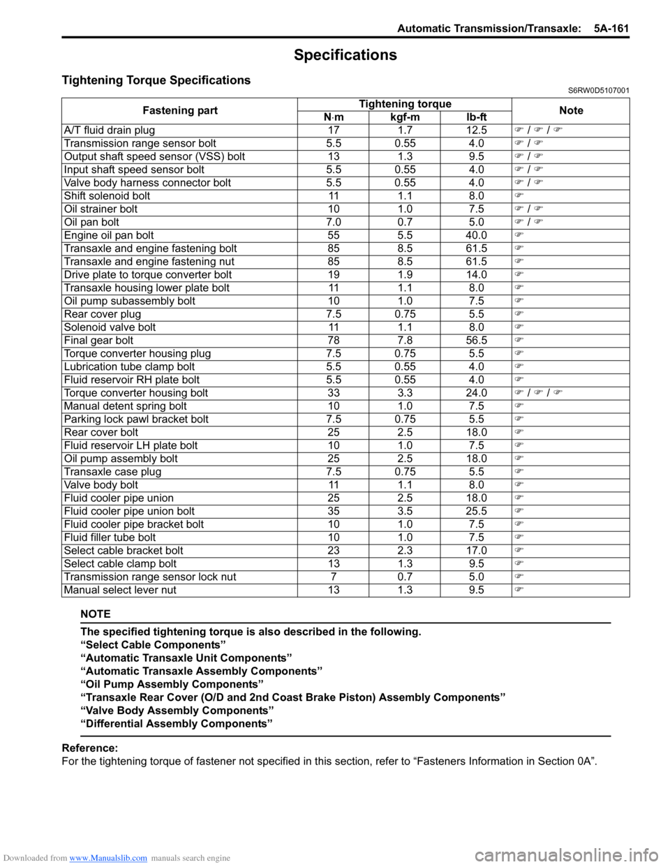
Specifications
Tightening Torque SpecificationsS6RW0D5107001
NOTE
The specified tightening torque is also described in the following.
“Select Cable Components”
“Automatic Transaxle Unit Components”
“Automatic Transaxle Assembly Components”
“Oil Pump Assembly Components”
“Transaxle Rear Cover (O/D and 2nd Coast Brake Piston) Assembly Components”
“Valve Body Assembly Components”
“Differential Assembly Components”
Reference:
For the tightening torque of fastener not specified in this section, refer to “Fasteners Information in Section 0A”. Fastening partTightening torque
Note
N⋅mkgf-mlb-ft
A/T fluid drain plug 17 1.7 12.5�) / �) / �)
Transmission range sensor bolt 5.5 0.55 4.0�) / �)
Output shaft speed sensor (VSS) bolt 13 1.3 9.5�) / �)
Input shaft speed sensor bolt 5.5 0.55 4.0�) / �)
Valve body harness connector bolt 5.5 0.55 4.0�) / �)
Shift solenoid bolt 11 1.1 8.0�)
Oil strainer bolt 10 1.0 7.5�) / �)
Oil pan bolt 7.0 0.7 5.0�) / �)
Engine oil pan bolt 55 5.5 40.0�)
Transaxle and engine fastening bolt 85 8.5 61.5�)
Transaxle and engine fastening nut 85 8.5 61.5�)
Drive plate to torque converter bolt 19 1.9 14.0�)
Transaxle housing lower plate bolt 11 1.1 8.0�)
Oil pump subassembly bolt 10 1.0 7.5�)
Rear cover plug 7.5 0.75 5.5�)
Solenoid valve bolt 11 1.1 8.0�)
Final gear bolt 78 7.8 56.5�)
Torque converter housing plug 7.5 0.75 5.5�)
Lubrication tube clamp bolt 5.5 0.55 4.0�)
Fluid reservoir RH plate bolt 5.5 0.55 4.0�)
Torque converter housing bolt 33 3.3 24.0�) / �) / �)
Manual detent spring bolt 10 1.0 7.5�)
Parking lock pawl bracket bolt 7.5 0.75 5.5�)
Rear cover bolt 25 2.5 18.0�)
Fluid reservoir LH plate bolt 10 1.0 7.5�)
Oil pump assembly bolt 25 2.5 18.0�)
Transaxle case plug 7.5 0.75 5.5�)
Valve body bolt 11 1.1 8.0�)
Fluid cooler pipe union 25 2.5 18.0�)
Fluid cooler pipe union bolt 35 3.5 25.5�)
Fluid cooler pipe bracket bolt 10 1.0 7.5�)
Fluid filler tube bolt 10 1.0 7.5�)
Select cable bracket bolt 23 2.3 17.0�)
Select cable clamp bolt 13 1.3 9.5�)
Transmission range sensor lock nut 7 0.7 5.0�)
Manual select lever nut 13 1.3 9.5�)
Page 918 of 1556
Downloaded from www.Manualslib.com manuals search engine 6C-38 Power Assisted Steering System:
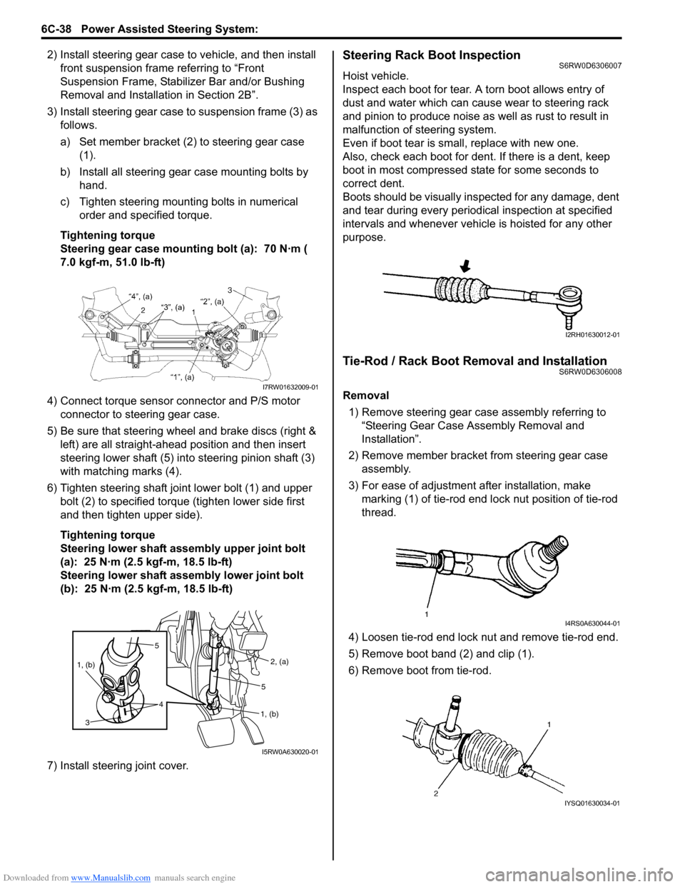
2) Install steering gear case to vehicle, and then install
front suspension frame referring to “Front
Suspension Frame, Stabilizer Bar and/or Bushing
Removal and Installation in Section 2B”.
3) Install steering gear case to suspension frame (3) as
follows.
a) Set member bracket (2) to steering gear case
(1).
b) Install all steering gear case mounting bolts by
hand.
c) Tighten steering mounting bolts in numerical
order and specified torque.
Tightening torque
Steering gear case mounting bolt (a): 70 N·m (
7.0 kgf-m, 51.0 lb-ft)
4) Connect torque sensor connector and P/S motor
connector to steering gear case.
5) Be sure that steering wheel and brake discs (right &
left) are all straight-ahead position and then insert
steering lower shaft (5) into steering pinion shaft (3)
with matching marks (4).
6) Tighten steering shaft joint lower bolt (1) and upper
bolt (2) to specified torque (tighten lower side first
and then tighten upper side).
Tightening torque
Steering lower shaft assembly upper joint bolt
(a): 25 N·m (2.5 kgf-m, 18.5 lb-ft)
Steering lower shaft assembly lower joint bolt
(b): 25 N·m (2.5 kgf-m, 18.5 lb-ft)
7) Install steering joint cover.Steering Rack Boot InspectionS6RW0D6306007
Hoist vehicle.
Inspect each boot for tear. A torn boot allows entry of
dust and water which can cause wear to steering rack
and pinion to produce noise as well as rust to result in
malfunction of steering system.
Even if boot tear is small, replace with new one.
Also, check each boot for dent. If there is a dent, keep
boot in most compressed state for some seconds to
correct dent.
Boots should be visually inspected for any damage, dent
and tear during every periodical inspection at specified
intervals and whenever vehicle is hoisted for any other
purpose.
Tie-Rod / Rack Boot Removal and InstallationS6RW0D6306008
Removal
1) Remove steering gear case assembly referring to
“Steering Gear Case Assembly Removal and
Installation”.
2) Remove member bracket from steering gear case
assembly.
3) For ease of adjustment after installation, make
marking (1) of tie-rod end lock nut position of tie-rod
thread.
4) Loosen tie-rod end lock nut and remove tie-rod end.
5) Remove boot band (2) and clip (1).
6) Remove boot from tie-rod.I7RW01632009-01
5
4 1, (b)
3
2, (a)
1, (b)5
I5RW0A630020-01
I2RH01630012-01
I4RS0A630044-01
IYSQ01630034-01
Page 1163 of 1556
Downloaded from www.Manualslib.com manuals search engine Table of Contents 9-iii
Headlight Bulb Replacement (Discharge
Headlight Model) ............................................. 9B-19
Ballast Removal and Installation (Discharge
Headlight Model) ............................................. 9B-19
Igniter Removal and Installation (Discharge
Headlight Model) ............................................. 9B-20
Headlight Aiming Adjustment with Screen ........ 9B-20
Headlight Switch (in Lighting Switch)
Removal and Installation................................. 9B-22
Headlight Switch (in Lighting Switch)
Inspection........................................................ 9B-22
Hazard Warning Switch Removal and
Installation ....................................................... 9B-23
Hazard Warning Switch Inspection ................... 9B-23
Brake Light Switch Inspection ........................... 9B-23
Turn Signal Light Switch (in Lighting Switch)
Removal and Installation................................. 9B-24
Turn Signal Light Switch (in Lighting Switch)
Inspection........................................................ 9B-24
Turn Signal and Hazard Warning Relay
Removal and Installation................................. 9B-24
Turn Signal and Hazard Warning Relay
Inspection........................................................ 9B-25
License Light Assembly Removal and
Installation ....................................................... 9B-25
Front Fog Light Assembly Removal and
Installation (If Equipped) ................................. 9B-26
Front Fog Light Switch Inspection (If
Equipped)........................................................ 9B-26
Front Fog Light Aiming Adjustment with
Screen (If Equipped) ....................................... 9B-26
Rear Fog Light Switch Inspection (If
Equipped)........................................................ 9B-27
Headlight Manual Levering Switch Inspection
(If Equipped) ................................................... 9B-28
Headlight Leveling Actuator Inspection (If
Equipped)........................................................ 9B-28
Height Sensor Removal and Installation (If
Equipped)........................................................ 9B-29
Height Sensor and Its Circuit Inspection (If
Equipped)........................................................ 9B-30
Headlight Leveling Control Module Removal
and Installation (If Equipped) .......................... 9B-30
Initialization of Headlight Auto Leveling
System ............................................................ 9B-30
Auto-On Headlight Sensor Inspection (If
Equipped)........................................................ 9B-31
Illumination Cancel Switch Inspection (If
Equipped)........................................................ 9B-32
Tail Light Relay, Headlight Relay, Front Fog
Light Relay Inspection (If Equipped) ............... 9B-32
Specifications..................................................... 9B-33
Tightening Torque Specifications ...................... 9B-33
Instrumentation / Driver Info. / Horn ...... 9C-1
Precautions........................................................... 9C-1
Precautions in Diagnosing Troubles for
Combination Meter............................................ 9C-1
General Description ............................................. 9C-1
CAN Communication System Description........... 9C-1Auto Volume Control System Description (If
Equipped) ..........................................................9C-3
Schematic and Routing Diagram ........................9C-4
Combination Meter Circuit Diagram ....................9C-4
Component Location ...........................................9C-5
Audio System Component Location ....................9C-5
Diagnostic Information and Procedures ............9C-6
Speedometer and VSS Symptom Diagnosis ......9C-6
Tachometer Symptom Diagnosis ........................9C-6
Engine Coolant Temperature (ECT) Meter
Symptom Diagnosis ..........................................9C-6
Fuel Meter Symptom Diagnosis ..........................9C-6
Low Fuel Warning Light Symptom Diagnosis .....9C-7
Oil Pressure Warning Light Symptom
Diagnosis ..........................................................9C-7
Brake and Parking Brake Warning Light
Symptom Diagnosis ..........................................9C-8
Seat Belt Reminder Light Symptom Diagnosis ....9C-8
A/T Shift Position Indicator Symptom
Diagnosis (A/T Model).......................................9C-8
Charge Warning Light Symptom Diagnosis ........9C-9
Main Beam (High Beam) Indicator Symptom
Diagnosis ..........................................................9C-9
Warning Buzzer Circuit Symptom Diagnosis ......9C-9
Cigarette Lighter Symptom Diagnosis (If
Equipped) ........................................................9C-10
Horn Symptom Diagnosis .................................9C-10
Information Display Symptom Diagnosis (If
Equipped) ........................................................9C-10
Clock System Diagnosis (If Equipped) ..............9C-11
Audio System Symptom Diagnosis (If
Equipped) ........................................................9C-12
Remote Audio Control Switch Symptom
Diagnosis (If Equipped) ...................................9C-13
Navigation Symptom Diagnosis (If Equipped)...9C-13
Repair Instructions ............................................9C-14
Ignition Switch Removal and Installation...........9C-14
Ignition Switch Inspection..................................9C-14
Combination Meter Removal and Installation ...9C-14
Fuel Level Sensor Removal and Installation .....9C-15
Fuel Level Sensor Inspection ............................9C-15
Oil Pressure Switch Removal and Installation ..9C-15
Oil Pressure Switch Inspection .........................9C-15
Engine Coolant Temperature (ECT) Sensor
Inspection ........................................................9C-16
Brake Fluid Level Switch Inspection .................9C-16
Parking Brake Switch Inspection.......................9C-16
Door Switch (Front / Rear Door) Inspection ......9C-16
Rear End Door Switch Inspection .....................9C-16
Outside Air Temperature Sensor Removal
and Installation (If Equipped) ..........................9C-17
Outside Air Temperature Sensor Inspection
(If Equipped)....................................................9C-17
Instrument Panel Removal and Installation.......9C-17
Information Display (Clock) Removal and
Installation .......................................................9C-18
Audio Unit Removal and Installation (If
Equipped) ........................................................9C-19
Page 1184 of 1556
Downloaded from www.Manualslib.com manuals search engine 9A-17 Wiring Systems:
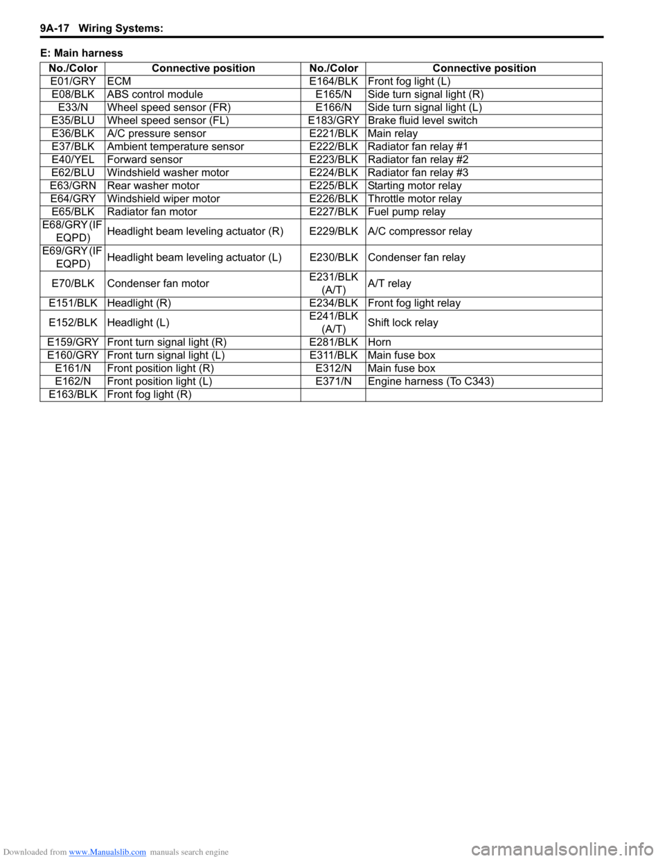
E: Main harness
No./Color Connective position No./Color Connective position
E01/GRY ECM E164/BLK Front fog light (L)
E08/BLK ABS control module E165/N Side turn signal light (R)
E33/N Wheel speed sensor (FR) E166/N Side turn signal light (L)
E35/BLU Wheel speed sensor (FL)E183/GRY Brake fluid level switch
E36/BLK A/C pressure sensor E221/BLK Main relay
E37/BLK Ambient temperature sensor E222/BLK Radiator fan relay #1
E40/YEL Forward sensor E223/BLK Radiator fan relay #2
E62/BLU Windshield washer motor E224/BLK Radiator fan relay #3
E63/GRN Rear washer motor E225/BLK Starting motor relay
E64/GRY Windshield wiper motor E226/BLK Throttle motor relay
E65/BLK Radiator fan motor E227/BLK Fuel pump relay
E68/GRY (IF
EQPD)Headlight beam leveling actuator (R) E229/BLK A/C compressor relay
E69/GRY (IF
EQPD)Headlight beam leveling actuator (L) E230/BLK Condenser fan relay
E70/BLK Condenser fan motorE231/BLK
(A/T)A/T relay
E151/BLK Headlight (R) E234/BLK Front fog light relay
E152/BLK Headlight (L)E241/BLK
(A/T)Shift lock relay
E159/GRY Front turn signal light (R) E281/BLK Horn
E160/GRY Front turn signal light (L) E311/BLK Main fuse box
E161/N Front position light (R) E312/N Main fuse box
E162/N Front position light (L) E371/N Engine harness (To C343)
E163/BLK Front fog light (R)
Page 1185 of 1556
Downloaded from www.Manualslib.com manuals search engine Wiring Systems: 9A-18
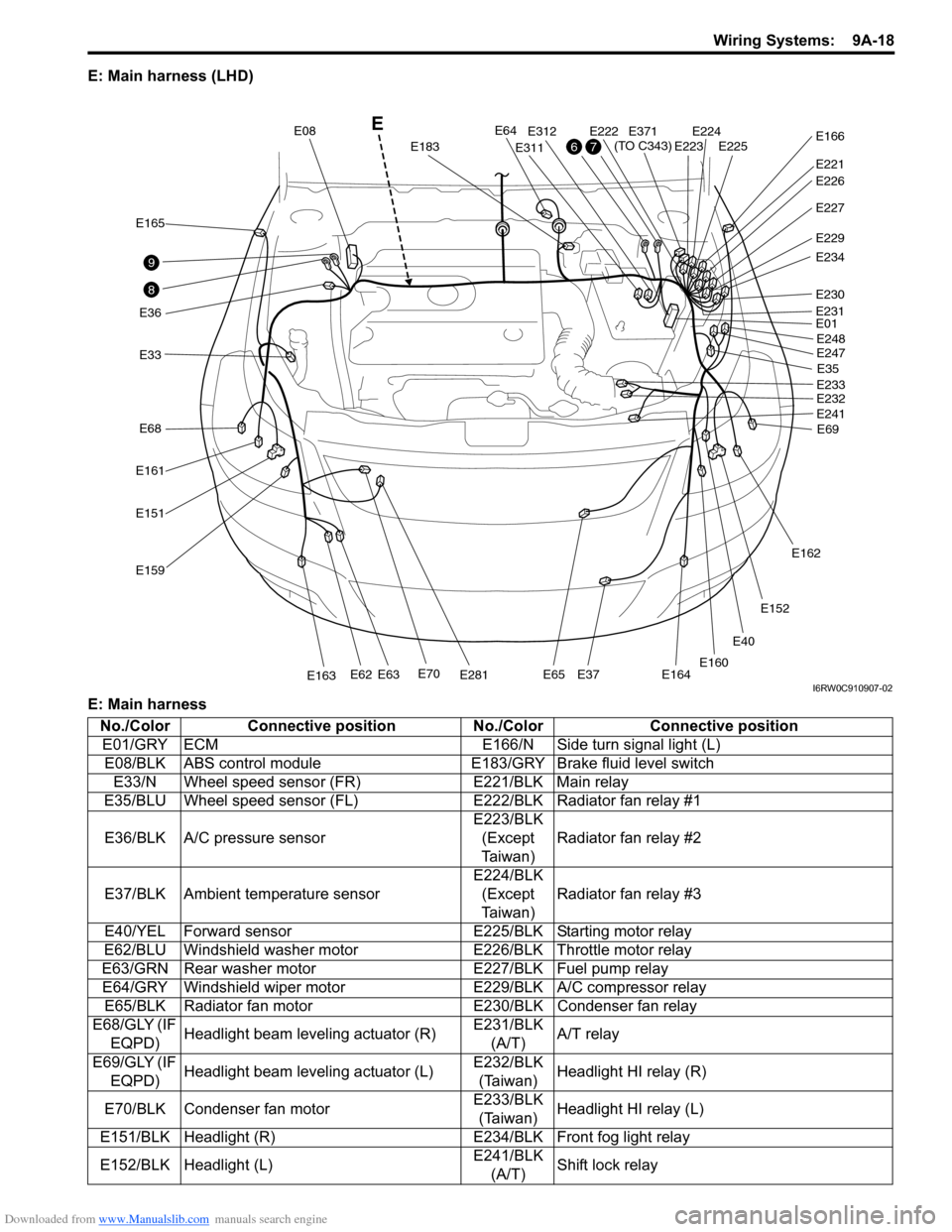
E: Main harness (LHD)
E: Main harness
E40
E33
E165
E36
E161
E68
E151
E159
E70E281E163E62E63E65E37E164
E64
E183
E08
E311
E312E222E224E225E223
E221
E371
(TO C343)E166
E227
E229
E234
E230
E01
E35
E69 E248
E247
E233
E232
E241
E162
E152
E160
E231
E226
8
9
76
E
I6RW0C910907-02
No./Color Connective position No./Color Connective position
E01/GRY ECM E166/N Side turn signal light (L)
E08/BLK ABS control module E183/GRY Brake fluid level switch
E33/N Wheel speed sensor (FR) E221/BLK Main relay
E35/BLU Wheel speed sensor (FL)E222/BLK Radiator fan relay #1
E36/BLK A/C pressure sensorE223/BLK
(Except
Ta i w a n )Radiator fan relay #2
E37/BLK Ambient temperature sensorE224/BLK
(Except
Ta i w a n )Radiator fan relay #3
E40/YEL Forward sensor E225/BLK Starting motor relay
E62/BLU Windshield washer motor E226/BLK Throttle motor relay
E63/GRN Rear washer motor E227/BLK Fuel pump relay
E64/GRY Windshield wiper motor E229/BLK A/C compressor relay
E65/BLK Radiator fan motor E230/BLK Condenser fan relay
E68/GLY (IF
EQPD)Headlight beam leveling actuator (R)E231/BLK
(A/T)A/T relay
E69/GLY (IF
EQPD)Headlight beam leveling actuator (L)E232/BLK
(Taiwan)Headlight HI relay (R)
E70/BLK Condenser fan motorE233/BLK
(Taiwan)Headlight HI relay (L)
E151/BLK Headlight (R) E234/BLK Front fog light relay
E152/BLK Headlight (L)E241/BLK
(A/T)Shift lock relay
Page 1186 of 1556

Downloaded from www.Manualslib.com manuals search engine 9A-19 Wiring Systems:
Instrument PanelS6RW0D910A003
E: Main harness, power steering wire (RHD)
E: Main harness
E: Power steering wireE159/GRY Front turn signal light (R)E247/BLK
(Taiwan)Headlight LO relay (R)
E160/GRY Front turn signal light (L)E248/BLK
(Taiwan)Headlight LO relay (L)
E161/N Front position light (R) E281/BLK Horn
E162/N Front position light (L) E311/BLK Main fuse box
E163/BLK Front fog light (R) E312/N Main fuse box
E164/BLK Front fog light (L) E371/N Engine harness (To C343)
E165/N Side turn signal light (R) No./Color Connective position No./Color Connective position
E12E13E11E387
(TO L371)E04E388
(TO L372)
E31E61
E377
E378
E325
E323
E324
E381
(TO G333)
E382
(TO G334)
E191E181E192
10
Power steering wire
E
I6RW0C910908-04
No./Color Connective position No./Color Connective position
E04/BLU BCM E325/N J/B
E13/BLK P/S control module E377/BLU Power steering wire (To E378)
E181/N Brake light switch E381/GRY Instrument panel harness (To G333)
E191/BLK APP (Acceleration pedal) sensor E382/BRN Instrument panel harness (To G334)
E192/N CPP (clutch pedal) cut switchE383/GRN
(IF EQPD)Instrument panel harness (To G335)
E323/BRN J/B E387/N Floor harness (To L371)
E324/N J/B E388/YEL Floor harness (To L372)
No./Color Connective position No./Color Connective position
E11/BLK P/S control module E61/GRY P/S motor
E12/BLU P/S control module E378/BLU Main harness (To E377)
E31/GRY Torque sensor
Page 1187 of 1556

Downloaded from www.Manualslib.com manuals search engine Wiring Systems: 9A-20
E: Main harness, power steering wire (LHD)
E: Main harness
E: Power steering wire
E12E13E11E387
(TO L371)E04E388
(TO L372)
E31E61
E377
E378
E325
E323
E324
E381
(TO G333)
E382
(TO G334)
E191E181
10 Power steering wire
E
I6RW0C910909-02
No./Color Connective position No./Color Connective position
E04/BLU
(Except
Taiwan)BCM E325/N J/B
E13/BLK P/S control module E377/BLU Power steering wire (To E378)
E181/N Brake light switch E381/GRY Instrument panel harness (To G333)
E191/BLK APP (Acceleration pedal) sensor E382/BRN Instrument panel harness (To G334)
E323/BRN J/B E387/N Floor harness (To L371)
E324/N J/B E388/YEL Floor harness (To L372)
No./Color Connective position No./Color Connective position
E11/BLK P/S control module E61/GRY P/S motor
E12/BLU P/S control module E378/BLU Main harness (To E377)
E31/GRY Torque sensor