sensor SUZUKI SX4 2006 1.G Service Workshop Manual
[x] Cancel search | Manufacturer: SUZUKI, Model Year: 2006, Model line: SX4, Model: SUZUKI SX4 2006 1.GPages: 1556, PDF Size: 37.31 MB
Page 1358 of 1556

Downloaded from www.Manualslib.com manuals search engine 9C-6 Instrumentation / Driver Info. / Horn:
Diagnostic Information and Procedures
Speedometer and VSS Symptom DiagnosisS6RW0D9304001
Tachometer Symptom DiagnosisS6RW0D9304002
Engine Coolant Temperature (ECT) Meter Symptom DiagnosisS6RW0D9304003
Fuel Meter Symptom DiagnosisS6RW0D9304004
Condition Possible cause Correction / Reference Item
Speedometer shows no
operation or incorrect
operationCircuit fuse blownReplace fuse and check for short circuit.
Front wheel speed sensor or sensor
encoder faulty (M/T model)Check front wheel speed sensor or sensor
encoder referring to “Front and Rear Wheel
Speed Sensor On-Vehicle Inspection in
Section 4E” or “Front Wheel Speed Sensor
Encoder On-Vehicle Inspection in Section 4E”.
Output shaft speed sensor (VSS) faulty
(A/T model)Check output shaft speed sensor (VSS)
referring to “Output Shaft Speed Sensor (VSS)
Inspection in Section 5A”
Wiring or grounding faultyRepair circuit.
Combination meter faulty Replace combination meter.
TCM faulty (A/T model)Check input and output signal of TCM referring
to “Inspection of TCM and Its Circuits in
Section 5A”
ECM faultyReplace after making sure that none of above
parts is faulty.
Condition Possible cause Correction / Reference Item
Tachometer shows no
operation or incorrect
operationCircuit fuse blownReplace fuse and check for short circuit.
Wiring or grounding faultyRepair circuit.
Combination meter faultyReplace combination meter.
ECM faultyReplace after making sure that none of above
parts is faulty.
Condition Possible cause Correction / Reference Item
Engine coolant
temperature (ECT) meter
shows no operation or
incorrect operationCircuit fuse blownReplace fuse and check for short circuit.
ECT sensor faultyCheck ECT sensor referring to “Engine
Coolant Temperature (ECT) Sensor Inspection
in Section 1C”.
Wiring or grounding faultyRepair circuit.
Combination meter faultyReplace combination meter.
ECM faultyReplace after making sure that none of above
parts is faulty.
Condition Possible cause Correction / Reference Item
Fuel meter shows no
operation or incorrect
operationCircuit fuse blownReplace fuse and check for short circuit.
Fuel level sensor faultyCheck fuel level sensor referring to “Fuel Level
Sensor Inspection”.
Wiring or grounding faultyRepair circuit.
Combination meter faultyReplace combination meter.
ECM faultyReplace after making sure that none of above
parts is faulty.
Page 1359 of 1556

Downloaded from www.Manualslib.com manuals search engine Instrumentation / Driver Info. / Horn: 9C-7
Low Fuel Warning Light Symptom DiagnosisS6RW0D9304005
NOTE
• Confirm that fuel meter is in good condition before referring to the following possible causes.
• When fuel level sensor circuit is open or short, fuel level meter indicates empty even if fuel tank
does not empty.
• The low fuel warning light comes ON when fuel level is lower than specification below.
Low fuel warning light operation:
Oil Pressure Warning Light Symptom DiagnosisS6RW0D9304006
Low fuel warning light operation: Fuel amount: Resistance of fuel level sensor:
ON (2WD) Approx. 7.5 liter Approx. 261 Ω
ON (4WD) Approx. 6.8 liter Approx. 261 Ω
Condition Possible cause Correction / Reference Item
Low fuel warning light
does not come ON when
fuel level is lower than
specificationCircuit fuse blownReplace fuse and check for short circuit.
Fuel level sensor faultyCheck fuel level sensor referring to “Fuel Level
Sensor Inspection”.
Wiring or grounding faultyRepair circuit.
Combination meter faultyReplace combination meter.
ECM faultyReplace after making sure that none of above
parts is faulty.
Low fuel warning light
comes ON steadyLow fuelRefill fuel.
Fuel level sensor faultyCheck fuel level sensor referring to “Fuel Level
Sensor Inspection”.
Wiring or grounding faultyRepair circuit.
Combination meter faultyReplace combination meter.
ECM faultyReplace after making sure that none of above
parts is faulty.
Condition Possible cause Correction / Reference Item
Oil pressure warning light
does not light up when
ignition switch is turned
to ON position at engine
offCircuit fuse blownReplace fuse and check for short circuit.
Oil pressure switch faultyCheck oil pressure switch referring to “Oil
Pressure Switch Inspection”.
Wiring or grounding faultyRepair circuit.
Combination meter faultyReplace combination meter.
BCM faultyReplace after making sure that none of above
parts is faulty.
Oil pressure warning light
stays ONOil pressure switch faultyCheck oil pressure switch referring to “Oil
Pressure Switch Inspection”.
Wiring or grounding faultyRepair circuit.
Combination meter faultyReplace combination meter.
BCM faultyReplace after making sure that none of above
parts is faulty.
Page 1360 of 1556
Downloaded from www.Manualslib.com manuals search engine 9C-8 Instrumentation / Driver Info. / Horn:
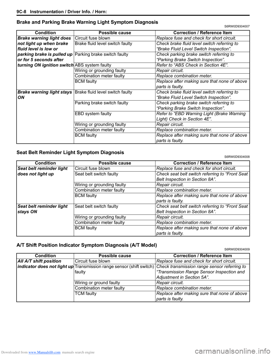
Brake and Parking Brake Warning Light Symptom DiagnosisS6RW0D9304007
Seat Belt Reminder Light Symptom DiagnosisS6RW0D9304008
A/T Shift Position Indicator Symptom Diagnosis (A/T Model)S6RW0D9304009
Condition Possible cause Correction / Reference Item
Brake warning light does
not light up when brake
fluid level is low or
parking brake is pulled up
or for 5 seconds after
turning ON ignition switchCircuit fuse blownReplace fuse and check for short circuit.
Brake fluid level switch faultyCheck brake fluid level switch referring to
“Brake Fluid Level Switch Inspection”.
Parking brake switch faultyCheck parking brake switch referring to
“Parking Brake Switch Inspection”.
ABS system faultyRefer to “ABS Check in Section 4E”.
Wiring or grounding faultyRepair circuit.
Combination meter faultyReplace combination meter.
BCM faultyReplace after making sure that none of above
parts is faulty.
Brake warning light stays
ONBrake fluid level switch faultyCheck brake fluid level switch referring to
“Brake Fluid Level Switch Inspection”.
Parking brake switch faultyCheck parking brake switch referring to
“Parking Brake Switch Inspection”.
EBD system faultyRefer to “EBD Warning Light (Brake Warning
Light) Check in Section 4E”.
Wiring or grounding faultyRepair circuit.
Combination meter faultyReplace combination meter.
BCM faultyReplace after making sure that none of above
parts is faulty.
Condition Possible cause Correction / Reference Item
Seat belt reminder light
does not light upCircuit fuse blownReplace fuse and check for short circuit.
Seat belt switch faultyCheck seat belt switch referring to “Front Seat
Belt Inspection in Section 8A”.
Wiring or grounding faultyRepair circuit.
Combination meter faultyReplace combination meter.
BCM faultyReplace after making sure that none of above
parts is faulty.
Seat belt reminder light
stays ONSeat belt switch faultyCheck seat belt switch referring to “Front Seat
Belt Inspection in Section 8A”.
Wiring or grounding faultyRepair circuit.
Combination meter faultyReplace combination meter.
BCM faultyReplace after making sure that none of above
parts is faulty.
Condition Possible cause Correction / Reference Item
All A/T shift position
indicator does not light upCircuit fuse blownReplace fuse and check for short circuit.
Transmission range sensor (shift switch)
faultyCheck transmission range sensor referring to
“Transmission Range Sensor Inspection and
Adjustment in Section 5A”.
Wiring or ground faultyRepair circuit.
Combination meter faultyReplace combination meter.
TCM faultyReplace after making sure that none of above
parts is faulty.
Page 1362 of 1556

Downloaded from www.Manualslib.com manuals search engine 9C-10 Instrumentation / Driver Info. / Horn:
Cigarette Lighter Symptom Diagnosis (If Equipped)S6RW0D9304013
Horn Symptom DiagnosisS6RW0D9304014
Information Display Symptom Diagnosis (If Equipped)S6RW0D9304015
NOTE
This thermometer indicates the ambient temperature in the under side of front bumper member. Under
any one of the following listed conditions, however, even when the ambient temperature goes up, the
thermometer display does not rise so as to correct the rise of the ambient temperature caused by the
radiant heat of the engine. When the ambient temperature drops, the thermometer reading follows the
change in the temperature.
Be sure to bear this in mind when diagnosing trouble.
• The vehicle speed is 30 km/h (18 mph) or lower.
• Vehicle speed signal is faulty.
• The ignition switch is turned on again within 2 hours.
Condition Possible cause Correction / Reference Item
Cigarette lighter shows
no operationCircuit fuse blownReplace fuse and check for short circuit.
Cigarette lighter faultyCheck cigarette lighter.
Ignition switch faultyCheck ignition switch referring to “Ignition
Switch Inspection”.
Wiring or grounding faultyRepair circuit.
Condition Possible cause Correction / Reference Item
Horn does not operateCircuit fuse blownReplace fuse and check for short circuit.
Horn switch faultyCheck horn switch.
Horn relay faultyCheck horn relay referring to “Horn Relay
Inspection”.
Wiring or grounding faultyRepair circuit.
Horn faultyCheck horn referring to “Horn Inspection”.
Condition Possible cause Correction / Reference Item
No displaying of
information displayCircuit fuse BlownReplace fuse and check for short circuit.
Wiring or grounding faultyRepair circuit.
Information display unit faultyReplace unit.
Incorrect thermometer
displayOutside air temperature sensor faultyCheck outside air temperature sensor referring
to “Outside Air Temperature Sensor Inspection
(If Equipped)”.
Vehicle speed signal faultyCheck ECM for DTC referring to “DTC Check
in Section 1A”.
Wiring or grounding faultyRepair circuit.
Information display unit faultyReplace unit.
BCM faultyReplace after making sure that none of above
parts is faulty.
Display of thermometer
does not change at –30
°C
(–22
°F)Outside air temperature is –30 °C (–22
°F) or less—
Outside air temperature sensor faultyCheck outside air temperature sensor referring
to “Outside Air Temperature Sensor Inspection
(If Equipped)”.
Information display unit faultyReplace unit.
BCM faultyReplace after making sure that none of above
parts is faulty.
Page 1363 of 1556
Downloaded from www.Manualslib.com manuals search engine Instrumentation / Driver Info. / Horn: 9C-11
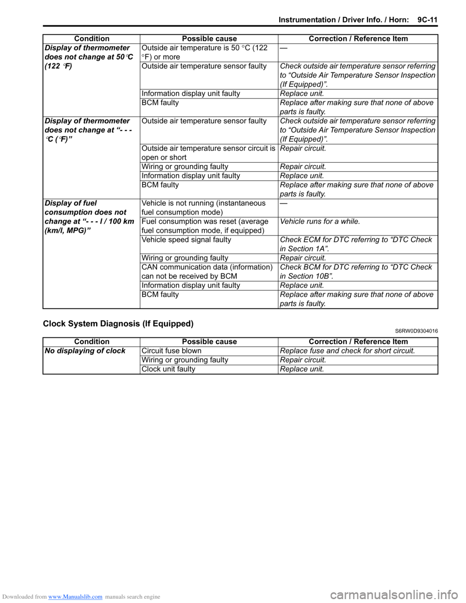
Clock System Diagnosis (If Equipped)S6RW0D9304016
Display of thermometer
does not change at 50
°C
(122
°F)Outside air temperature is 50 °C (122
°F) or more—
Outside air temperature sensor faultyCheck outside air temperature sensor referring
to “Outside Air Temperature Sensor Inspection
(If Equipped)”.
Information display unit faultyReplace unit.
BCM faultyReplace after making sure that none of above
parts is faulty.
Display of thermometer
does not change at “- - -
°C (°F)”Outside air temperature sensor faultyCheck outside air temperature sensor referring
to “Outside Air Temperature Sensor Inspection
(If Equipped)”.
Outside air temperature sensor circuit is
open or shortRepair circuit.
Wiring or grounding faultyRepair circuit.
Information display unit faultyReplace unit.
BCM faultyReplace after making sure that none of above
parts is faulty.
Display of fuel
consumption does not
change at “- - - l / 100 km
(km/l, MPG)”Vehicle is not running (instantaneous
fuel consumption mode)—
Fuel consumption was reset (average
fuel consumption mode, if equipped)Vehicle runs for a while.
Vehicle speed signal faultyCheck ECM for DTC referring to “DTC Check
in Section 1A”.
Wiring or grounding faultyRepair circuit.
CAN communication data (information)
can not be received by BCMCheck BCM for DTC referring to “DTC Check
in Section 10B”.
Information display unit faultyReplace unit.
BCM faultyReplace after making sure that none of above
parts is faulty. Condition Possible cause Correction / Reference Item
Condition Possible cause Correction / Reference Item
No displaying of clockCircuit fuse blownReplace fuse and check for short circuit.
Wiring or grounding faultyRepair circuit.
Clock unit faultyReplace unit.
Page 1367 of 1556
Downloaded from www.Manualslib.com manuals search engine Instrumentation / Driver Info. / Horn: 9C-15
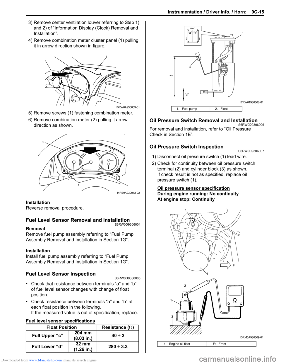
3) Remove center ventilation louver referring to Step 1)
and 2) of “Information Display (Clock) Removal and
Installation”.
4) Remove combination meter cluster panel (1) pulling
it in arrow direction shown in figure.
5) Remove screws (1) fastening combination meter.
6) Remove combination meter (2) pulling it arrow
direction as shown.
Installation
Reverse removal procedure.
Fuel Level Sensor Removal and InstallationS6RW0D9306004
Removal
Remove fuel pump assembly referring to “Fuel Pump
Assembly Removal and Installation in Section 1G”.
Installation
Install fuel pump assembly referring to “Fuel Pump
Assembly Removal and Installation in Section 1G”.
Fuel Level Sensor InspectionS6RW0D9306005
• Check that resistance between terminals “a” and “b”
of fuel level sensor changes with change of float
position.
• Check resistance between terminals “a” and “b” at
each float position in the following.
If the measured value is out of specification, replace.
Fuel level sensor specifications
Oil Pressure Switch Removal and InstallationS6RW0D9306006
For removal and installation, refer to “Oil Pressure
Check in Section 1E”.
Oil Pressure Switch InspectionS6RW0D9306007
1) Disconnect oil pressure switch (1) lead wire.
2) Check for continuity between oil pressure switch
terminal (2) and cylinder block (3) as shown.
If check result is not as specified, replace oil
pressure switch (1).
Oil pressure sensor specification
During engine running: No continuity
At engine stop: Continuity
Float Position Resistance (Ω)
Full Upper “c”204 mm
(8.03 in.)40 ± 2
Full Lower “d”32 mm
(1.26 in.)280 ± 3.3
1
I5RW0A930009-01
1
2
I4RS0A930012-02
1. Fuel pump 2. Float
4. Engine oil filter F: Front
“c”
“d”
“b” “a”1
2
I7RW01930008-01
I3RM0A930009-01
Page 1368 of 1556

Downloaded from www.Manualslib.com manuals search engine 9C-16 Instrumentation / Driver Info. / Horn:
Engine Coolant Temperature (ECT) Sensor
Inspection
S6RW0D9306008
Check engine coolant temperature sensor for resistance,
refer to “Engine Coolant Temperature (ECT) Sensor
Inspection in Section 1C”.
Brake Fluid Level Switch InspectionS6RW0D9306009
Check for continuity between terminals of brake fluid
level switch coupler (1). If found defective, replace
switch.
Brake fluid level switch specification
OFF position (float up): No continuity
ON position (float down): Continuity
Parking Brake Switch InspectionS6RW0D9306010
Check for continuity between parking brake switch
terminal and body ground as shown in figure. If found
defective, replace switch.
Parking brake switch specification
OFF position (parking brake released): No continuity
ON position (parking brake lever pulled up):
Continuity
Door Switch (Front / Rear Door) InspectionS6RW0D9306011
Remove door switch from body and check switch for
continuity. If found defective, replace switch.
Door switch (front / rear door) specification
OFF position (Door closed): No continuity
ON position (Door open): Continuity
Rear End Door Switch InspectionS6RW0D9306012
Check for continuity between terminal “a” and “b” shown
in the following.
If check result is not as specified, replace switch.
Rear end door switch specification
Rear end door closed: No continuity
Rear end door opened: Continuity
1. Parking brake switch 2. Parking brake lever
1
I5RW0A930011-01
12
I4RS0A930014-01
I3RH0A930004-01
a
b
I4RS0A930015-01
Page 1369 of 1556
Downloaded from www.Manualslib.com manuals search engine Instrumentation / Driver Info. / Horn: 9C-17
Outside Air Temperature Sensor Removal and
Installation (If Equipped)
S6RW0D9306013
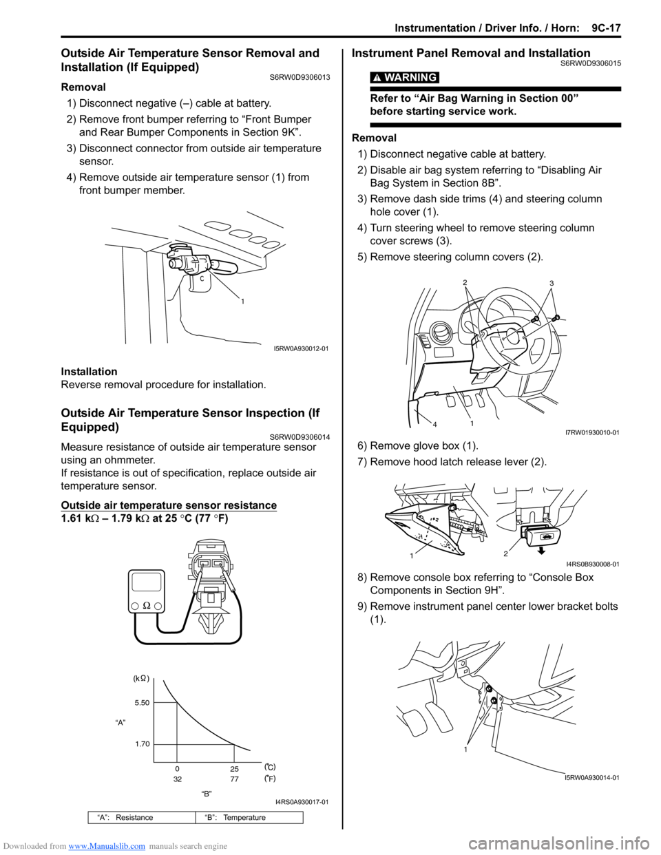
Removal
1) Disconnect negative (–) cable at battery.
2) Remove front bumper referring to “Front Bumper
and Rear Bumper Components in Section 9K”.
3) Disconnect connector from outside air temperature
sensor.
4) Remove outside air temperature sensor (1) from
front bumper member.
Installation
Reverse removal procedure for installation.
Outside Air Temperature Sensor Inspection (If
Equipped)
S6RW0D9306014
Measure resistance of outside air temperature sensor
using an ohmmeter.
If resistance is out of specification, replace outside air
temperature sensor.
Outside air temperature sensor resistance
1.61 kΩ – 1.79 kΩ at 25 °C (77 °F)
Instrument Panel Removal and InstallationS6RW0D9306015
WARNING!
Refer to “Air Bag Warning in Section 00”
before starting service work.
Removal
1) Disconnect negative cable at battery.
2) Disable air bag system referring to “Disabling Air
Bag System in Section 8B”.
3) Remove dash side trims (4) and steering column
hole cover (1).
4) Turn steering wheel to remove steering column
cover screws (3).
5) Remove steering column covers (2).
6) Remove glove box (1).
7) Remove hood latch release lever (2).
8) Remove console box referring to “Console Box
Components in Section 9H”.
9) Remove instrument panel center lower bracket bolts
(1).
“A”: Resistance “B”: Temperature
1
I5RW0A930012-01
“B” “A”5.50
1.70
0
3225
77
F
I4RS0A930017-01
2
3
1
4I7RW01930010-01
2
1I4RS0B930008-01
1
I5RW0A930014-01
Page 1387 of 1556
Downloaded from www.Manualslib.com manuals search engine Glass / Windows / Mirrors: 9E-2
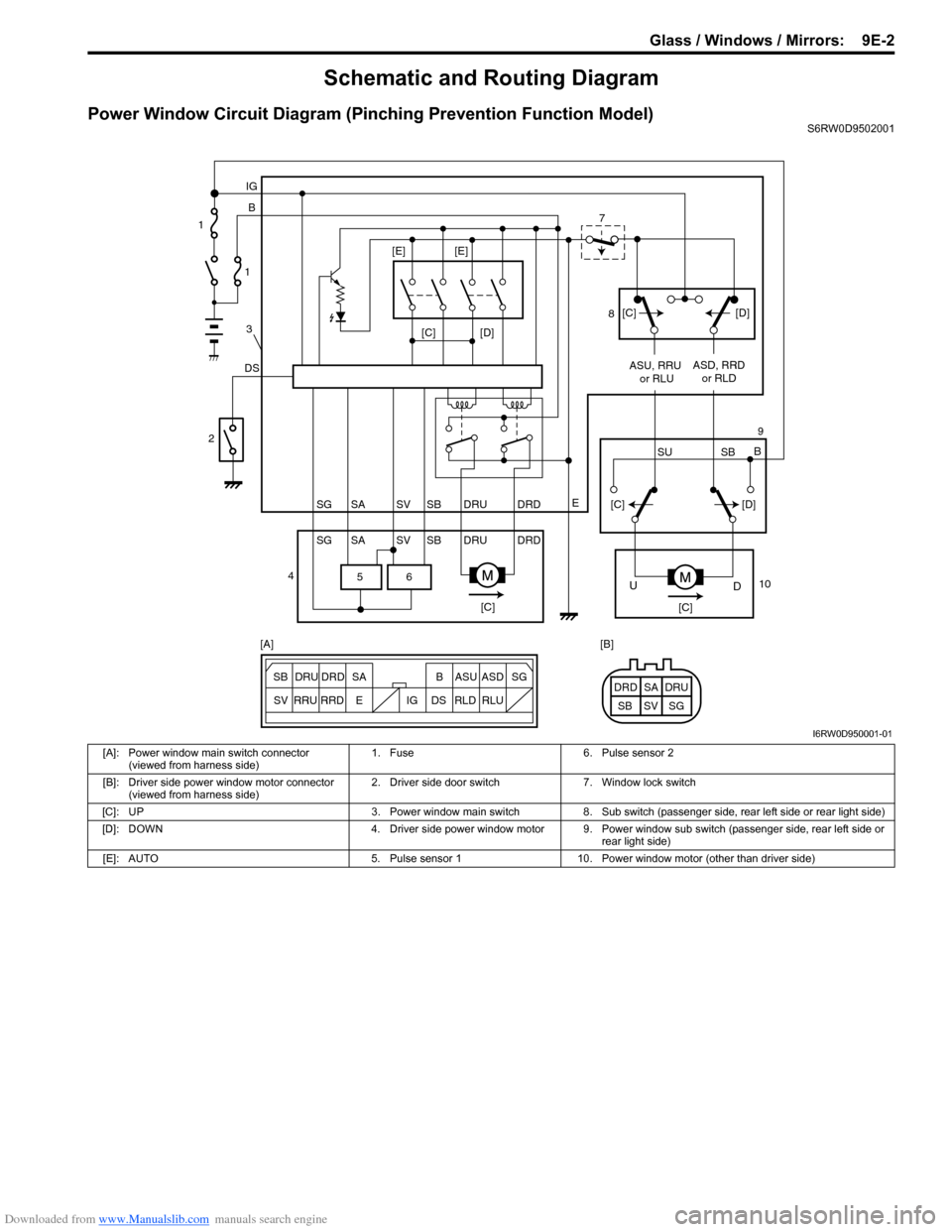
Schematic and Routing Diagram
Power Window Circuit Diagram (Pinching Prevention Function Model)S6RW0D9502001
6 5
[C][D]
DSB IG
E
SG SV SBSA DRU DRD
SG SV SBSA DRU DRDASU, RRU
or RLUASD, RRD
or RLD
[C][C]
D U
[C][D]
SU SBB [C][D] [E] [E]
ESG
SV SB SADRU DRD B ASU ASD
RRU
RRDDS IG RLD RLUSG SV SBSA DRU DRD [A] [B] 1
1
3
2
47
8
9
10
I6RW0D950001-01
[A]: Power window main switch connector
(viewed from harness side)1. Fuse 6. Pulse sensor 2
[B]: Driver side power window motor connector
(viewed from harness side)2. Driver side door switch 7. Window lock switch
[C]: UP 3. Power window main switch 8. Sub switch (passenger side, rear left side or rear light side)
[D]: DOWN 4. Driver side power window motor 9. Power window sub switch (passenger side, rear left side or
rear light side)
[E]: AUTO 5. Pulse sensor 1 10. Power window motor (other than driver side)
Page 1388 of 1556

Downloaded from www.Manualslib.com manuals search engine 9E-3 Glass / Windows / Mirrors:
Diagnostic Information and Procedures
Rear End door Window Defogger Symptom DiagnosisS6RW0D9504001
NOTE
• Use of SUZUKI scan tool makes it easy to check whether a faulty condition is on the input side or
output side of BCM. For checking procedure, refer to “Diagnosis Using Output Test Function of
SUZUKI Scan Tool” under “Scan Tool Data in Section 10B”.
• Check each part in the order from the top of the following list.
Power Window Control System Symptom DiagnosisS6RW0D9504002
Condition Possible cause Correction / Reference Item
Rear end door window
defogger does not
operateCircuit fuse blownReplace fuse and check for short circuit.
Rear end door window defogger switch
faultyCheck rear end door window defogger switch
referring to “Rear End Door Window Defogger
Switch Inspection”.
Rear end door window defogger relay
faultyCheck rear end door window defogger relay
referring to “Rear End Door Window Defogger
Relay Inspection”.
Defogger wire faultyCheck defogger wire referring to “Rear End
Door Window Defogger Wire Inspection”.
Wiring or grounding faultyRepair circuit.
BCM faultyReplace after making sure that none of above
parts is faulty.
Condition Possible cause Correction / Reference Item
All power windows do not
operateCircuit fuse blownReplace fuse and check for short circuit.
Power window main switch faultyCheck power window main switch referring to
“Power Window Main Switch Inspection”.
Ignition switch faultyCheck ignition switch referring to “Ignition
Switch Inspection in Section 9C”.
Wiring or grounding faultyRepair circuit.
Only one power window
does not operatePower window main switch faultyCheck power window main switch referring to
“Power Window Main Switch Inspection”.
Power window sub switch faultyCheck power window sub switch referring to
“Power Window Sub Switch Inspection”.
Wiring and/or coupler faultyCheck wiring and/or coupler.
Power window regulator faultyCheck window regulator.
Power window motor faultyCheck power window motor.
Wiring or grounding faultyRepair circuit.
Driver side door glass
fails to perform auto-up /
auto-down function
(Pinching Prevention
Function Model)Power window main switch faultyCheck power window main switch referring to
“Power Window Main Switch Inspection”.
Power window motor faultyCheck power window motor referring to “Pulse
Sensor and Its Circuit Inspection (Pinching
Prevention Function Model)”.
Wiring or grounding faultyRepair circuit.
Driver side door glass
fails to lower back even
when a foreign matter is
pinched (Pinching
Prevention Function
Model)Power window main switch has not been
initializedExecute the initial setting of power window
main switch referring to “Power Window Main
Switch Initialization (Pinching Prevention
Function Model)”.
Power window main switch faultyCheck power window main switch referring to
“Power Window Main Switch Inspection”.
Power window motor faultyCheck power window motor referring to “Pulse
Sensor and Its Circuit Inspection (Pinching
Prevention Function Model)”.