front light SUZUKI SX4 2006 1.G Service Repair Manual
[x] Cancel search | Manufacturer: SUZUKI, Model Year: 2006, Model line: SX4, Model: SUZUKI SX4 2006 1.GPages: 1556, PDF Size: 37.31 MB
Page 1217 of 1556
Downloaded from www.Manualslib.com manuals search engine Wiring Systems: 9A-50
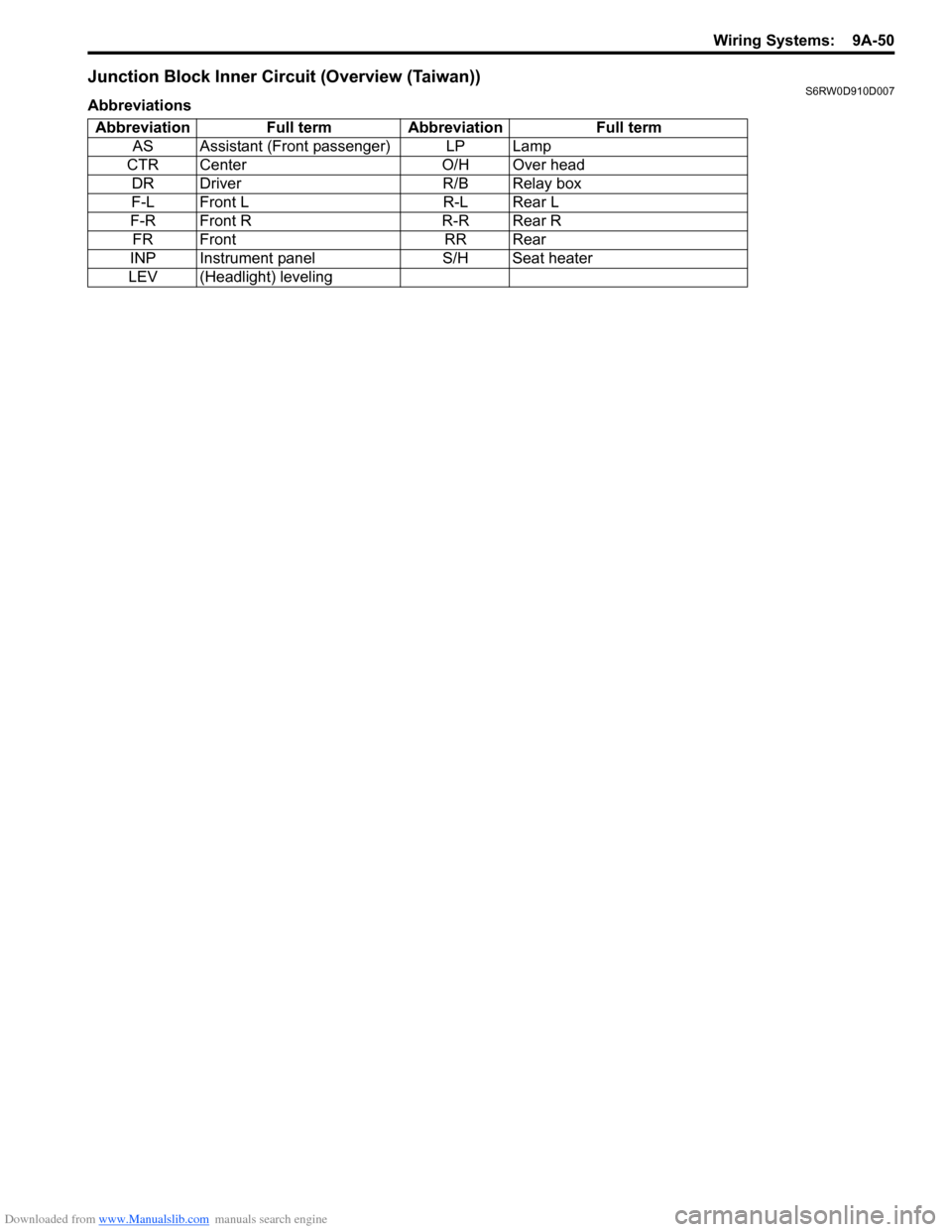
Junction Block Inner Circuit (Overview (Taiwan))S6RW0D910D007
Abbreviations
Abbreviation Full term Abbreviation Full term
AS Assistant (Front passenger) LP Lamp
CTR Center O/H Over head
DR Driver R/B Relay box
F-L Front L R-L Rear L
F-R Front R R-R Rear R
FR Front RR Rear
INP Instrument panel S/H Seat heater
LEV (Headlight) leveling
Page 1224 of 1556
Downloaded from www.Manualslib.com manuals search engine 9A-57 Wiring Systems:
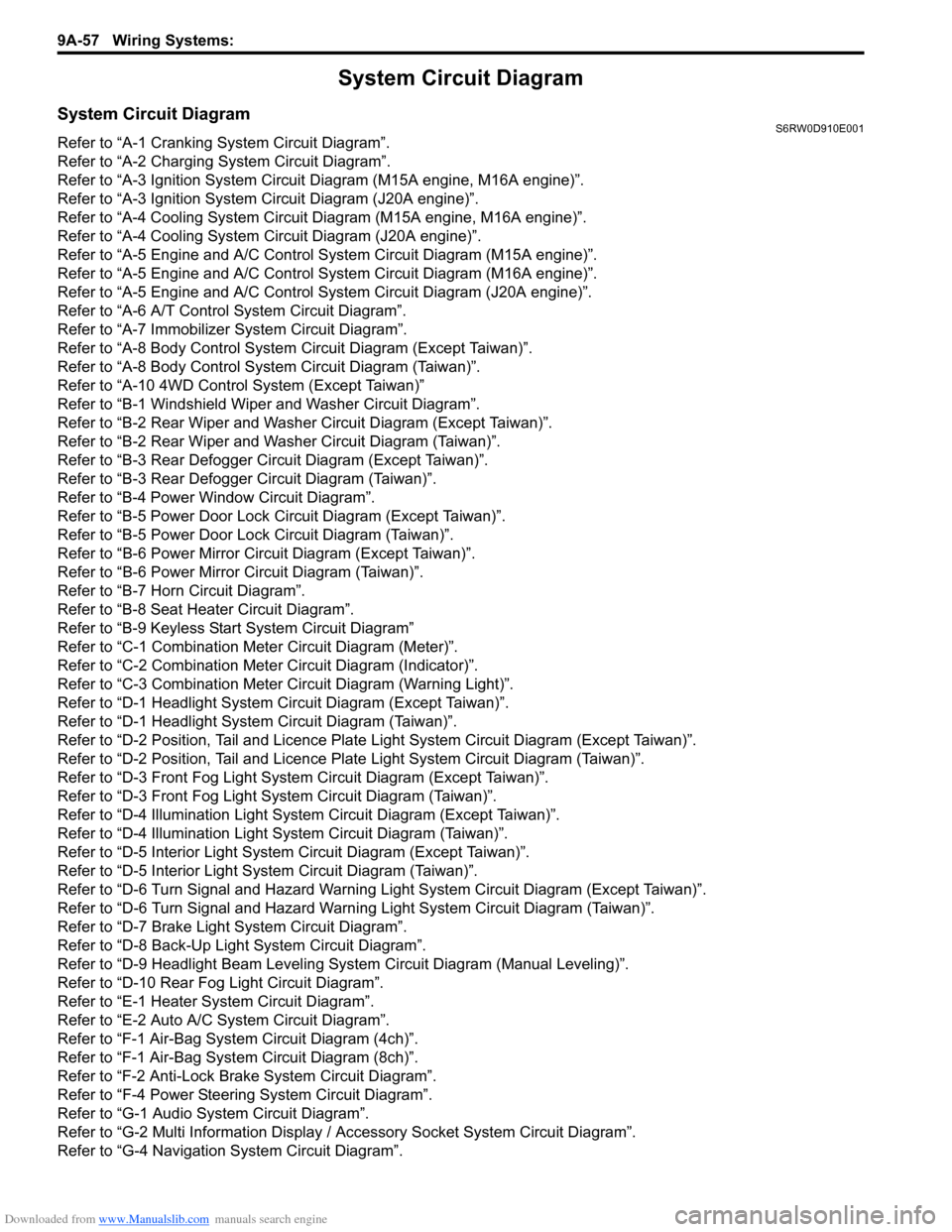
System Circuit Diagram
System Circuit DiagramS6RW0D910E001
Refer to “A-1 Cranking System Circuit Diagram”.
Refer to “A-2 Charging System Circuit Diagram”.
Refer to “A-3 Ignition System Circuit Diagram (M15A engine, M16A engine)”.
Refer to “A-3 Ignition System Circuit Diagram (J20A engine)”.
Refer to “A-4 Cooling System Circuit Diagram (M15A engine, M16A engine)”.
Refer to “A-4 Cooling System Circuit Diagram (J20A engine)”.
Refer to “A-5 Engine and A/C Control System Circuit Diagram (M15A engine)”.
Refer to “A-5 Engine and A/C Control System Circuit Diagram (M16A engine)”.
Refer to “A-5 Engine and A/C Control System Circuit Diagram (J20A engine)”.
Refer to “A-6 A/T Control System Circuit Diagram”.
Refer to “A-7 Immobilizer System Circuit Diagram”.
Refer to “A-8 Body Control System Circuit Diagram (Except Taiwan)”.
Refer to “A-8 Body Control System Circuit Diagram (Taiwan)”.
Refer to “A-10 4WD Control System (Except Taiwan)”
Refer to “B-1 Windshield Wiper and Washer Circuit Diagram”.
Refer to “B-2 Rear Wiper and Washer Circuit Diagram (Except Taiwan)”.
Refer to “B-2 Rear Wiper and Washer Circuit Diagram (Taiwan)”.
Refer to “B-3 Rear Defogger Circuit Diagram (Except Taiwan)”.
Refer to “B-3 Rear Defogger Circuit Diagram (Taiwan)”.
Refer to “B-4 Power Window Circuit Diagram”.
Refer to “B-5 Power Door Lock Circuit Diagram (Except Taiwan)”.
Refer to “B-5 Power Door Lock Circuit Diagram (Taiwan)”.
Refer to “B-6 Power Mirror Circuit Diagram (Except Taiwan)”.
Refer to “B-6 Power Mirror Circuit Diagram (Taiwan)”.
Refer to “B-7 Horn Circuit Diagram”.
Refer to “B-8 Seat Heater Circuit Diagram”.
Refer to “B-9 Keyless Start System Circuit Diagram”
Refer to “C-1 Combination Meter Circuit Diagram (Meter)”.
Refer to “C-2 Combination Meter Circuit Diagram (Indicator)”.
Refer to “C-3 Combination Meter Circuit Diagram (Warning Light)”.
Refer to “D-1 Headlight System Circuit Diagram (Except Taiwan)”.
Refer to “D-1 Headlight System Circuit Diagram (Taiwan)”.
Refer to “D-2 Position, Tail and Licence Plate Light System Circuit Diagram (Except Taiwan)”.
Refer to “D-2 Position, Tail and Licence Plate Light System Circuit Diagram (Taiwan)”.
Refer to “D-3 Front Fog Light System Circuit Diagram (Except Taiwan)”.
Refer to “D-3 Front Fog Light System Circuit Diagram (Taiwan)”.
Refer to “D-4 Illumination Light System Circuit Diagram (Except Taiwan)”.
Refer to “D-4 Illumination Light System Circuit Diagram (Taiwan)”.
Refer to “D-5 Interior Light System Circuit Diagram (Except Taiwan)”.
Refer to “D-5 Interior Light System Circuit Diagram (Taiwan)”.
Refer to “D-6 Turn Signal and Hazard Warning Light System Circuit Diagram (Except Taiwan)”.
Refer to “D-6 Turn Signal and Hazard Warning Light System Circuit Diagram (Taiwan)”.
Refer to “D-7 Brake Light System Circuit Diagram”.
Refer to “D-8 Back-Up Light System Circuit Diagram”.
Refer to “D-9 Headlight Beam Leveling System Circuit Diagram (Manual Leveling)”.
Refer to “D-10 Rear Fog Light Circuit Diagram”.
Refer to “E-1 Heater System Circuit Diagram”.
Refer to “E-2 Auto A/C System Circuit Diagram”.
Refer to “F-1 Air-Bag System Circuit Diagram (4ch)”.
Refer to “F-1 Air-Bag System Circuit Diagram (8ch)”.
Refer to “F-2 Anti-Lock Brake System Circuit Diagram”.
Refer to “F-4 Power Steering System Circuit Diagram”.
Refer to “G-1 Audio System Circuit Diagram”.
Refer to “G-2 Multi Information Display / Accessory Socket System Circuit Diagram”.
Refer to “G-4 Navigation System Circuit Diagram”.
Page 1249 of 1556
Downloaded from www.Manualslib.com manuals search engine Wiring Systems: 9A-82
3
A
AG2716L312
13
J/C
G309
BLK/ORNBLK/ORN
4L314
16
BLK/ORN
C
C
J/C
G308
C
C
J/C
L346
YEL
"A-2" GeneratorRHD"D-5" Spot
light"D-5" Interior light
E044
WHT/BLU
WB
WHT/REDWHT/RED
WHT/RED
WRWR
11YEL
Y
GRY
8G04
G
"G-2" Multi
information
display
BCM
Auto
unit
"E-2"
J/B
A3142
5
WHT
W
7
2L313
YEL
Y
9
7G272
RED/YEL
RY
16E325
RED/YEL
RY
3L314
RED/YELRED/YEL
RED/YEL
RED/YEL
RY
RYRYRY
3
PPL/WHT
PW
8
J/B side connector (BCM) A
"F-1"
A/B
SDMFront
position
light
"D-2"
A/T shift
lever
"D-4"
"D-2"
Tail light (L) Tail light (R)Licence plate light
"D-2"
"D-2"I6RW0C910954-01
Page 1278 of 1556
Downloaded from www.Manualslib.com manuals search engine 9A-111 Wiring Systems:
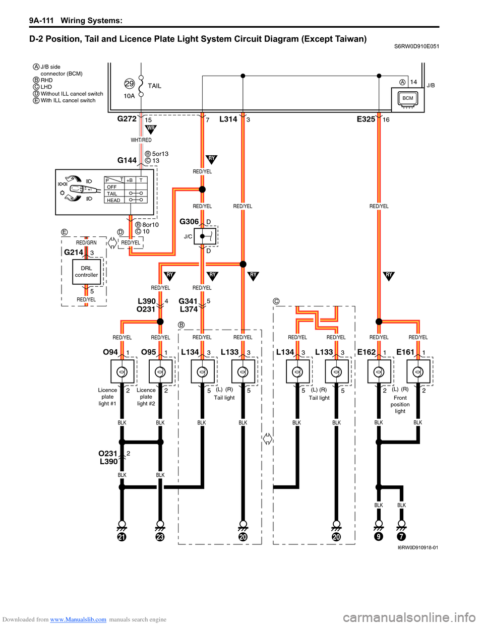
D-2 Position, Tail and Licence Plate Light System Circuit Diagram (Except Taiwan)S6RW0D910E051
3
5L1341
2O951
2O94
(R) (L)
(L)
(R)
BLK
715G272
G144
10ATAIL
29
1
2E1611
2E162
BLKBLK
BLKBLK
BLK
J/B
L3143E32516
BLKBLK
Licence
plate
light #2 Licence
plate
light #1
3
5L133
BLK
972320
BLK
21
WHT/RED
OFF
TAIL
HEAD+BT T
P
Front
position
light
RED/YEL
RED/YEL
RED/YEL
RED/YELRED/YEL
Tail light
RY
RYRY
WR
RYRY
RED/YEL
RED/YELRED/YEL
RED/YELRED/YELRED/YELRED/YELRED/YEL
4L390
O2315G341
L374
2O231
L390
J/C
G306D
D
5or13
13BC
8or10
10BC
J/B side
connector (BCM)
RHD
LHD
Without ILL cancel switch
With ILL cancel switch A
B
B
3
5L133
(L)
(R)
BLK
3
5L134
BLK
20
Tail light
RED/YELRED/YEL
C
CDE
14
BCM
A
DRL
controller
G2143
5
RED/YEL
RED/GRN
ED
I6RW0D910918-01
Page 1279 of 1556

Downloaded from www.Manualslib.com manuals search engine Wiring Systems: 9A-112
D-2 Position, Tail and Licence Plate Light System Circuit Diagram (Taiwan)S6RW0D910E023
3
5L1341
2O951
2O94
(R) (L)
(R)
(L)
BLK
18712G272
10
11
BLK
G14413
G05
G0412
10ATAIL
36
1
2E1611
2E162
BLKBLK
BLKBLK
BLK
J/B
L3143E32516
BLKBLK
Licence
plate
light #2 Licence
plate
light #1
3
5L133
BLK
13972320
BLK
21
BLU/WHT
RED/YEL
OFF
TAIL
HEAD+BT T
P
Front
position
light
RED/YEL
RED/YELRED/YELRED/YEL
RED/YEL
Tail light
RY
RYRY
RY
RYRY
RED/YEL
RED/YELRED/YEL
RED/YELRED/YELRED/YELRED/YELRED/YEL
4L390
O2315G341
L374
2O231
L390
BCM
J/C
G306D
D
2 1
3
4
Tail light
relay
I6RW0C910980-01
Page 1280 of 1556

Downloaded from www.Manualslib.com manuals search engine 9A-113 Wiring Systems:
D-3 Front Fog Light System Circuit Diagram (Except Taiwan)S6RW0D910E052
FR
FOG
(R) (L)
2
E1641
2
E1631
20A
14
Relay
Switch
3
E2342
14
WHT/GRNGRY/RED
LT GRN
BLK
BLKBLK
LT GRNLT GRN
1
D
DG334
E382
FREEIG LOAD E Il Ile
TERMINAL
POSITION
PUSH
6 7
4
8
G306
G151
RED/YEL
RED/YELGRY/REDRED/YEL
RED/YEL
11
BLK
BLK
RED/BLU
RED/BLU
5
J/C
B
BG309
J/C
A
A
C
CG306
J/C
BLK
BLK
RY"D-4"
BLKBLK
BLK
14
Individual circuit
fuse box (No.1)
9
BLK
7I6RW0C910983-01
Page 1281 of 1556

Downloaded from www.Manualslib.com manuals search engine Wiring Systems: 9A-114
D-3 Front Fog Light System Circuit Diagram (Taiwan)S6RW0D910E024
FR
FOG
(R) (L)
2
E1641
2
E1631
20A
14
Relay
Switch
3
E2342
14
WHT/GRNRED/YEL
RED/YEL
LT GRN
BLK
BLKBLK
LT GRNLT GRN
14
D
DG333
E381
13E381
G333
FREEIG LOAD E Il Ile
TERMINAL
POSITION
PUSH
7 6
4
8
G306
G151
RED/YEL
RED/YELGRY/REDRED/YEL
RED/YEL
11
BLK/YEL
BLK/YEL
5
J/C
B
BG309
J/C
A
AG306
J/C J/B
BLK
BLK
BLK
BLK
RY"D-4"GR
B
"A-8"
BLKBLK
BLK
14
Individual circuit
fuse box (No.1)
9
BLK
7
BCM
"A-8"
BCM
I6RW0C910982-01
Page 1282 of 1556
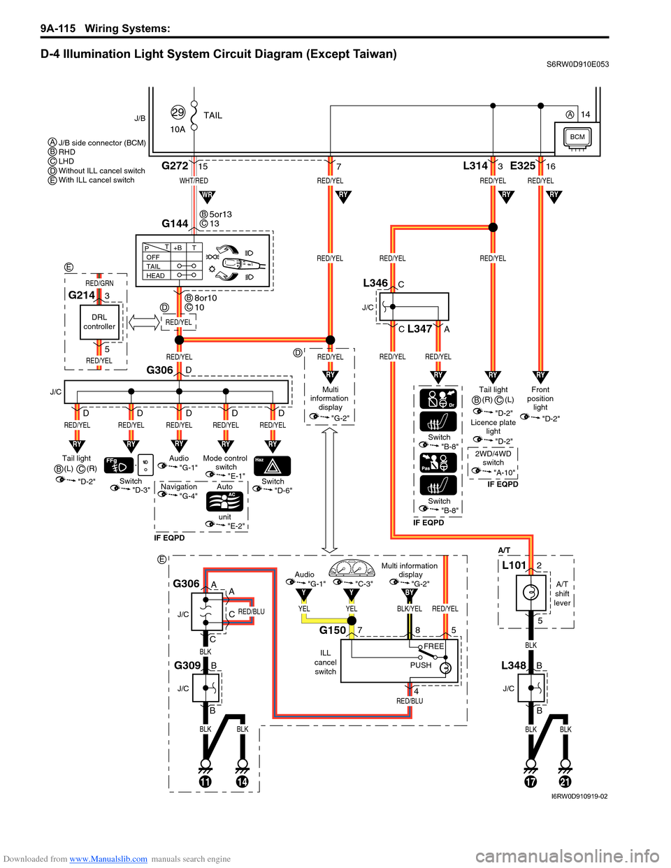
Downloaded from www.Manualslib.com manuals search engine 9A-115 Wiring Systems:
D-4 Illumination Light System Circuit Diagram (Except Taiwan)S6RW0D910E053
BLKBLK
BLK
RED/BLU
RED/BLU
11
J/C
J/C
B
B
14
G309
A
A
C
CG306
BLK/YELRED/YEL
BY
YELYEL
YY
Multi information
display
"G-2"Audio
"G-1""C-3"
ILL
cancel
switch
G150758
4
PUSHFREE
WHT/RED
10ATAIL
29J/B
15G272
G144
1721
RED/YELRED/YELRED/YEL
RED/YELRED/YEL
L3143
BLKBLK
BLK
"D-3"
A/T
RY
Switch
J/C
G306
RED/YEL
RY
RED/YEL
Switch
Auto
unit
IF EQPDIF EQPDIF EQPD
RY
RED/YEL
Mode control
switch
"E-1"Tail light
(L)
"D-2"
"E-2"
"D-6"Switch"B-8"
Switch"B-8"
OFF
TAIL
HEAD+BT T
P
7
RY
RED/YEL
Audio
"G-1"
Navigation
"G-4"
D
D
D D D
RY
RED/YEL
D
RED/YEL
Multi
information
display
"G-2"
RED/YEL
RYRYRY
RYRYWR
Tail light
"D-2"Front
position
light
"D-2"
Licence plate
light
"D-2"
2WD/4WD
switch
"A-10"
RED/YELRED/YEL
RED/YEL
E32516
RY
RY
J/C
B
BL348
J/C
C
C
A
L346
L347
A/T
shift
lever
L1012
5
5or13
13BC
8or10
10BC
J/B side connector (BCM)
RHD
LHD
Without ILL cancel switch
With ILL cancel switch ABCDE
B(R)
C
(R)
B(L)
C
BCM
14A
RED/YEL
D
D
E
DRL
controller
G2143
5
RED/YEL
RED/GRN
E
I6RW0D910919-02
Page 1283 of 1556

Downloaded from www.Manualslib.com manuals search engine Wiring Systems: 9A-116
D-4 Illumination Light System Circuit Diagram (Taiwan)S6RW0D910E025
BLU/WHT
RED/YEL
10ATAIL
36
J/B
12G272
10
G14413
131721
RED/YELRED/YEL
RED/YELRED/YELRED/YEL
L3143
BLKBLK
BLKBLK
"D-3"
A/T
RY
Switch
J/C
G306
RED/YEL
RY
RED/YEL
Switch
Auto
unit
RY
RED/YEL
Mode control
switch
"E-1"Tail light
(R)
"D-2"
"E-2"
"D-6"
OFF
TAIL
HEAD+BT T
P
187
RY
RED/YEL
Audio
"G-1"
D
D
D D D
RY
RED/YEL
D
RED/YEL
Multi
information
display
"G-2"
RED/YEL
RYRY
RYRY
RY
Tail light (L)
"D-2"Front
position
light
"D-2"
Licence plate
light
"D-2"
RED/YEL
RED/YEL
E32516
RY
RY
J/C
B
BL348
J/C
C
CL346
A/T
shift
lever
L1012
5
2 1
3
4
Tail light
relay
11
G05
G0412
BCM
I6RW0C910985-01
Page 1284 of 1556
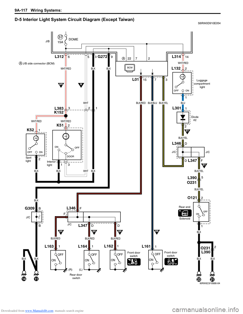
Downloaded from www.Manualslib.com manuals search engine 9A-117 Wiring Systems:
D-5 Interior Light System Circuit Diagram (Except Taiwan)S6RW0D910E054
15A
37DOMEJ/B
OFF
DOOR ON
ON OFF
K51 L3122 6
3
1Interior
light Spot
light
OFF
ON
OFF
ON
L1611 1
BLK
BLK
BLKOFF
ONOFF
ON
L164L1621L1631
Rear door
switchFront door
switch
BLK
BLK
BLKBLKWHTBLK
WHT
BLKBLK
G2729L31414
15L0173
WHT/RED
WHT/REDWHT/RED
G309
J/C
B
B
3
Luggage
compartment
light
2
1L132
WHT/RED
BLK/YEL
BLUBLK/YELBLK/BLUBLK/RED
112321
OFF
ON
O1212
L390
O2315
1
BLK/YEL
BLK/YEL
5
Solenoid
L346
L347
J/C
F
F
D
D
(R) (L)Front door
switch
BLK/REDBLK/REDBLK/RED
Rear end
BRBRBRBB
14
BLK
WWR
BY
BY
BCM
ON OFF
1
2K52
Diode
#2
1L301
2
D
D
F
J/C
J/C
L346
L347
O231
L3902
L383
K152321
22 7 2A
J/B side connector (BCM) A
I6RW0C910986-04