front light SUZUKI SX4 2006 1.G Service Repair Manual
[x] Cancel search | Manufacturer: SUZUKI, Model Year: 2006, Model line: SX4, Model: SUZUKI SX4 2006 1.GPages: 1556, PDF Size: 37.31 MB
Page 1285 of 1556
Downloaded from www.Manualslib.com manuals search engine Wiring Systems: 9A-118
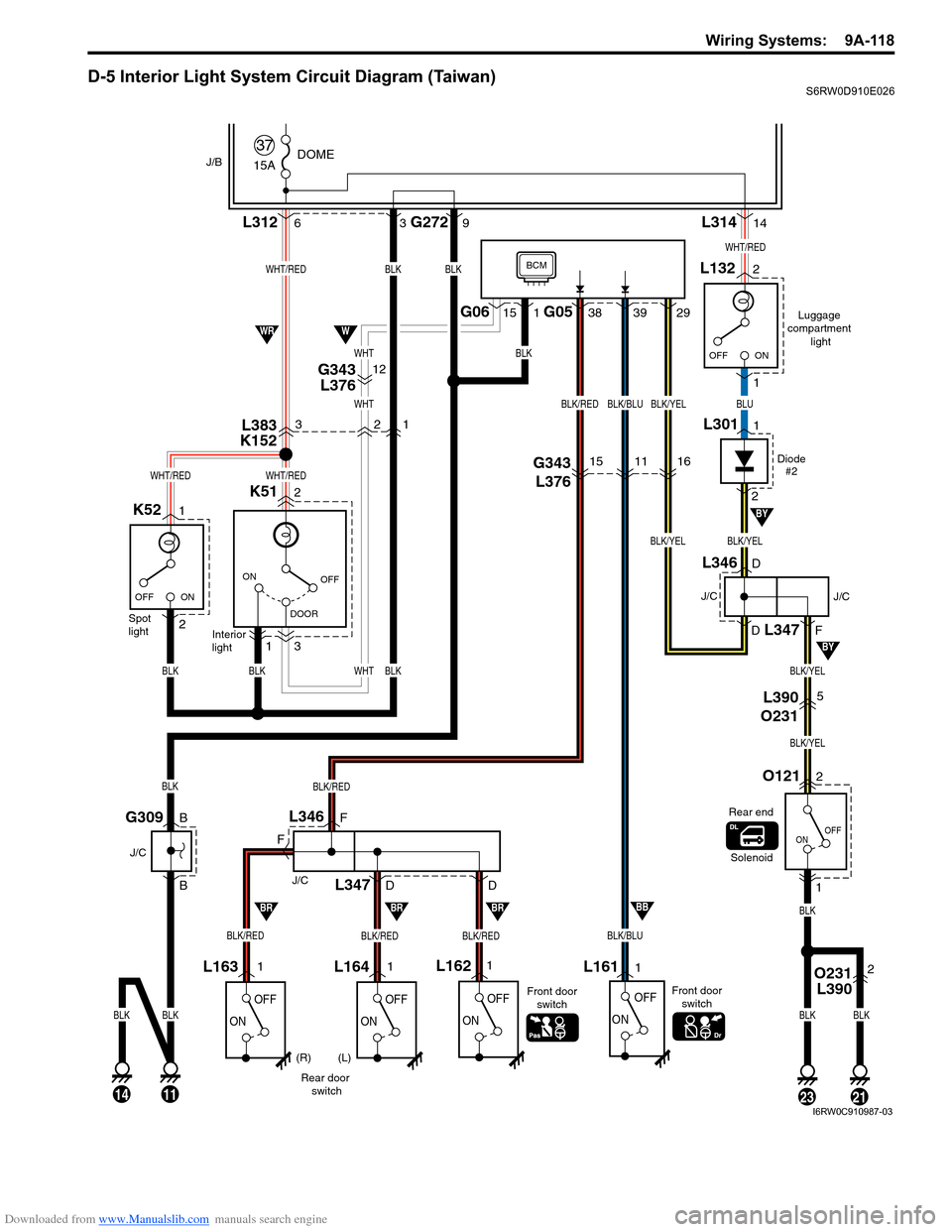
D-5 Interior Light System Circuit Diagram (Taiwan)S6RW0D910E026
15A
37DOMEJ/B
OFF
DOOR ON
ON OFF
K51 L3122 6
3
1Interior
light Spot
light
OFF
ON
OFF
ON
L1611 1
BLK/BLU
BLK
BLK
BLKOFF
ONOFF
ON
L164L1621L1631
Rear door
switchFront door
switch
BLK/RED
BLK
BLK
BLKBLKWHTBLK
WHT
WHTBLK
BLKBLK
G2729L31414
38G06 G051513929
WHT/RED
WHT/REDWHT/RED
G309
J/C
B
B
3
Luggage
compartment
light
2
1L132
WHT/RED
BLK/YELBLK/YEL
BLUBLK/YELBLK/BLUBLK/RED
112321
OFF
ON
O1212
L390
O2315
G343
L376151116
1
BLK/YEL
BLK/YEL
Solenoid
L346
L347
J/C
F
F
D
D
(R) (L)Front door
switch
BLK/REDBLK/REDBLK/RED
Rear end
BRBRBRBB
14
BLK
WWR
BY
BY
BCM
ON OFF
1
2K52
Diode
#2
1L301
2
D
D
F
J/C
J/C
L346
L347
O231
L3902
L383
K1523
G343
L37612
21
I6RW0C910987-03
Page 1287 of 1556
Downloaded from www.Manualslib.com manuals search engine Wiring Systems: 9A-120
9
GRN/RED
GRN/REDGRN/RED
9
Turn (L) Turn (R)
E165
12G2716
BLU/YEL
BLU/YELBLU/YEL
GRN/REDBLU/YEL
"C-2"
GRBY
Front turn
signal light (R) Side turn signal
light (R)
E159
2E166
Front turn
signal light (L) Side turn signal
light (L)
BLK
E3235
BLKBLK
BLKBLK
12
1
2
12
1
E160
1
2
J/B
I6RW0C910989-01
Page 1289 of 1556
Downloaded from www.Manualslib.com manuals search engine Wiring Systems: 9A-122
9
GRN/RED
GRN/REDGRN/RED
9
Turn (L) Turn (R)
E165
12G2716
BLU/YEL
BLU/YELBLU/YEL
GRN/REDBLU/YEL
"C-2"
GRBY
Front turn
signal light (R) Side turn signal
light (R)
E159
2E166
Front turn
signal light (L) Side turn signal
light (L)
BLK
E3235
BLKBLK
BLKBLK
12
1
2
12
1
E160
1
2
J/B
I6RW0C910991-01
Page 1321 of 1556
Downloaded from www.Manualslib.com manuals search engine Lighting Systems: 9B-2
Igniter
Igniter generates high voltage needed to turn on the discharge headlight. It is charged with high voltage raised by the
ballast and it applies voltage pulse as high as about 20,000V to the tungsten electrode in the discharge headlight bulb.
After the discharge headlights light up, the ballast supplies voltage to bulbs.
Discharge headlight bulb
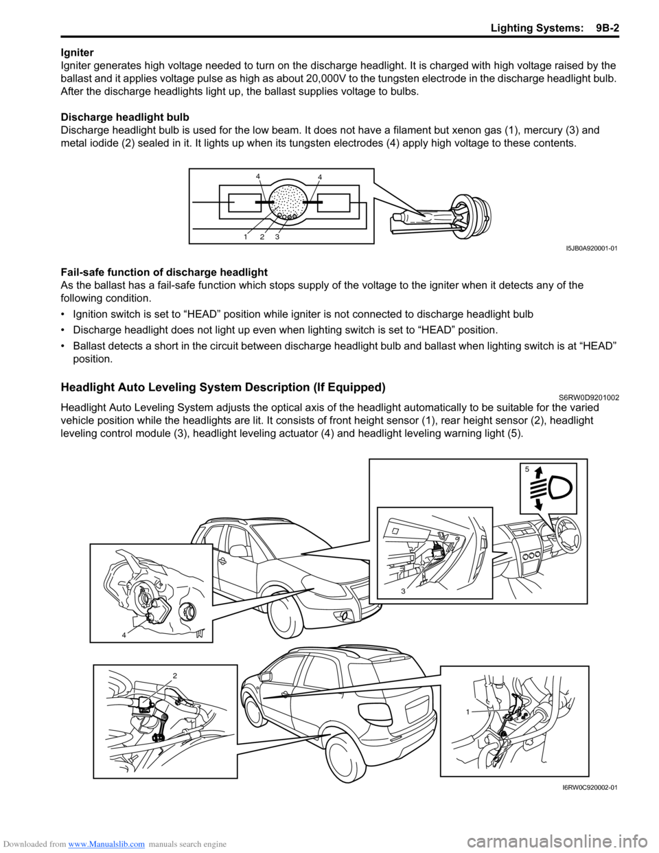
Discharge headlight bulb is used for the low beam. It does not have a filament but xenon gas (1), mercury (3) and
metal iodide (2) sealed in it. It lights up when its tungsten electrodes (4) apply high voltage to these contents.
Fail-safe function of discharge headlight
As the ballast has a fail-safe function which stops supply of the voltage to the igniter when it detects any of the
following condition.
• Ignition switch is set to “HEAD” position while igniter is not connected to discharge headlight bulb
• Discharge headlight does not light up even when lighting switch is set to “HEAD” position.
• Ballast detects a short in the circuit between discharge headlight bulb and ballast when lighting switch is at “HEAD”
position.
Headlight Auto Leveling System Description (If Equipped)S6RW0D9201002
Headlight Auto Leveling System adjusts the optical axis of the headlight automatically to be suitable for the varied
vehicle position while the headlights are lit. It consists of front height sensor (1), rear height sensor (2), headlight
leveling control module (3), headlight leveling actuator (4) and headlight leveling warning light (5).
123
44
I5JB0A920001-01
4
3
5
1
2
I6RW0C920002-01
Page 1322 of 1556
Downloaded from www.Manualslib.com manuals search engine 9B-3 Lighting Systems:
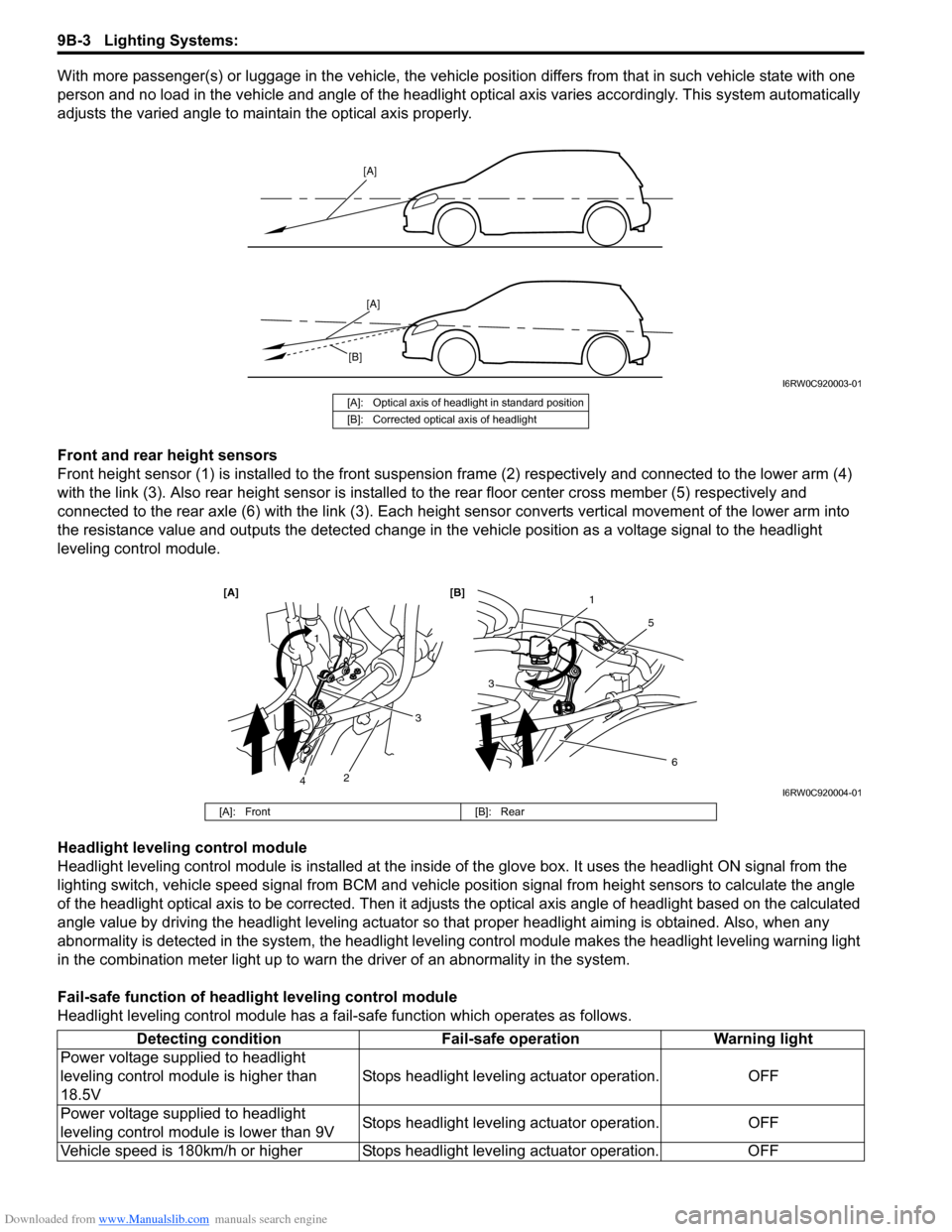
With more passenger(s) or luggage in the vehicle, the vehicle position differs from that in such vehicle state with one
person and no load in the vehicle and angle of the headlight optical axis varies accordingly. This system automatically
adjusts the varied angle to maintain the optical axis properly.
Front and rear height sensors
Front height sensor (1) is installed to the front suspension frame (2) respectively and connected to the lower arm (4)
with the link (3). Also rear height sensor is installed to the rear floor center cross member (5) respectively and
connected to the rear axle (6) with the link (3). Each height sensor converts vertical movement of the lower arm into
the resistance value and outputs the detected change in the vehicle position as a voltage signal to the headlight
leveling control module.
Headlight leveling control module
Headlight leveling control module is installed at the inside of the glove box. It uses the headlight ON signal from the
lighting switch, vehicle speed signal from BCM and vehicle position signal from height sensors to calculate the angle
of the headlight optical axis to be corrected. Then it adjusts the optical axis angle of headlight based on the calculated
angle value by driving the headlight leveling actuator so that proper headlight aiming is obtained. Also, when any
abnormality is detected in the system, the headlight leveling control module makes the headlight leveling warning light
in the combination meter light up to warn the driver of an abnormality in the system.
Fail-safe function of headlight leveling control module
Headlight leveling control module has a fail-safe function which operates as follows.
[A]
[A]
[B]
I6RW0C920003-01
[A]: Optical axis of headlight in standard position
[B]: Corrected optical axis of headlight
1
5
[A] [B]
6
3
1
2
3
4I6RW0C920004-01
[A]: Front [B]: Rear
Detecting condition Fail-safe operation Warning light
Power voltage supplied to headlight
leveling control module is higher than
18.5VStops headlight leveling actuator operation. OFF
Power voltage supplied to headlight
leveling control module is lower than 9VStops headlight leveling actuator operation. OFF
Vehicle speed is 180km/h or higher Stops headlight leveling actuator operation. OFF
Page 1324 of 1556

Downloaded from www.Manualslib.com manuals search engine 9B-5 Lighting Systems:
Schematic and Routing Diagram
Headlight Auto Leveling System Wiring Circuit DiagramS6RW0D9202001
G14-12G14-19G14-21
G14-10
G14-23
+B
5V
5V
GRN/YEL
GRY/RED
BLK
G14-112V
BRNLT BLUGRY
RED/BLK
3
G14-13G14-20G14-22
5V
PNKBLUYEL/GRN2
45
9
10 11 1
5V
5V
12V
G14-16
G14-3
PPL
GRN/ORN
5V
G14-5YEL
G14-17GRN
G14-11
G14-24
ORN
WHT6 12VG14-18LT GRN
7
8
G14-6
G14-9
RED/WHT
G14
10 11 12 13 16 17 18 19 205 6 9
21 22 23 24
[A]
I6RW0C920007-01
[A]: Headlight leveling control module connector
(viewed from harness side)4. BCM 8. Headlight leveling warning light
1. Headlight leveling control module 5. Right headlight leveling actuator 9. Ignition switch
2. Front height sensor 6. Left headlight leveling actuator 10. Lighting switch
3. Rear height sensor 7. Combination meter 11. Diagnosis connector
Page 1326 of 1556
Downloaded from www.Manualslib.com manuals search engine 9B-7 Lighting Systems:
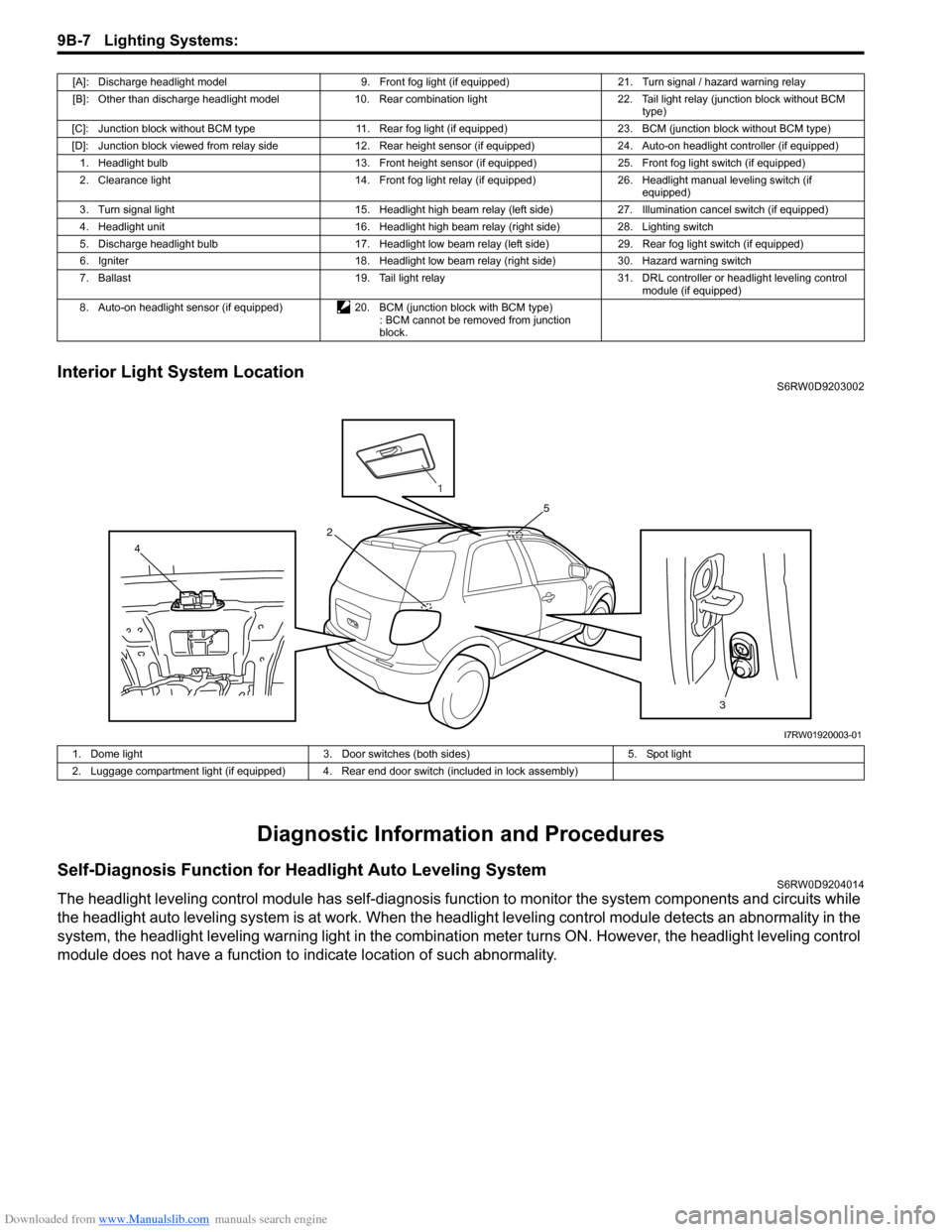
Interior Light System LocationS6RW0D9203002
Diagnostic Information and Procedures
Self-Diagnosis Function for Headlight Auto Leveling SystemS6RW0D9204014
The headlight leveling control module has self-diagnosis function to monitor the system components and circuits while
the headlight auto leveling system is at work. When the headlight leveling control module detects an abnormality in the
system, the headlight leveling warning light in the combination meter turns ON. However, the headlight leveling control
module does not have a function to indicate location of such abnormality.
[A]: Discharge headlight model 9. Front fog light (if equipped) 21. Turn signal / hazard warning relay
[B]: Other than discharge headlight model 10. Rear combination light 22. Tail light relay (junction block without BCM
type)
[C]: Junction block without BCM type 11. Rear fog light (if equipped) 23. BCM (junction block without BCM type)
[D]: Junction block viewed from relay side 12. Rear height sensor (if equipped) 24. Auto-on headlight controller (if equipped)
1. Headlight bulb 13. Front height sensor (if equipped) 25. Front fog light switch (if equipped)
2. Clearance light 14. Front fog light relay (if equipped) 26. Headlight manual leveling switch (if
equipped)
3. Turn signal light 15. Headlight high beam relay (left side) 27. Illumination cancel switch (if equipped)
4. Headlight unit 16. Headlight high beam relay (right side) 28. Lighting switch
5. Discharge headlight bulb 17. Headlight low beam relay (left side) 29. Rear fog light switch (if equipped)
6. Igniter 18. Headlight low beam relay (right side) 30. Hazard warning switch
7. Ballast 19. Tail light relay 31. DRL controller or headlight leveling control
module (if equipped)
8. Auto-on headlight sensor (if equipped) 20. BCM (junction block with BCM type)
: BCM cannot be removed from junction
block.
3 4
5
2
1
I7RW01920003-01
1. Dome light 3. Door switches (both sides) 5. Spot light
2. Luggage compartment light (if equipped) 4. Rear end door switch (included in lock assembly)
Page 1327 of 1556
Downloaded from www.Manualslib.com manuals search engine Lighting Systems: 9B-8
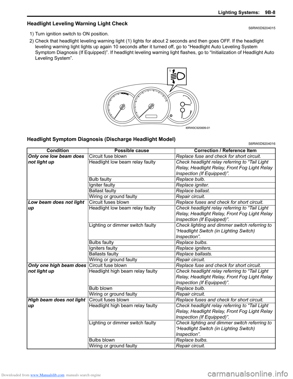
Headlight Leveling Warning Light CheckS6RW0D9204015
1) Turn ignition switch to ON position.
2) Check that headlight leveling warning light (1) lights for about 2 seconds and then goes OFF. If the headlight
leveling warning light lights up again 10 seconds after it turned off, go to “Headlight Auto Leveling System
Symptom Diagnosis (If Equipped)”. If headlight leveling warning light flashes, go to “Initialization of Headlight Auto
Leveling System”.
Headlight Symptom Diagnosis (Discharge Headlight Model)S6RW0D9204016
1
I6RW0C920009-01
Condition Possible cause Correction / Reference Item
Only one low beam does
not light upCircuit fuse blownReplace fuse and check for short circuit.
Headlight low beam relay faultyCheck headlight relay referring to “Tail Light
Relay, Headlight Relay, Front Fog Light Relay
Inspection (If Equipped)”.
Bulb faultyReplace bulb.
Igniter faultyReplace igniter.
Ballast faultyReplace ballast.
Wiring or ground faultyRepair circuit.
Low beam does not light
upCircuit fuses blownReplace fuses and check for short circuit.
Headlight low beam relay faultyCheck headlight relay referring to “Tail Light
Relay, Headlight Relay, Front Fog Light Relay
Inspection (If Equipped)”.
Lighting or dimmer switch faultyCheck lighting and dimmer switch referring to
“Headlight Switch (in Lighting Switch)
Inspection”.
Bulbs faultyReplace bulbs.
Igniters faultyReplace igniters.
Ballasts faultyReplace ballasts.
Wiring or ground faultyRepair circuit.
Only one high beam does
not light upCircuit fuse blownReplace fuse and check for short circuit.
Headlight high beam relay faultyCheck headlight relay referring to “Tail Light
Relay, Headlight Relay, Front Fog Light Relay
Inspection (If Equipped)”.
Bulb blownReplace bulb.
Wiring or ground faultyRepair circuit.
High beam does not light
upCircuit fuses blownReplace fuses and check for short circuit.
Headlight high beam relay faultyCheck headlight relay referring to “Tail Light
Relay, Headlight Relay, Front Fog Light Relay
Inspection (If Equipped)”.
Lighting or dimmer switch faultyCheck lighting and dimmer switch referring to
“Headlight Switch (in Lighting Switch)
Inspection”.
Bulbs blownReplace bulbs.
Wiring or ground faultyRepair circuit.
Page 1328 of 1556
Downloaded from www.Manualslib.com manuals search engine 9B-9 Lighting Systems:
Headlight Symptom diagnosis (Other than Discharge Headlight Model)S6RW0D9204017
Auto-On Headlight System Symptom Diagnosis (If Equipped)S6RW0D9204018
Condition Possible cause Correction / Reference Item
Only one low beam does
not light upCircuit fuse blownReplace fuse and check for short circuit.
Bulb blownReplace bulb.
Headlight low beam relay faulty (if
equipped)Check headlight relay referring to “Tail Light
Relay, Headlight Relay, Front Fog Light Relay
Inspection (If Equipped)”.
Wiring or ground faultyRepair circuit.
Low beam does not light
upCircuit fuse blownReplace fuses and check for short circuit.
Headlight low beam relay faulty (if
equipped)Check headlight relay referring to “Tail Light
Relay, Headlight Relay, Front Fog Light Relay
Inspection (If Equipped)”.
Lighting or dimmer switch faultyCheck lighting and dimmer switch referring to
“Headlight Switch (in Lighting Switch)
Inspection”.
Bulbs blownReplace bulbs.
Wiring or ground faultyRepair circuit.
DRL controller faulty (if equipped)Check system referring to “Inspection of DRL
Controller and Its Circuits (If Equipped)”.
Only one high beam does
not light upCircuit fuse blownReplace fuse and check for short circuit.
Bulb blownReplace bulb.
Headlight high beam relay faulty (if
equipped)Check headlight relay referring to “Tail Light
Relay, Headlight Relay, Front Fog Light Relay
Inspection (If Equipped)”.
Wiring or ground faultyRepair circuit.
High beam does not light
upCircuit fuse blownReplace fuses and check for short circuit.
Headlight high beam relay faulty (if
equipped)Check headlight relay referring to “Tail Light
Relay, Headlight Relay, Front Fog Light Relay
Inspection (If Equipped)”.
Lighting or dimmer switch faultyCheck lighting and dimmer switch referring to
“Headlight Switch (in Lighting Switch)
Inspection”.
Bulbs blownReplace bulbs.
Wiring or ground faultyRepair circuit.
Condition Possible cause Correction / Reference Item
Headlights are not turned
ON or OFF automatically
even after darkened or
lightenedCircuit fuse blownReplace fuse and check for short circuit.
Lighting or dimmer switch faultyCheck lighting and dimmer switch referring to
“Headlight Switch (in Lighting Switch)
Inspection”.
Auto-on headlight sensor faultyCheck auto-on headlight sensor referring to
“Auto-On Headlight Sensor Inspection (If
Equipped)”.
Wiring or ground faultyRepair circuit.
Auto-on headlight controller faultyCheck auto-on headlight controller for function
referring to “Inspection of Auto-On Headlight
Controller and Its Circuit (If Equipped)”.
Page 1330 of 1556
Downloaded from www.Manualslib.com manuals search engine 9B-11 Lighting Systems:
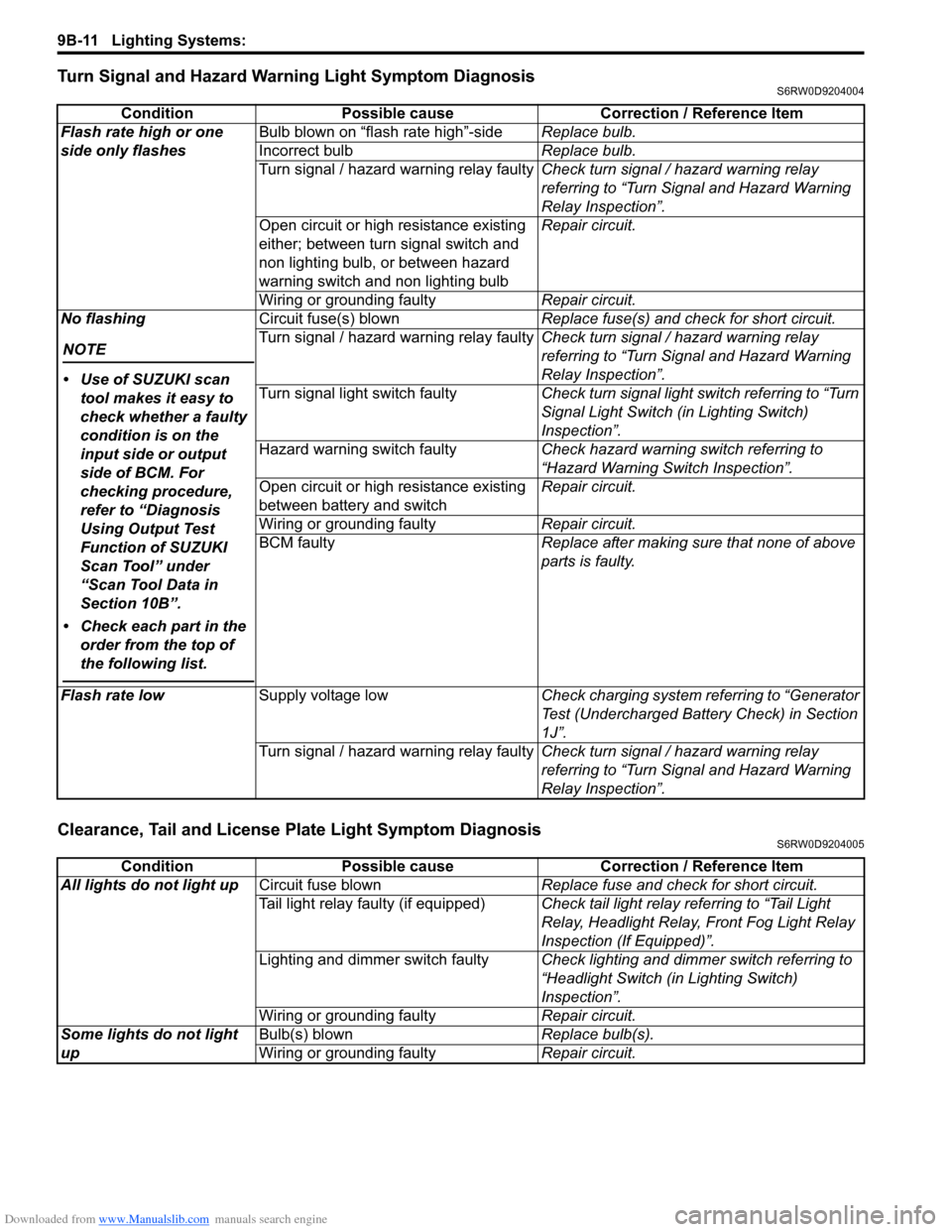
Turn Signal and Hazard Warning Light Symptom DiagnosisS6RW0D9204004
Clearance, Tail and License Plate Light Symptom DiagnosisS6RW0D9204005
Condition Possible cause Correction / Reference Item
Flash rate high or one
side only flashesBulb blown on “flash rate high”-sideReplace bulb.
Incorrect bulbReplace bulb.
Turn signal / hazard warning relay faultyCheck turn signal / hazard warning relay
referring to “Turn Signal and Hazard Warning
Relay Inspection”.
Open circuit or high resistance existing
either; between turn signal switch and
non lighting bulb, or between hazard
warning switch and non lighting bulbRepair circuit.
Wiring or grounding faultyRepair circuit.
No flashing
NOTE
• Use of SUZUKI scan
tool makes it easy to
check whether a faulty
condition is on the
input side or output
side of BCM. For
checking procedure,
refer to “Diagnosis
Using Output Test
Function of SUZUKI
Scan Tool” under
“Scan Tool Data in
Section 10B”.
• Check each part in the
order from the top of
the following list.
Circuit fuse(s) blownReplace fuse(s) and check for short circuit.
Turn signal / hazard warning relay faultyCheck turn signal / hazard warning relay
referring to “Turn Signal and Hazard Warning
Relay Inspection”.
Turn signal light switch faultyCheck turn signal light switch referring to “Turn
Signal Light Switch (in Lighting Switch)
Inspection”.
Hazard warning switch faultyCheck hazard warning switch referring to
“Hazard Warning Switch Inspection”.
Open circuit or high resistance existing
between battery and switchRepair circuit.
Wiring or grounding faultyRepair circuit.
BCM faultyReplace after making sure that none of above
parts is faulty.
Flash rate lowSupply voltage lowCheck charging system referring to “Generator
Test (Undercharged Battery Check) in Section
1J”.
Turn signal / hazard warning relay faultyCheck turn signal / hazard warning relay
referring to “Turn Signal and Hazard Warning
Relay Inspection”.
Condition Possible cause Correction / Reference Item
All lights do not light upCircuit fuse blownReplace fuse and check for short circuit.
Tail light relay faulty (if equipped)Check tail light relay referring to “Tail Light
Relay, Headlight Relay, Front Fog Light Relay
Inspection (If Equipped)”.
Lighting and dimmer switch faultyCheck lighting and dimmer switch referring to
“Headlight Switch (in Lighting Switch)
Inspection”.
Wiring or grounding faultyRepair circuit.
Some lights do not light
upBulb(s) blownReplace bulb(s).
Wiring or grounding faultyRepair circuit.