fuse diagram SUZUKI SX4 2006 1.G Service Repair Manual
[x] Cancel search | Manufacturer: SUZUKI, Model Year: 2006, Model line: SX4, Model: SUZUKI SX4 2006 1.GPages: 1556, PDF Size: 37.31 MB
Page 902 of 1556
Downloaded from www.Manualslib.com manuals search engine 6C-22 Power Assisted Steering System:
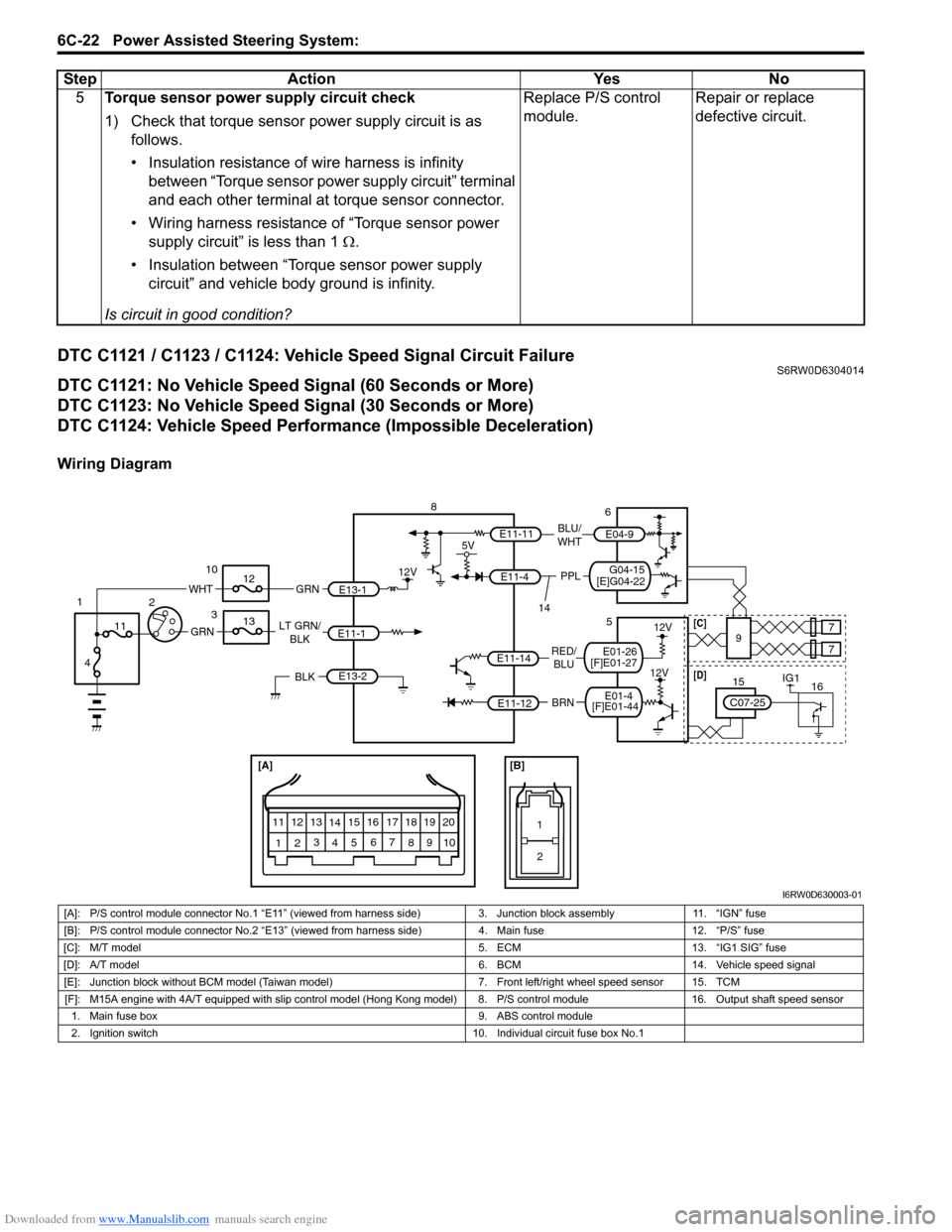
DTC C1121 / C1123 / C1124: Vehicle Speed Signal Circuit FailureS6RW0D6304014
DTC C1121: No Vehicle Speed Signal (60 Seconds or More)
DTC C1123: No Vehicle Speed Signal (30 Seconds or More)
DTC C1124: Vehicle Speed Performance (Impossible Deceleration)
Wiring Diagram5Torque sensor power supply circuit check
1) Check that torque sensor power supply circuit is as
follows.
• Insulation resistance of wire harness is infinity
between “Torque sensor power supply circuit” terminal
and each other terminal at torque sensor connector.
• Wiring harness resistance of “Torque sensor power
supply circuit” is less than 1 Ω.
• Insulation between “Torque sensor power supply
circuit” and vehicle body ground is infinity.
Is circuit in good condition?Replace P/S control
module.Repair or replace
defective circuit. Step Action Yes No
[A]
123
4567
8
9 11
10 12 13
141516
17 18 1920
1
2
[B]
BRN RED/
BLU LT GRN/
BLK
E11-1
E11-14
E11-12
E13-1 GRN
GRN
WHT
8
3 10
12
13
11
4 1
2
12V
E13-2BLK
12V
12V
9 5
77
E11-11
G04-15
[E]G04-22
5V
PPL
E11-4
BLU/
WHTE04-9
6
14
IG11615
C07-25
[D][C]
[F]E01-44E01-4
[F]E01-27E01-26
I6RW0D630003-01
[A]: P/S control module connector No.1 “E11” (viewed from harness side) 3. Junction block assembly 11. “IGN” fuse
[B]: P/S control module connector No.2 “E13” (viewed from harness side) 4. Main fuse 12. “P/S” fuse
[C]: M/T model 5. ECM 13. “IG1 SIG” fuse
[D]: A/T model 6. BCM 14. Vehicle speed signal
[E]: Junction block without BCM model (Taiwan model) 7. Front left/right wheel speed sensor 15. TCM
[F]: M15A engine with 4A/T equipped with slip control model (Hong Kong model) 8. P/S control module 16. Output shaft speed sensor
1. Main fuse box 9. ABS control module
2. Ignition switch 10. Individual circuit fuse box No.1
Page 904 of 1556
Downloaded from www.Manualslib.com manuals search engine 6C-24 Power Assisted Steering System:
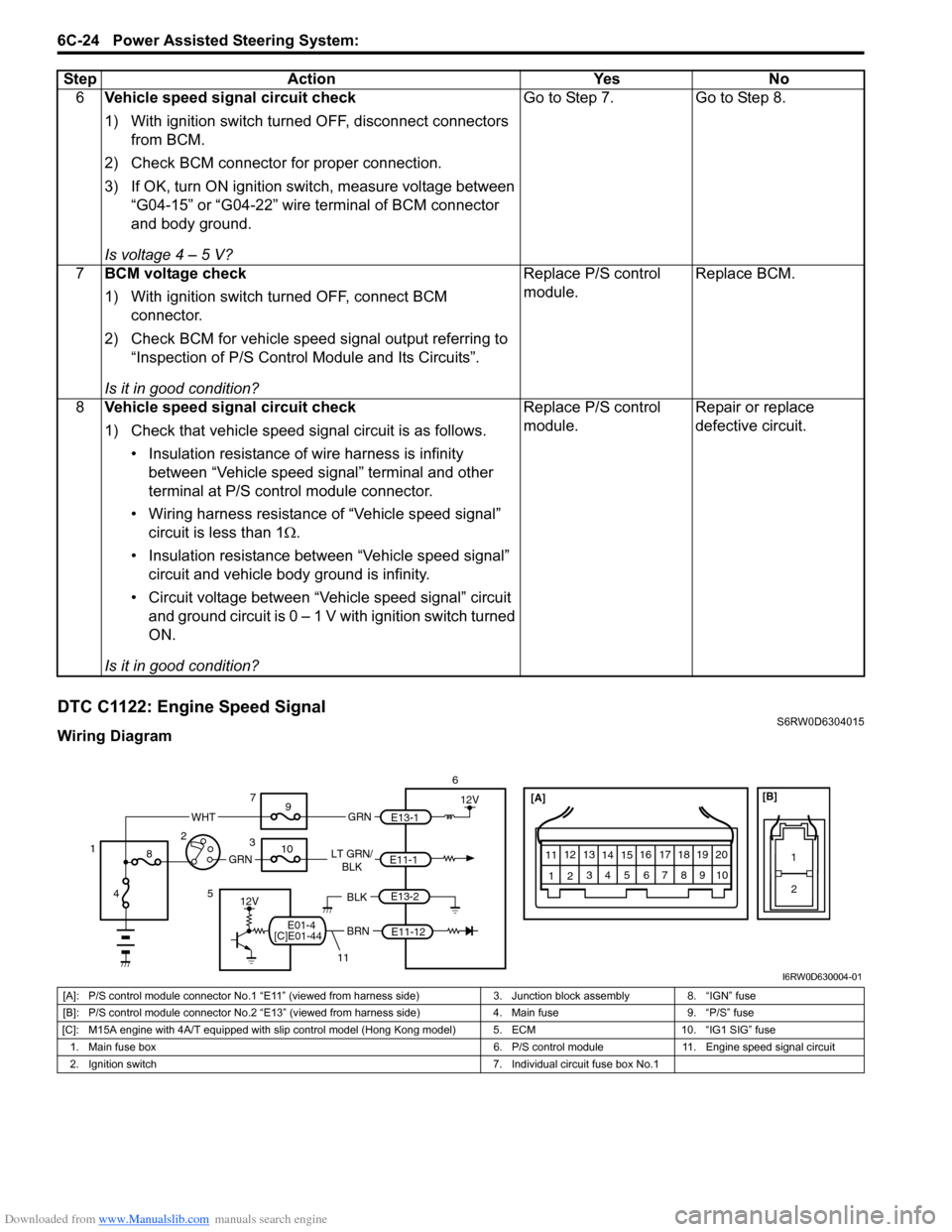
DTC C1122: Engine Speed SignalS6RW0D6304015
Wiring Diagram6Vehicle speed signal circuit check
1) With ignition switch turned OFF, disconnect connectors
from BCM.
2) Check BCM connector for proper connection.
3) If OK, turn ON ignition switch, measure voltage between
“G04-15” or “G04-22” wire terminal of BCM connector
and body ground.
Is voltage 4 – 5 V?Go to Step 7. Go to Step 8.
7BCM voltage check
1) With ignition switch turned OFF, connect BCM
connector.
2) Check BCM for vehicle speed signal output referring to
“Inspection of P/S Control Module and Its Circuits”.
Is it in good condition?Replace P/S control
module.Replace BCM.
8Vehicle speed signal circuit check
1) Check that vehicle speed signal circuit is as follows.
• Insulation resistance of wire harness is infinity
between “Vehicle speed signal” terminal and other
terminal at P/S control module connector.
• Wiring harness resistance of “Vehicle speed signal”
circuit is less than 1Ω.
• Insulation resistance between “Vehicle speed signal”
circuit and vehicle body ground is infinity.
• Circuit voltage between “Vehicle speed signal” circuit
and ground circuit is 0 – 1 V with ignition switch turned
ON.
Is it in good condition?Replace P/S control
module.Repair or replace
defective circuit. Step Action Yes No
[A]
123
4567
8
9 11
10 12 13
141516
17 18 1920
1
2
[B]
BRN LT GRN/
BLK
E11-1
E11-12
E13-1 GRN
GRN
WHT
6
37
9
10
8
4 12
12V
E13-2BLK12V5
11
[C]E01-44E01-4
I6RW0D630004-01
[A]: P/S control module connector No.1 “E11” (viewed from harness side) 3. Junction block assembly 8. “IGN” fuse
[B]: P/S control module connector No.2 “E13” (viewed from harness side) 4. Main fuse 9. “P/S” fuse
[C]: M15A engine with 4A/T equipped with slip control model (Hong Kong model) 5. ECM 10. “IG1 SIG” fuse
1. Main fuse box 6. P/S control module 11. Engine speed signal circuit
2. Ignition switch 7. Individual circuit fuse box No.1
Page 906 of 1556
Downloaded from www.Manualslib.com manuals search engine 6C-26 Power Assisted Steering System:
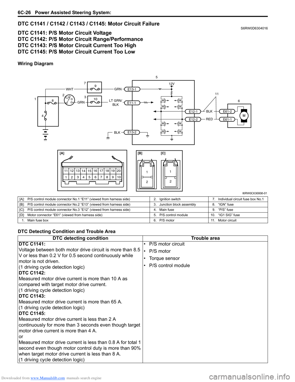
DTC C1141 / C1142 / C1143 / C1145: Motor Circuit FailureS6RW0D6304016
DTC C1141: P/S Motor Circuit Voltage
DTC C1142: P/S Motor Circuit Range/Performance
DTC C1143: P/S Motor Circuit Current Too High
DTC C1145: P/S Motor Circuit Current Too Low
Wiring Diagram
DTC Detecting Condition and Trouble Area
[A]
123
4567
8
9 11
10 12 13
141516
17 18 1920
1
2
[B]
1
2
[C]
LT GRN/
BLK
BLK
RED
E11-1
E12-1
E12-2 E13-1 GRNGRN
WHT
5
6 3 7
9
10
8
4 12
12V
E13-2BLK
E61-2
E61-1
11
I6RW0C630008-01
[A]: P/S control module connector No.1 “E11” (viewed from harness side) 2. Ignition switch 7. Individual circuit fuse box No.1
[B]: P/S control module connector No.2 “E13” (viewed from harness side) 3. Junction block assembly 8. “IGN” fuse
[C]: P/S control module connector No.3 “E12” (viewed from harness side) 4. Main fuse 9. “P/S” fuse
[D]: Motor connector “E61” (viewed from harness side) 5. P/S control module 10. “IG1 SIG” fuse
1. Main fuse box 6. P/S motor 11. Motor circuit
DTC detecting condition Trouble area
DTC C1141:
Voltage between both motor drive circuit is more than 8.5
V or less than 0.2 V for 0.5 second continuously while
motor is not driven.
(1 driving cycle detection logic)
DTC C1142:
Measured motor drive current is more than 10 A as
compared with target motor drive current.
(1 driving cycle detection logic)
DTC C1143:
Measured motor drive current is more than 65 A.
(1 driving cycle detection logic)
DTC C1145:
Measured motor drive current is less than 2 A
continuously for more than 3 seconds even though target
motor drive current is more than 4 A.
or
Measured motor drive current is less than 0.8 A for total 1
second even though motor control duty is more than 90%
when target motor drive current is less than 8 A.
(1 driving cycle detection logic)• P/S motor circuit
• P/S motor
• Torque sensor
• P/S control module
Page 907 of 1556
Downloaded from www.Manualslib.com manuals search engine Power Assisted Steering System: 6C-27
DTC Troubleshooting
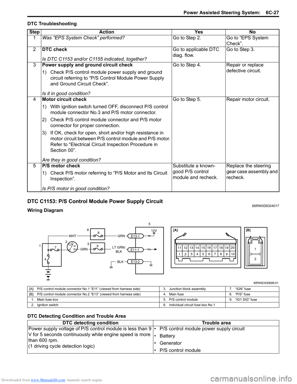
DTC C1153: P/S Control Module Power Supply CircuitS6RW0D6304017
Wiring Diagram
DTC Detecting Condition and Trouble AreaStep Action Yes No
1Was “EPS System Check” performed?Go to Step 2. Go to “EPS System
Check”.
2DTC check
Is DTC C1153 and/or C1155 indicated, together?Go to applicable DTC
diag. flow.Go to Step 3.
3Power supply and ground circuit check
1) Check P/S control module power supply and ground
circuit referring to “P/S Control Module Power Supply
and Ground Circuit Check”.
Is it in good condition?Go to Step 4. Repair or replace
defective circuit.
4Motor circuit check
1) With ignition switch turned OFF, disconnect P/S control
module connector No.3 and P/S motor connector.
2) Check P/S control module connector and P/S motor
connector for proper connection.
3) If OK, check for open, short and/or high resistance in
motor circuit between P/S control module and P/S motor.
Refer to “Electrical Circuit Inspection Procedure in
Section 00”.
Are they in good condition?Go to Step 5. Repair motor circuit.
5P/S motor check
1) Check P/S motor referring to “P/S Motor and Its Circuit
Inspection”.
Is P/S motor in good condition?Substitute a known-
good P/S control
module and recheck.Replace the steering
gear case assembly and
recheck.
[A]
123
4567
8
9 11
10 12 13
141516
17 18 1920
1
2
[B]
LT GRN/
BLKE11-1E13-1 GRNGRN
WHT
5
3 6
8
9
7
4 12
12V
E13-2BLK
I6RW0C630009-01
[A]: P/S control module connector No.1 “E11” (viewed from harness side) 3. Junction block assembly 7. “IGN” fuse
[B]: P/S control module connector No.2 “E13” (viewed from harness side) 4. Main fuse 8. “P/S” fuse
1. Main fuse box 5. P/S control module 9. “IG1 SIG” fuse
2. Ignition switch 6. Individual circuit fuse box No.1
DTC detecting condition Trouble area
Power supply voltage of P/S control module is less than 9
V for 5 seconds continuously while engine speed is more
than 600 rpm.
(1 driving cycle detection logic)• P/S control module power supply circuit
• Battery
• Generator
• P/S control module
Page 908 of 1556
Downloaded from www.Manualslib.com manuals search engine 6C-28 Power Assisted Steering System:
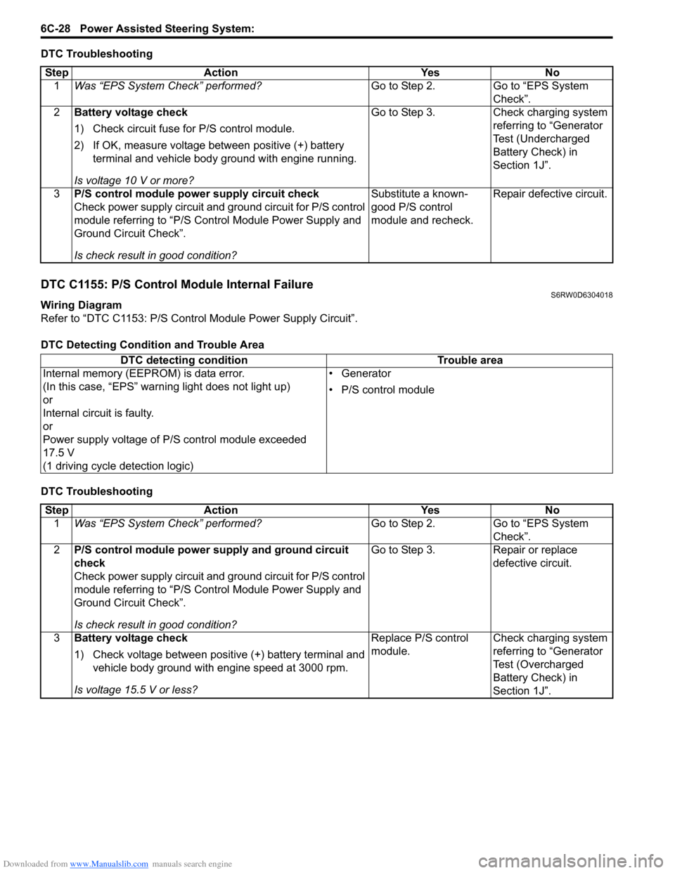
DTC Troubleshooting
DTC C1155: P/S Control Module Internal FailureS6RW0D6304018
Wiring Diagram
Refer to “DTC C1153: P/S Control Module Power Supply Circuit”.
DTC Detecting Condition and Trouble Area
DTC TroubleshootingStep Action Yes No
1Was “EPS System Check” performed?Go to Step 2. Go to “EPS System
Check”.
2Battery voltage check
1) Check circuit fuse for P/S control module.
2) If OK, measure voltage between positive (+) battery
terminal and vehicle body ground with engine running.
Is voltage 10 V or more?Go to Step 3. Check charging system
referring to “Generator
Test (Undercharged
Battery Check) in
Section 1J”.
3P/S control module power supply circuit check
Check power supply circuit and ground circuit for P/S control
module referring to “P/S Control Module Power Supply and
Ground Circuit Check”.
Is check result in good condition?Substitute a known-
good P/S control
module and recheck.Repair defective circuit.
DTC detecting condition Trouble area
Internal memory (EEPROM) is data error.
(In this case, “EPS” warning light does not light up)
or
Internal circuit is faulty.
or
Power supply voltage of P/S control module exceeded
17.5 V
(1 driving cycle detection logic)• Generator
• P/S control module
Step Action Yes No
1Was “EPS System Check” performed?Go to Step 2. Go to “EPS System
Check”.
2P/S control module power supply and ground circuit
check
Check power supply circuit and ground circuit for P/S control
module referring to “P/S Control Module Power Supply and
Ground Circuit Check”.
Is check result in good condition?Go to Step 3. Repair or replace
defective circuit.
3Battery voltage check
1) Check voltage between positive (+) battery terminal and
vehicle body ground with engine speed at 3000 rpm.
Is voltage 15.5 V or less?Replace P/S control
module.Check charging system
referring to “Generator
Test (Overcharged
Battery Check) in
Section 1J”.
Page 909 of 1556

Downloaded from www.Manualslib.com manuals search engine Power Assisted Steering System: 6C-29
P/S Control Module Power Supply and Ground Circuit CheckS6RW0D6304019
Wiring Diagram
Refer to “DTC C1153: P/S Control Module Power Supply Circuit”.
DTC Troubleshooting
Step Action Yes No
1Circuit fuse check
1) Disconnect P/S control module connector with ignition
switch turned OFF.
2) Check for proper connection to P/S control module
connector at “E13-1”, “E13-2” and “E11-1” terminals.
3) If OK, check “P/S” fuse and “IG1 SIG” fuse for blowing.
Are “P/S” fuse and “IG1 SIG” fuse in good condition?Go to Step 2. Replace fuse (s) and
check for short in
circuits connected to
fuse(s).
2Power supply circuit check
1) Measure voltage between “E13-1” terminal of P/S
control module connector and body ground.
Is voltage 10 – 14 V?Go to Step 3. “GRN” or “WHT” wire is
open circuit.
3Ignition signal check
1) Turn ignition switch to ON position.
2) Measure voltage between “E11-1” terminal of P/S control
module connector and body ground.
Is voltage 10 – 14 V?Go to Step 4. “LT GRN / BLK” or
“GRN” wire is open
circuit.
4P/S control module ground circuit check
1) Turn ignition switch to OFF position.
2) Disconnect connectors from P/S control module.
3) Measure resistance between “E13-2” terminals of P/S
control module connector and body ground.
Is resistance 1
Ω or less?Go to Step 5. “BLK” wire is open or
high resistance circuit.
5P/S control module ground circuit check
1) Connect connectors to P/S control module.
2) Start engine.
3) Measure voltage between “E13-2” terminals of P/S
control module connector and body ground when
steering wheel fully turned to left or right.
Is voltage 0.3 V or less?P/S Control Module
Power Supply and
Ground Circuit is in
good condition.“BLK” wire is high
resistance circuit.
Page 930 of 1556
Downloaded from www.Manualslib.com manuals search engine 7A-2 Heater and Ventilation:
Schematic and Routing Diagram
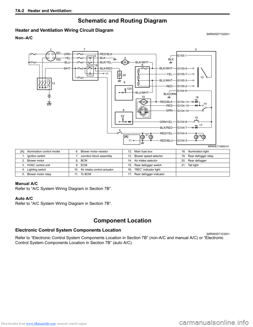
Heater and Ventilation Wiring Circuit DiagramS6RW0D7102001
Non–A/C
Manual A/C
Refer to “A/C System Wiring Diagram in Section 7B”.
Auto A/C
Refer to “A/C System Wiring Diagram in Section 7B”.
Component Location
Electronic Control System Components LocationS6RW0D7103001
Refer to “Electronic Control System Components Location in Section 7B” (non-A/C and manual A/C) or “Electronic
Control System Components Location in Section 7B” (auto A/C).
5V
BLK
RED/BLK3
5 72
G154-3
G154-4
G154-7
G154-8
G154-10
G154-13
G155-2
G155-3
G155-7
G155-6
G155-1
G154-9
G154-14
BLK/WHT
YEL
BLU/WHT
RED
RED/BLKRED
GRN
GRN/YEL
RED/YEL
RED/BLU
BLK/ORN
46
8
BLU
YELGRN
WHT
13
1514
[A]21
BLK/RED
12V
BLK/YELBLK/WHTM
BLK
1IG1
IG2
12
BLK/RED
M 10
11
11
BLU/WHT 19
16
17
18 9 20
I6RW0C710003-01
[A]: Illumination control model 6. Blower motor resistor 12. Main fuse box 18. Illumination light
1. Ignition switch 7. Junction block assembly 13. Blower speed selector 19. Rear defogger relay
2. Blower motor 8. BCM 14. Air intake selector 20. Rear defogger
3. HVAC control unit 9. ECM 15. Rear defogger switch 21. Tail light
4. Lighting switch 10. Air intake control actuator 16. “REC” indicator light
5. Blower motor relay 11. To BCM 17. Rear defogger indicator
Page 945 of 1556
![SUZUKI SX4 2006 1.G Service Repair Manual Downloaded from www.Manualslib.com manuals search engine Air Conditioning System: Manual Type 7B-5
A/C System Wiring DiagramS6RW0D7212002
[A]
7
WHT
GRN5YELBLK
3
G154-3
G154-4
G154-7
G154-8
G154-10
G15 SUZUKI SX4 2006 1.G Service Repair Manual Downloaded from www.Manualslib.com manuals search engine Air Conditioning System: Manual Type 7B-5
A/C System Wiring DiagramS6RW0D7212002
[A]
7
WHT
GRN5YELBLK
3
G154-3
G154-4
G154-7
G154-8
G154-10
G15](/img/20/7612/w960_7612-944.png)
Downloaded from www.Manualslib.com manuals search engine Air Conditioning System: Manual Type 7B-5
A/C System Wiring DiagramS6RW0D7212002
[A]
7
WHT
GRN5YELBLK
3
G154-3
G154-4
G154-7
G154-8
G154-10
G154-13
G154-5
G154-6
G155-5
G155-2
G155-3
G155-7
G155-6
G155-1
G154-9
G154-14
BLK/WHT
YEL
BLU/WHT
RED
BRN
GRN/WHT
RED/BLK
RED
GRN
GRN/YEL
RED/YEL
RED/BLU
20
21
23 22
BLK/RED
6 2
MBLK/WHTBLK/YEL
M
11
4RED/YEL 1
E01-49
12
E01-16
GRY 13
12V
BLU/WHTE01-3510
E01-48
18
19RED/BLK
BLK/RED
BLK/RED
BRN/WHTE01-60
E01-1
E01-29BLK/WHT
M
BLU/YELBLK/YEL
5V5V 5V
WHT/BLK
9
ORN
14E01-36
C01-12C01-14GRY/REDRED/BLU
E01-41
RED/BLK
RED
WHT
8
BLK
BLK/ORN
BLU IG1
IG2
5V
17
28
29
31
2726 2524
16
16
30
34
33E01-4 E01-19WHTRED
C01-50C01-49WHTRED
32
LT GRN
C01-57
C01-2415
GRY/BLU5V
I6RW0C721002-01
[A]: Illumination control model 9. A/C refrigerant pressure
sensor18. Condenser cooling fan relay 27. Illumination light
1. Ignition switch 10. ECM 19. Condenser cooling fan motor 28. Rear defogger relay
2. Blower motor 11. Air intake control actuator 20. Blower speed selector 29. Rear defogger
3. HVAC control unit 12. Compressor relay 21. A/C switch 30. Main relay
4. Lighting switch 13. Compressor 22. Air intake selector 31. Tail light
5. Blower motor relay 14. Evaporator temperature
sensor23. Rear defogger switch 32. TCM
6. Blower motor resistor 15. ECT sensor 24. “A/C” indicator light 33. To other control module and DLC
7. Junction block assembly 16. To BCM 25. “REC” indicator light 34. ABS control module
8. BCM 17. Main fuse box 26. Rear defogger indicator
Page 997 of 1556
Downloaded from www.Manualslib.com manuals search engine Air Conditioning System: Automatic Type 7B-57
SUN LOAD (W/m2): This parameter indicates the
amount of sunlight detected by sunload sensor.
MODE CONT SWITCH (Air flow selector position,
AUTO, FACE, B/L, FOOT, D/F, DEF): This
parameter indicates the selected position of air flow
selector.
FAN CONT SWITCH (Blower speed selector, AUTO,
OFF, 1st – 8th): This parameter indicates the
selected position of blower speed selector.
FAN DESIRE VOLT (Fan desired voltage, V): This
parameter indicates the consumption voltage of
blower motor.
AIR MIX POS SENSOR (Temperature control
actuator position sensor, V): This parameter
indicates the input signal from position sensor in
temperature control actuator.
MODE POS SENSOR (Air flow control actuator
position sensor, V): This parameter indicates the
input signal from position sensor in air flow control
actuator.
A/C CONT SIG (A/C control signal, ON, OFF): This
parameter indicates the state of A/C switch.BLOWER LOAD SIG (Blower fan load signal, ON,
OFF): ON: Position of blower speed selector is 1st
position or more.
OFF: Position of blower speed selector is OFF
position.
AIR INTAKE MODE (Air intake selector position,
AUTO, FRE, REC): This parameter indicates the
selected position of air intake selector.
REFRIGERANT PRESSURE (A/C refrigerant absolute
pressure, kPa): This parameter indicates the A/C
refrigerant absolute pressure calculated by ECM
A/C COMP CLUCH (A/C compressor magnet clutch,
ON, OFF): This parameter indicates the state of the
A/C compressor magnet clutch.
VEHICLE SPEED (km/h, mph): This parameter
indicates the vehicle speed calculated by ECM.
ENGINE TYPE (Engine type signal, J20, M16 or
M15): This parameter indicates the engine type
signal transmitted by ECM.
METER SPEC (Combination meter spec signal, EU,
UK, US, Canada, DOM): This parameter indicates
the combination meter spec signal transmitted by
combination meter.
Visual InspectionS6RW0D7224009
Check visually the following parts and systems.
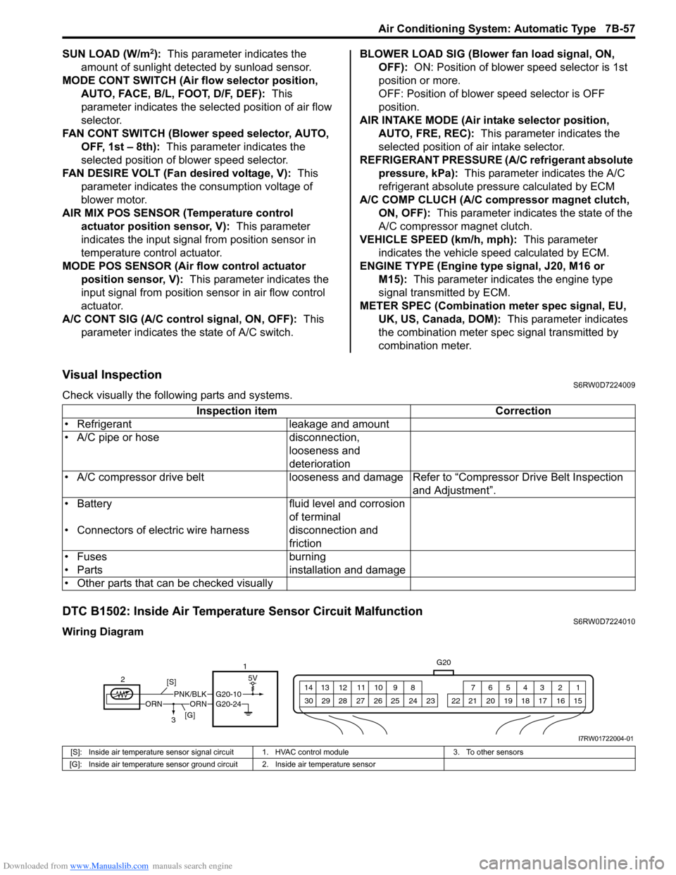
DTC B1502: Inside Air Temperature Sensor Circuit MalfunctionS6RW0D7224010
Wiring DiagramInspection item Correction
• Refrigerant leakage and amount
• A/C pipe or hose disconnection,
looseness and
deterioration
• A/C compressor drive belt looseness and damageRefer to “Compressor Drive Belt Inspection
and Adjustment”.
• Battery fluid level and corrosion
of terminal
• Connectors of electric wire harness disconnection and
friction
• Fuses burning
• Parts installation and damage
• Other parts that can be checked visually
5V
G20
1 2 3 4 5 6 7 8 9 10 11 12 13 14
15 16 17 18 19 20 21 24 23 22 25 26 27 28 29 30
ORNORNPNK/BLKG20-10
21
3 [S]
[G]
G20-24
I7RW01722004-01
[S]: Inside air temperature sensor signal circuit 1. HVAC control module 3. To other sensors
[G]: Inside air temperature sensor ground circuit 2. Inside air temperature sensor
Page 1009 of 1556

Downloaded from www.Manualslib.com manuals search engine Air Conditioning System: Automatic Type 7B-69
DTC B1541: Back-Up Power Supply Circuit MalfunctionS6RW0D7224018
Wiring Diagram
DTC Detecting Condition and Trouble Area
NOTE
When checking DTC after connecting battery cable, be sure to turn ignition switch from OFF to ON and
from ON to OFF at least once, or DTC B1541 will be detected.
DTC Troubleshooting
12V5V
WHTG20-7 2
31G201 2 3 4 5 6 7 8 9 10 11 12 13 14
15 16 17 18 19 20 21 24 23 22 25 26 27 28 29 30WHT/RED [B]
I7RW01722011-01
[B]: Back-up power supply circuit 2. Main fuse
1. HVAC control module 3. Circuit fuse
DTC Detecting Condition Trouble Area
• Back-up power supply voltage is lower than specified value continuously.
• When connect battery with vehicle and then, turn ignition switch to ON
position for first time.• Battery voltage supply circuit
• HVAC control module
Step Action Yes No
1Was “Air Conditioning System Check” performed?Go to Step 2. Go to “Air Conditioning
System Check”.
2DTC check
1) Turn ignition switch to ON position for 20 sec. or more.
2) Ignition switch turned OFF and connect scan tool to
DLC.
3) Turn ON ignition switch and check DTC.
Is there DTC B1541?Go to Step 3. Intermittent trouble.
Check for intermittent
referring to “Intermittent
and Poor Connection
Inspection in Section
00”.
3Battery voltage supply circuit check
1) Disconnect connector from HVAC control module with
ignition switch turned OFF.
2) Check for proper connection to back-up power supply
circuit terminal of HVAC control module connector.
3) If OK, measure voltage between back-up power supply
circuit terminal of HVAC control module connector and
vehicle body ground.
Is voltage 10 – 14 V?Substitute a known-
good HVAC control
module and recheck.Back-up power supply
circuit is open or
shorted to ground.