SUZUKI SX4 2006 1.G Service Manual PDF
Manufacturer: SUZUKI, Model Year: 2006, Model line: SX4, Model: SUZUKI SX4 2006 1.GPages: 1556, PDF Size: 37.31 MB
Page 71 of 1556

Downloaded from www.Manualslib.com manuals search engine Engine General Information and Diagnosis: 1A-21
Component Location
Electronic Control System Components LocationS6RW0D1103001
NOTE
The figure shows left-hand steering vehicle. For right-hand steering vehicle, parts with (*) are installed
at the opposite side.
H*E*
10
D
G* C
6A
B*
e
3*
12*
a8 13
b
1
5-1
d
2
11
g
4
7
9
i
j
Fh k f
n
c J
5
K*
14
I6RW0D110016-03
Information sensors Control devices Others
1. MAF and IAT sensor a: Fuel injector A: ECM
2. Electric throttle body assembly
(built-in throttle position sensor and throttle
actuator)b: EVAP canister purge valve B: Combination meter
3. Brake light switch c: Fuel pump relay C: EVAP canister
4. ECT sensor d: EGR valve (if equipped) D: A/C evaporator outlet air temp. sensor
(if equipped with A/C)
5. Heated oxygen sensor-1 e: Malfunction indicator lamp E: Data link connector
5-1. Heated oxygen sensor-2 (if equipped) f: Radiator cooling fan relay F: A/C compressor relay (if equipped with A/C)
6. Battery g: Ignition coil assembly (with ignitor) G: BCM (included in junction block assembly)
7. CMP sensor (for engine with VVT system) h: Main relay H: Immobilizer coil antenna
8. MAP sensor (if equipped) i: Oil control valve (for engine with VVT system) J: A/C refrigerant pressure sensor
(if equipped with A/C)
9. CKP sensor j: A/C condenser cooling fan relay K: TCM (for A/T model)
10. Fuel level sensor k: Starting motor control relay
11. Knock sensor m: Immobilizer indicator lamp
12. APP sensor n: Throttle actuator control relay
13. Front wheel speed sensor (RH, LH) (VSS)
14. CMP sensor (for engine without VVT system)
Page 72 of 1556

Downloaded from www.Manualslib.com manuals search engine 1A-22 Engine General Information and Diagnosis:
Diagnostic Information and Procedures
Engine and Emission Control System CheckS6RW0D1104001
Refer to the following items for the details of each step.
Step Action Yes No
1�) Customer complaint analysis
1) Perform customer complaint analysis referring to
“Customer Complaint Analysis”.
Was customer complaint analysis performed?Go to Step 2. Perform customer
complaint analysis.
2�) DTC / Freeze frame data check, record and clearance
1) Check for DTC (including pending DTC) referring to
“DTC / Freeze Frame Data Check, Record and
Clearance”.
Is there any DTC(s)?Print DTC and freeze
frame data or write them
down and clear them by
referring to “DTC
Clearance”, and go to
St ep 3 .Go to Step 4.
3�) Visual inspection
1) Perform visual inspection referring to “Visual Inspection”.
Is there any faulty condition?Repair or replace
malfunction part, and go
to Step 11.Go to Step 5.
4�) Visual inspection
1) Perform visual inspection referring to “Visual Inspection”.
Is there any faulty condition?Repair or replace
malfunction part, and go
to Step 11.Go to Step 8.
5�) Trouble symptom confirmation
1) Confirm trouble symptom referring to “Trouble Symptom
Confirmation”.
Is trouble symptom identified?Go to Step 6. Go to Step 7.
6�) Rechecking and record of DTC / Freeze frame data
1) Recheck for DTC and freeze frame data referring to
“DTC Check”.
Is there any DTC(s)?Go to Step 9. Go to Step 8.
7�) Rechecking and record of DTC / Freeze frame data
1) Recheck for DTC and freeze frame data referring to
“DTC Check”.
Is there any DTC(s)?Go to Step 9. Go to Step 10.
8�) Engine basic inspection and engine symptom
diagnosis
1) Check and repair according to “Engine Basic Inspection”
and “Engine Symptom Diagnosis”.
Are check and repair complete?Go to Step 11. Check and repair
malfunction part(s), and
go to Step 11.
9�) Troubleshooting for DTC
1) Check and repair according to applicable DTC diag. flow.
Are check and repair complete?Go to Step 11. Check and repair
malfunction part(s), and
go to Step 11.
10�) Intermittent problems check
1) Check for intermittent problems referring to “Intermittent
Problems Check”.
Is there any faulty condition?Repair or replace
malfunction part(s), and
go to Step 11.Go to Step 11.
Page 73 of 1556

Downloaded from www.Manualslib.com manuals search engine Engine General Information and Diagnosis: 1A-23
11�) Final confirmation test
1) Clear DTC if any.
2) Perform final confirmation test referring to “Final
Confirmation Test”.
Is there any problem symptom, DTC or abnormal condition?Go to Step 6. End. Step Action Yes No
Page 74 of 1556

Downloaded from www.Manualslib.com manuals search engine 1A-24 Engine General Information and Diagnosis:
Step 1: Customer Complaint Analysis
Record details of the problem (failure, complaint) and how it occurred as described by the customer. For this purpose,
use of such an inspection form will facilitate collecting information to the point required for proper analysis and
diagnosis.
Customer problem inspection form (Example)
NOTE
This form is a standard sample. It should be modified according to conditions characteristic of each
market.
I2RH01110010-02
Page 75 of 1556
Downloaded from www.Manualslib.com manuals search engine Engine General Information and Diagnosis: 1A-25
Step 2: DTC / Freeze Frame Data Check, Record and
Clearance
First, check DTC (including pending DTC), referring to
“DTC Check”. If DTC is indicated, print it and freeze
frame data or write them down and then clear them by
referring to “DTC Clearance”. DTC indicates malfunction
that occurred in the system but does not indicate
whether it exists now or it occurred in the past and the
normal condition has been restored now. To check which
case applies, check the symptom in question according
to Step 5 and recheck DTC according to Step 6 and 7.
Attempt to diagnose a trouble based on DTC in this step
only or failure to clear the DTC in this step will lead to
incorrect diagnosis, trouble diagnosis of a normal circuit
or difficulty in troubleshooting.
Step 3 and 4: Visual Inspection
As a preliminary step, be sure to perform visual check of
the items that support proper function of the engine
referring to “Visual Inspection”.
Step 5: Trouble Symptom Confirmation
Based on information obtained in “Step 1: Customer
Complaint Analysis: ” and “Step 2: DTC / Freeze Frame
Data Check, Record and Clearance: ”, confirm trouble
symptoms. Also, reconfirm DTC according to “DTC
Confirmation Procedure” described in each DTC diag.
flow.
Step 6 and 7: Rechecking and Record of DTC /
Freeze Frame Data
Refer to “DTC Check” for checking procedure.
Step 8: Engine Basic Inspection and Engine
Symptom Diagnosis
Perform basic engine check according to “Engine Basic
Inspection” first. When the end of the flow has been
reached, check the parts of the system suspected as a
possible cause referring to “Engine Symptom Diagnosis”
and based on symptoms appearing on the vehicle
(symptoms obtained through steps of customer
complaint analysis, trouble symptom confirmation and/or
basic engine check) and repair or replace faulty parts, if
any.
Step 9: Troubleshooting for DTC (See each DTC
Diag. Flow)
Based on the DTC indicated in Step 6 or 7 and referring
to the applicable DTC diag. flow, locate the cause of the
trouble, namely in a sensor, switch, wire harness,
connector, actuator, ECM or other part and repair or
replace faulty parts.Step 10: Intermittent Problems Check
Check parts where an intermittent trouble is easy to
occur (e.g., wire harness, connector, etc.), referring to
“Intermittent and Poor Connection Inspection in Section
00” and related circuit of DTC recorded in Step 2.
Step 11: Final Confirmation Test
Confirm that the problem symptom has gone and the
engine is free from any abnormal conditions. If what has
been repaired is related to the DTC, clear the DTC once,
perform DTC confirmation procedure and confirm that no
DTC is indicated.
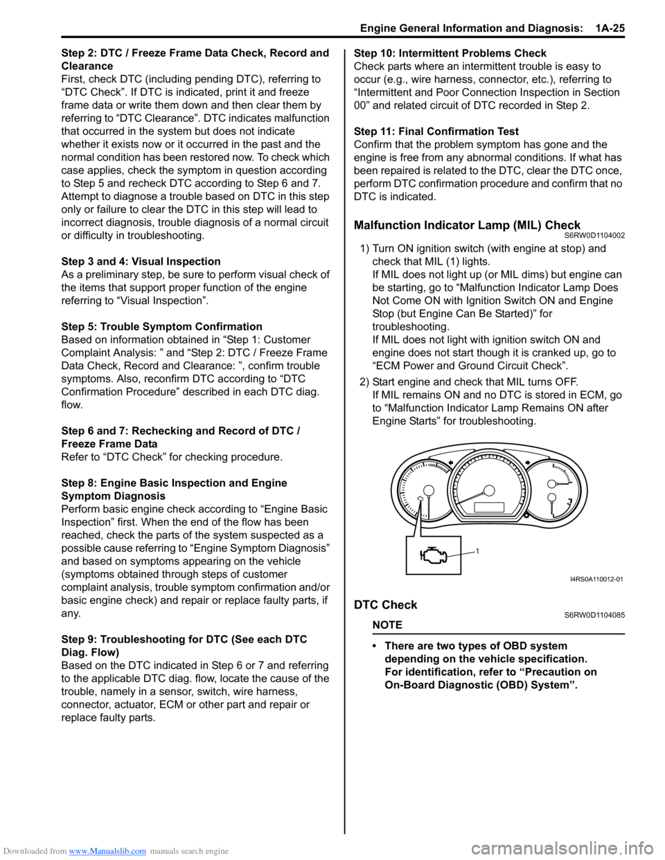
Malfunction Indicator Lamp (MIL) CheckS6RW0D1104002
1) Turn ON ignition switch (with engine at stop) and
check that MIL (1) lights.
If MIL does not light up (or MIL dims) but engine can
be starting, go to “Malfunction Indicator Lamp Does
Not Come ON with Ignition Switch ON and Engine
Stop (but Engine Can Be Started)” for
troubleshooting.
If MIL does not light with ignition switch ON and
engine does not start though it is cranked up, go to
“ECM Power and Ground Circuit Check”.
2) Start engine and check that MIL turns OFF.
If MIL remains ON and no DTC is stored in ECM, go
to “Malfunction Indicator Lamp Remains ON after
Engine Starts” for troubleshooting.
DTC CheckS6RW0D1104085
NOTE
• There are two types of OBD system
depending on the vehicle specification.
For identification, refer to “Precaution on
On-Board Diagnostic (OBD) System”.
1
I4RS0A110012-01
Page 76 of 1556
Downloaded from www.Manualslib.com manuals search engine 1A-26 Engine General Information and Diagnosis:
• The MIL is turned on when the ECM and/or
TCM detect malfunction(s). Each ECM and
TCM stores diagnostic information as the
diagnostic trouble code (DTC) in its
memory and outputs the DTC to the scan
tool.
Therefore, check both of the ECM and TCM
for any DTC with the scan tool because the
DTC stored in ECM and TCM is not read
and displayed at a time. However, each of
the ECM and TCM needs not to be checked
with the generic scan tool because the
DTC stored in ECM and TCM is read and
displayed at a time.
1) Prepare CAN communication OBD generic scan tool
or SUZUKI scan tool.
Special tool
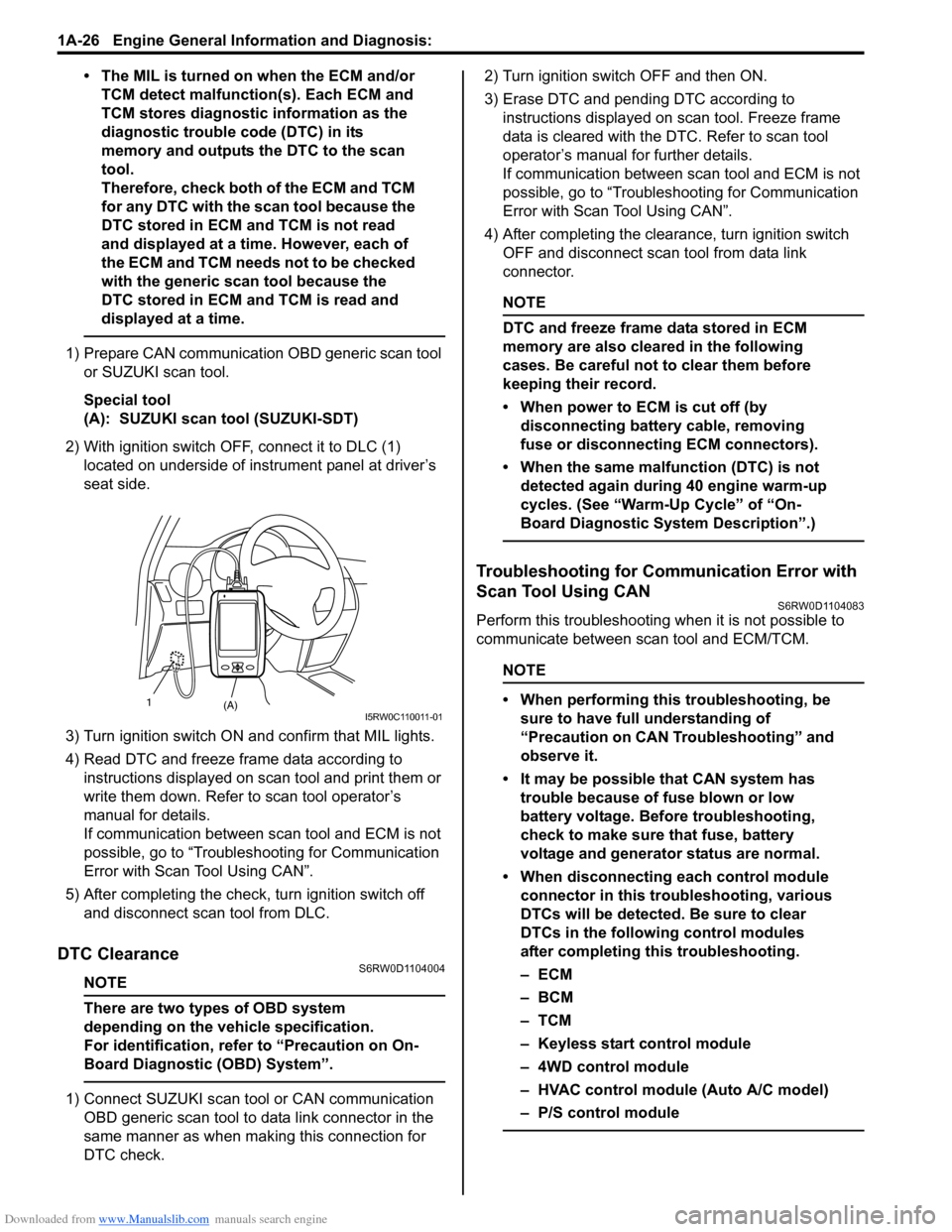
(A): SUZUKI scan tool (SUZUKI-SDT)
2) With ignition switch OFF, connect it to DLC (1)
located on underside of instrument panel at driver’s
seat side.
3) Turn ignition switch ON and confirm that MIL lights.
4) Read DTC and freeze frame data according to
instructions displayed on scan tool and print them or
write them down. Refer to scan tool operator’s
manual for details.
If communication between scan tool and ECM is not
possible, go to “Troubleshooting for Communication
Error with Scan Tool Using CAN”.
5) After completing the check, turn ignition switch off
and disconnect scan tool from DLC.
DTC ClearanceS6RW0D1104004
NOTE
There are two types of OBD system
depending on the vehicle specification.
For identification, refer to “Precaution on On-
Board Diagnostic (OBD) System”.
1) Connect SUZUKI scan tool or CAN communication
OBD generic scan tool to data link connector in the
same manner as when making this connection for
DTC check.2) Turn ignition switch OFF and then ON.
3) Erase DTC and pending DTC according to
instructions displayed on scan tool. Freeze frame
data is cleared with the DTC. Refer to scan tool
operator’s manual for further details.
If communication between scan tool and ECM is not
possible, go to “Troubleshooting for Communication
Error with Scan Tool Using CAN”.
4) After completing the clearance, turn ignition switch
OFF and disconnect scan tool from data link
connector.
NOTE
DTC and freeze frame data stored in ECM
memory are also cleared in the following
cases. Be careful not to clear them before
keeping their record.
• When power to ECM is cut off (by
disconnecting battery cable, removing
fuse or disconnecting ECM connectors).
• When the same malfunction (DTC) is not
detected again during 40 engine warm-up
cycles. (See “Warm-Up Cycle” of “On-
Board Diagnostic System Description”.)
Troubleshooting for Communication Error with
Scan Tool Using CAN
S6RW0D1104083
Perform this troubleshooting when it is not possible to
communicate between scan tool and ECM/TCM.
NOTE
• When performing this troubleshooting, be
sure to have full understanding of
“Precaution on CAN Troubleshooting” and
observe it.
• It may be possible that CAN system has
trouble because of fuse blown or low
battery voltage. Before troubleshooting,
check to make sure that fuse, battery
voltage and generator status are normal.
• When disconnecting each control module
connector in this troubleshooting, various
DTCs will be detected. Be sure to clear
DTCs in the following control modules
after completing this troubleshooting.
–ECM
–BCM
–TCM
– Keyless start control module
– 4WD control module
– HVAC control module (Auto A/C model)
– P/S control module
(A) 1I5RW0C110011-01
Page 77 of 1556
Downloaded from www.Manualslib.com manuals search engine Engine General Information and Diagnosis: 1A-27
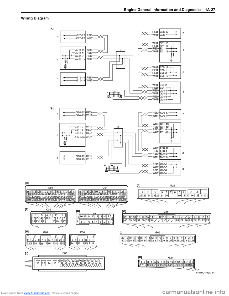
Wiring Diagram
61
2
3
REDWHT
REDWHT
REDWHT
REDWHT
E01-3E01-18
E08-1E08-12
E08-2E08-13
G05-1G05-3
RED
WHT
REDWHTG16-19G16-18
5
REDWHTG05-2G05-4
8
9
REDWHT G26-23G26-22
4
REDWHTG241-9
G241-7
G241-10
G241-67
REDWHT
REDWHT
C06-17C06-7
C01-12C01-13 [B]
61
2
3
REDWHT
REDWHT
REDWHT
REDWHT
REDWHT
E01-3E01-18
E08-1E08-12
E08-2E08-13
E04-1E04-2
G04-4G04-2
REDWHT
REDWHTG16-19G16-18
5
REDWHTG04-3G04-1
8
9
REDWHT G26-23G26-22
4
REDWHTG241-9
G241-7G241-10
G241-67
REDWHT
REDWHT
C06-17C06-7
C01-12C01-13 [A]
87 6543 219 10 11 12 13 14 15 16
[C]
[D]
21
3 4
18 19 5 6 7 10 11
17 20
47 46 49 50 51 21 22
5216 259
24 14
29
55 57 54 53
59
60
582
26 27 28 15
30
56
4832 31 34 35 36 37 40 42 39 38 44
45 43 41 331 12 13
238 3 4
18 19 5 6 7 10 11
17 20
47 46 49 50 5121 22
5216 259
24 14
29
55 57 54 53
59
605826
27
28 15
30
56
4832 31 34 35 36 37 40 42 39 38 44
45 43 41 3312 13
238 E01 C011 2 3 10 11 12
16 17 18 15 14 13 19 20 21 25 24 23 22 2654 6 7 8 9 [E]
G26
65
15 16 14 13 12 1143
24 23 212210 9 8 721
19 20 18 17 C06 [F]1 2 3 4 7 8 9 10 11 14 15 16
36 3435 24 23
21 22 28 27 2526 37 39 38 4018 17 13 12 19 20
[G]
G16
[K]
1
17G2413 2 4 5 6 7 8 9 10111213141516
19 18 20 2122 23 24 25 26 27 28 29 30 31 32 [J]E081 2 3 4 5 6 712 13 14 15 16 17 18 19 20 21 22
8 9 10 11 23 24 25 26
1 2 3 4 5 6 7
1 2 3 4 5 6 7 8 9 10 11
8 9 10 11
12 13 1412 13 14
15 16 17
18 19 20 21 22G04 E04 [H]1 [I]
G05
2 3 4 7 8 9 10 11 14 15 16
36 3435 24 23 2122 28 27 2526 37 39 38 4018 17 13 12 19 2065
33 32 31 30 29
I6RW0D110017-01
Page 78 of 1556
Downloaded from www.Manualslib.com manuals search engine 1A-28 Engine General Information and Diagnosis:
Trouble area
• Scan tool
• Connector related to CAN line (included in DLC)
• CAN line
• Power or ground circuit of DLC
• Control module communicated by CAN
–ECM
–TCM
– ABS control module
–BCM
– Combination meter
– Keyless start control module
– 4WD control module
• Power or ground circuit of control module communicated by CAN
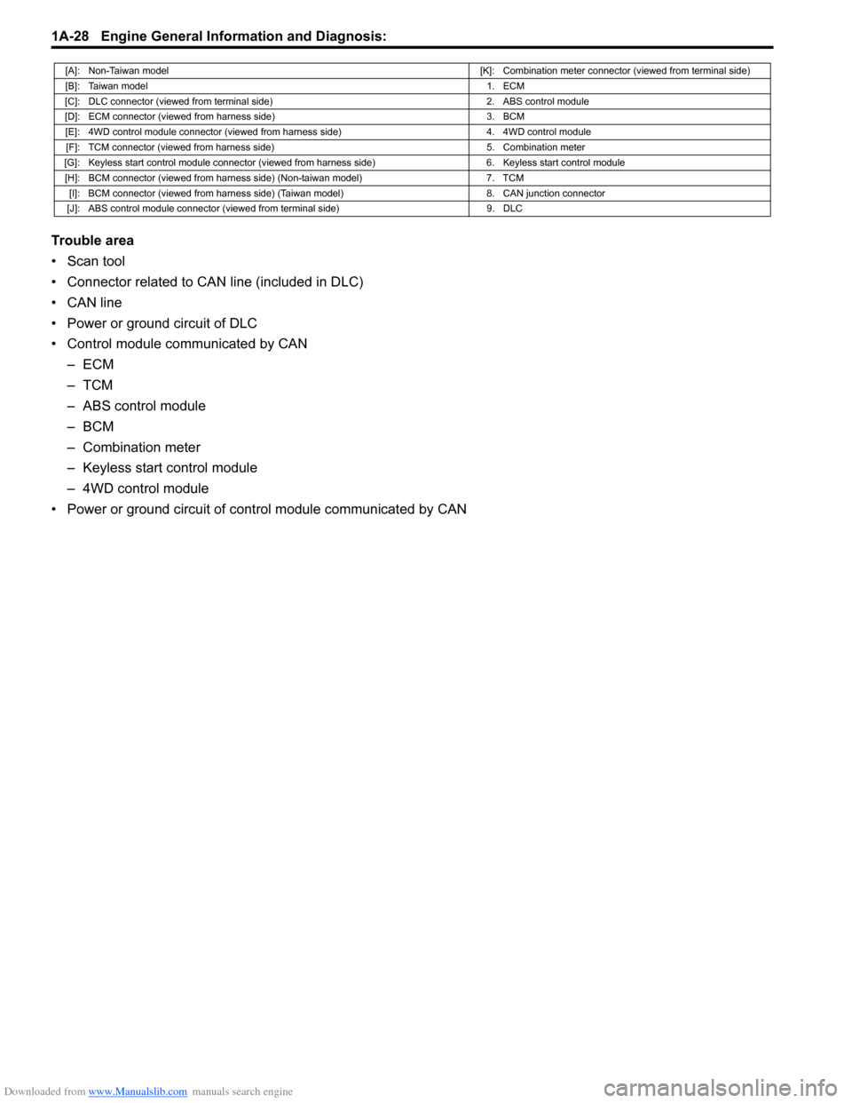
[A]: Non-Taiwan model[K]: Combination meter connector (viewed from terminal side)
[B]: Taiwan model1. ECM
[C]: DLC connector (viewed from terminal side) 2. ABS control module
[D]: ECM connector (viewed from harness side) 3. BCM
[E]: 4WD control module connector (viewed from harness side) 4. 4WD control module
[F]: TCM connector (viewed from harness side) 5. Combination meter
[G]: Keyless start control module connector (viewed from harness side) 6. Keyless start control module
[H]: BCM connector (viewed from harness side) (Non-taiwan model) 7. TCM
[I]: BCM connector (viewed from harness side) (Taiwan model) 8. CAN junction connector
[J]: ABS control module connector (viewed from terminal side) 9. DLC
Page 79 of 1556
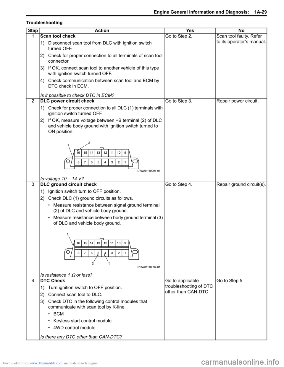
Downloaded from www.Manualslib.com manuals search engine Engine General Information and Diagnosis: 1A-29
Troubleshooting
Step Action Yes No
1Scan tool check
1) Disconnect scan tool from DLC with ignition switch
turned OFF.
2) Check for proper connection to all terminals of scan tool
connector.
3) If OK, connect scan tool to another vehicle of this type
with ignition switch turned OFF.
4) Check communication between scan tool and ECM by
DTC check in ECM.
Is it possible to check DTC in ECM?Go to Step 2. Scan tool faulty. Refer
to its operator’s manual.
2DLC power circuit check
1) Check for proper connection to all DLC (1) terminals with
ignition switch turned OFF.
2) If OK, measure voltage between +B terminal (2) of DLC
and vehicle body ground with ignition switch turned to
ON position.
Is voltage 10 – 14 V?Go to Step 3. Repair power circuit.
3DLC ground circuit check
1) Ignition switch turn to OFF position.
2) Check DLC (1) ground circuits as follows.
• Measure resistance between signal ground terminal
(2) of DLC and vehicle body ground.
• Measure resistance between body ground terminal (3)
of DLC and vehicle body ground.
Is resistance 1
Ω or less?Go to Step 4. Repair ground circuit(s).
4DTC Check
1) Turn ignition switch to OFF position.
2) Connect scan tool to DLC.
3) Check DTC in the following control modules that
communicate with scan tool by K-line.
•BCM
• Keyless start control module
• 4WD control module
Is there any DTC other than CAN-DTC?Go to applicable
troubleshooting of DTC
other than CAN-DTC.Go to Step 5.
2
9 10 11 12 13 14 15 16
1 2 3 4 5 6 7 8
1
I7RW01110096-01
23 1
9 10 11 12 13 14 15 16
1 2 3 4 5 6 7 8
I7RW01110097-01
Page 80 of 1556
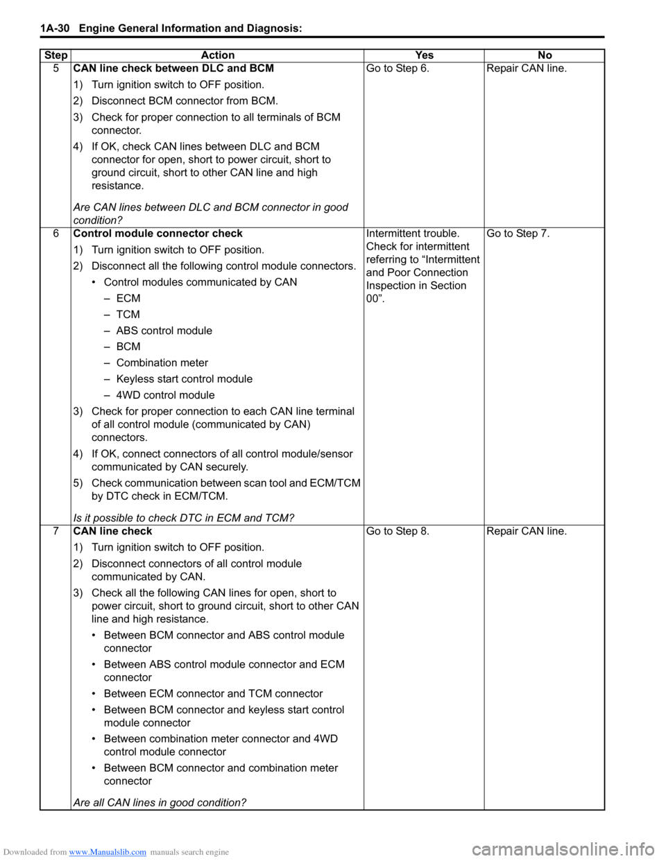
Downloaded from www.Manualslib.com manuals search engine 1A-30 Engine General Information and Diagnosis:
5CAN line check between DLC and BCM
1) Turn ignition switch to OFF position.
2) Disconnect BCM connector from BCM.
3) Check for proper connection to all terminals of BCM
connector.
4) If OK, check CAN lines between DLC and BCM
connector for open, short to power circuit, short to
ground circuit, short to other CAN line and high
resistance.
Are CAN lines between DLC and BCM connector in good
condition?Go to Step 6. Repair CAN line.
6Control module connector check
1) Turn ignition switch to OFF position.
2) Disconnect all the following control module connectors.
• Control modules communicated by CAN
–ECM
–TCM
– ABS control module
–BCM
– Combination meter
– Keyless start control module
– 4WD control module
3) Check for proper connection to each CAN line terminal
of all control module (communicated by CAN)
connectors.
4) If OK, connect connectors of all control module/sensor
communicated by CAN securely.
5) Check communication between scan tool and ECM/TCM
by DTC check in ECM/TCM.
Is it possible to check DTC in ECM and TCM?Intermittent trouble.
Check for intermittent
referring to “Intermittent
and Poor Connection
Inspection in Section
00”.Go to Step 7.
7CAN line check
1) Turn ignition switch to OFF position.
2) Disconnect connectors of all control module
communicated by CAN.
3) Check all the following CAN lines for open, short to
power circuit, short to ground circuit, short to other CAN
line and high resistance.
• Between BCM connector and ABS control module
connector
• Between ABS control module connector and ECM
connector
• Between ECM connector and TCM connector
• Between BCM connector and keyless start control
module connector
• Between combination meter connector and 4WD
control module connector
• Between BCM connector and combination meter
connector
Are all CAN lines in good condition?Go to Step 8. Repair CAN line. Step Action Yes No