Eps SUZUKI SX4 2006 1.G Service Workshop Manual
[x] Cancel search | Manufacturer: SUZUKI, Model Year: 2006, Model line: SX4, Model: SUZUKI SX4 2006 1.GPages: 1556, PDF Size: 37.31 MB
Page 24 of 1556
Downloaded from www.Manualslib.com manuals search engine 0A-1 General Information:
General Information
General Information
General Description
AbbreviationsS6RW0D0101001
A:
ABDC: After Bottom Dead Center
ABS: Anti-lock Brake System
AC: Alternating Current
A/C: Air Conditioning
A-ELR: Automatic-Emergency Locking Retractor
A/F: Air Fuel Mixture Ratio
ALR: Automatic Locking Retractor
API: American Petroleum Institute
APP sensor: Accelerator Pedal Position Sensor
A/T: Automatic Transmission, Automatic Transaxle
AT D C : After Top Dead Center
ATF: Automatic Transmission Fluid, Automatic
Transaxle Fluid
B:
B+: Battery Positive Voltage
BBDC: Before Bottom Dead Center
BCM: Body Electrical Control Module
BTDC: Before Top Dead Center
C:
CAN: Controller Area Network
CKT: Circuit
CKP Sensor: Crankshaft Position Sensor
CMP Sensor: Camshaft Position Sensor
CO: Carbon Monoxide
CPP Switch: Clutch Pedal Position Switch (Clutch
Switch, Clutch Start Switch)
CPU: Central Processing Unit
CRS: Child Restraint System
D:
DC: Direct Current
DLC: Data Link Connector (Assembly Line Diag. Link,
ALDL, Serial Data Link, SDL)
DOHC: Double Over Head Camshaft
DOJ: Double Offset Joint
DRL: Daytime Running Light
DTC: Diagnostic Trouble Code (Diagnostic Code)
E:
EBCM: Electronic Brake Control Module, ABS Control
Module
EBD: Electronic Brake Force Distribution
ECM: Engine Control Module
ECT Sensor: Engine Coolant Temperature Sensor
(Water Temp. Sensor, WTS)
EFE Heater: Early Fuel Evaporation Heater (Positive
Temperature Coefficient, PTC Heater)
EGR: Exhaust Gas Recirculation
EGRT Sensor: EGR Temperature Sensor (Recirculated
Exhaust Gas Temp. Sensor, REGTS)
EPS: Electronic Power Steering
EVAP: Evaporative Emission
EVAP Canister: Evaporative Emission Canister
(Charcoal Canister)F:
4WD: 4 Wheel Drive
G:
GEN: Generator
GND: Ground
GPS: Global Positioning System
H:
HAVC: Heating, Ventilating and Air Conditioning
HC: Hydrocarbons
HO2S: Heated Oxygen Sensor
I:
IAC Valve: Idle Air Control Valve (Idle Speed Control
Solenoid Valve, ISC Solenoid Valve)
IAT Sensor: Intake Air Temperature Sensor (Air
temperature Sensor, ATS)
ICM: Immobilizer Control Module
IG: Ignition
ISC Actuator: Idle Speed Control Actuator
L:
LH: Left Hand
LHD: Left Hand Drive vehicle
LSPV: Load Sensing Proportioning Valve
M:
MAF Sensor: Mass Air Flow Sensor (Air Flow Sensor,
AFS, Air Flow Meter, AFM)
MAP Sensor: Manifold Absolute Pressure Sensor
(Pressure Sensor, PS)
Max: Maximum
MFI: Multiport Fuel Injection (Multipoint Fuel Injection)
Min: Minimum
MIL: Malfunction Indicator Lamp (“SERVICE ENGINE
SOON” Light)
M/T: Manual Transmission, Manual Transaxle
N:
NOx: Nitrogen Oxides
O:
OBD: On-Board Diagnostic System (Self-Diagnosis
Function)
O/D: Overdrive
OHC: Over Head Camshaft
O2S: Oxygen Sensor
P:
PCM: Powertrain Control Module
PCV: Positive Crankcase Ventilation
PNP: Park / Neutral Position
P/S: Power Steering
PSP Switch: Power Steering Pressure Switch (P/S
Pressure Switch)
R:
RH: Right Hand
RHD: Right Hand Drive vehicle
Page 37 of 1556
Downloaded from www.Manualslib.com manuals search engine Maintenance and Lubrication: 0B-6
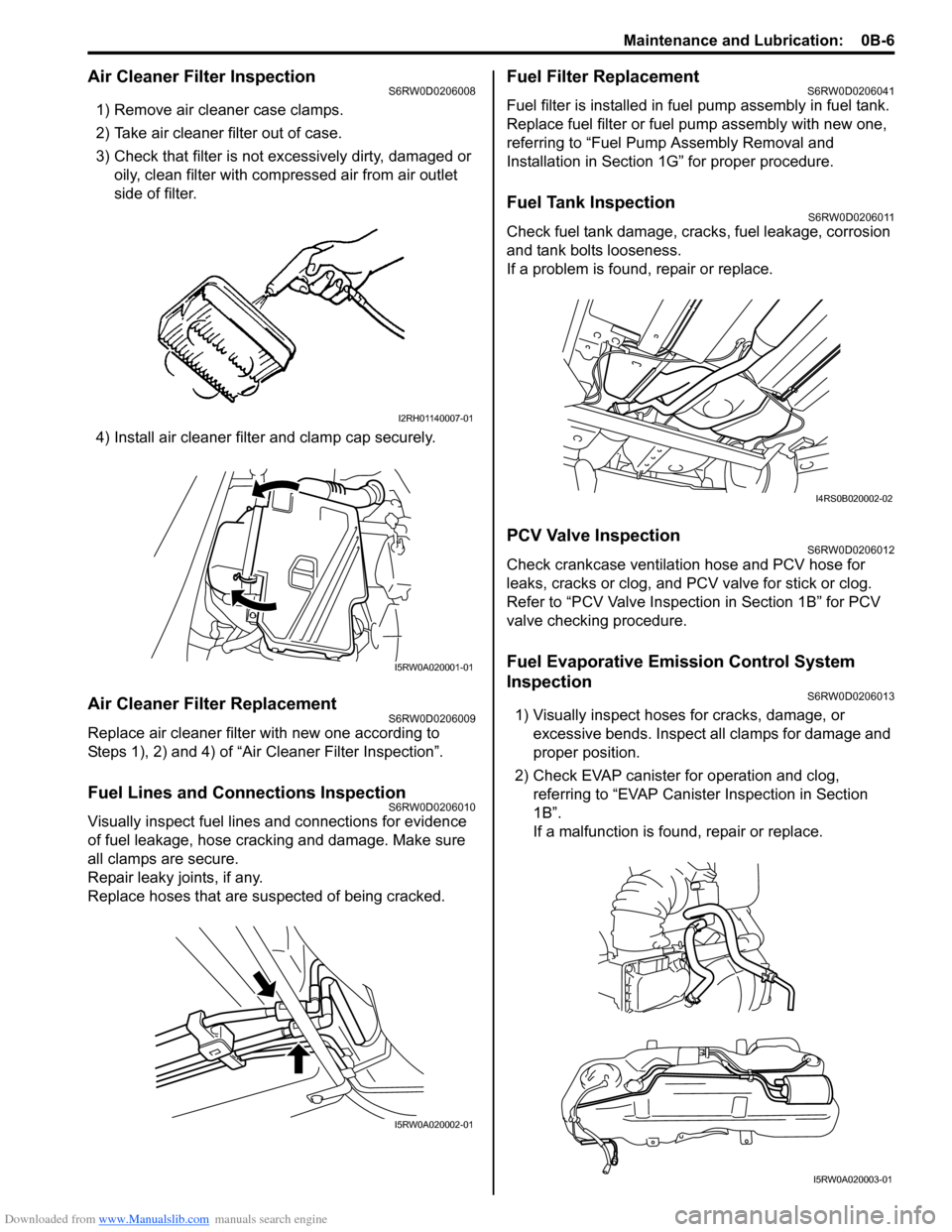
Air Cleaner Filter InspectionS6RW0D0206008
1) Remove air cleaner case clamps.
2) Take air cleaner filter out of case.
3) Check that filter is not excessively dirty, damaged or
oily, clean filter with compressed air from air outlet
side of filter.
4) Install air cleaner filter and clamp cap securely.
Air Cleaner Filter ReplacementS6RW0D0206009
Replace air cleaner filter with new one according to
Steps 1), 2) and 4) of “Air Cleaner Filter Inspection”.
Fuel Lines and Connections InspectionS6RW0D0206010
Visually inspect fuel lines and connections for evidence
of fuel leakage, hose cracking and damage. Make sure
all clamps are secure.
Repair leaky joints, if any.
Replace hoses that are suspected of being cracked.
Fuel Filter ReplacementS6RW0D0206041
Fuel filter is installed in fuel pump assembly in fuel tank.
Replace fuel filter or fuel pump assembly with new one,
referring to “Fuel Pump Assembly Removal and
Installation in Section 1G” for proper procedure.
Fuel Tank InspectionS6RW0D0206011
Check fuel tank damage, cracks, fuel leakage, corrosion
and tank bolts looseness.
If a problem is found, repair or replace.
PCV Valve InspectionS6RW0D0206012
Check crankcase ventilation hose and PCV hose for
leaks, cracks or clog, and PCV valve for stick or clog.
Refer to “PCV Valve Inspection in Section 1B” for PCV
valve checking procedure.
Fuel Evaporative Emission Control System
Inspection
S6RW0D0206013
1) Visually inspect hoses for cracks, damage, or
excessive bends. Inspect all clamps for damage and
proper position.
2) Check EVAP canister for operation and clog,
referring to “EVAP Canister Inspection in Section
1B”.
If a malfunction is found, repair or replace.
I2RH01140007-01
I5RW0A020001-01
I5RW0A020002-01
I4RS0B020002-02
I5RW0A020003-01
Page 41 of 1556
Downloaded from www.Manualslib.com manuals search engine Maintenance and Lubrication: 0B-10
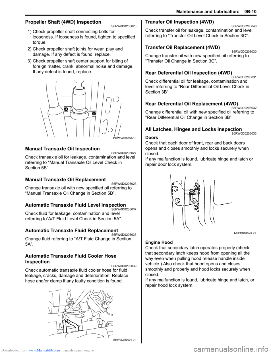
Propeller Shaft (4WD) InspectionS6RW0D0206026
1) Check propeller shaft connecting bolts for
looseness. If looseness is found, tighten to specified
torque.
2) Check propeller shaft joints for wear, play and
damage. If any defect is found, replace.
3) Check propeller shaft center support for biting of
foreign matter, crank, abnormal noise and damage.
If any defect is found, replace.
Manual Transaxle Oil InspectionS6RW0D0206027
Check transaxle oil for leakage, contamination and level
referring to “Manual Transaxle Oil Level Check in
Section 5B”.
Manual Transaxle Oil ReplacementS6RW0D0206028
Change transaxle oil with new specified oil referring to
“Manual Transaxle Oil Change in Section 5B”.
Automatic Transaxle Fluid Level InspectionS6RW0D0206037
Check fluid for leakage, contamination and level
referring to“A/T Fluid Level Check in Section 5A”.
Automatic Transaxle Fluid ReplacementS6RW0D0206038
Change fluid referring to “A/T Fluid Change in Section
5A”.
Automatic Transaxle Fluid Cooler Hose
Inspection
S6RW0D0206039
Check automatic transaxle fluid cooler hose for fluid
leakage, cracks, damage and deterioration. Replace
hose and/or clamp if any faulty condition is found.
Transfer Oil Inspection (4WD)S6RW0D0206040
Check transfer oil for leakage, contamination and level
referring to “Transfer Oil Level Check in Section 3C”.
Transfer Oil Replacement (4WD)S6RW0D0206030
Change transfer oil with new specified oil referring to
“Transfer Oil Change in Section 3C”.
Rear Deferential Oil Inspection (4WD)S6RW0D0206031
Check differential oil for leakage, contamination and
level referring to “Rear Differential Oil Level Check in
Section 3B”.
Rear Deferential Oil Replacement (4WD)S6RW0D0206032
Change differential oil with new specified oil referring to
“Rear Differential Oil Change in Section 3B”.
All Latches, Hinges and Locks InspectionS6RW0D0206033
Doors
Check that each door of front, rear and back doors
opens and closes smoothly and locks securely when
closed.
If any malfunction is found, lubricate hinge and latch or
repair door lock system.
Engine Hood
Check that secondary latch operates properly (check
that secondary latch keeps hood from opening all the
way even when pulling hood release handle inside
vehicle.) Also check that hood opens and closes
smoothly and properly and hood locks securely when
closed.
If any malfunction is found, lubricate hinge and latch, or
repair hood lock system.I5RW0A020006-01
I5RW0C020001-01
I2RH01020033-01
Page 67 of 1556
Downloaded from www.Manualslib.com manuals search engine Engine General Information and Diagnosis: 1A-17
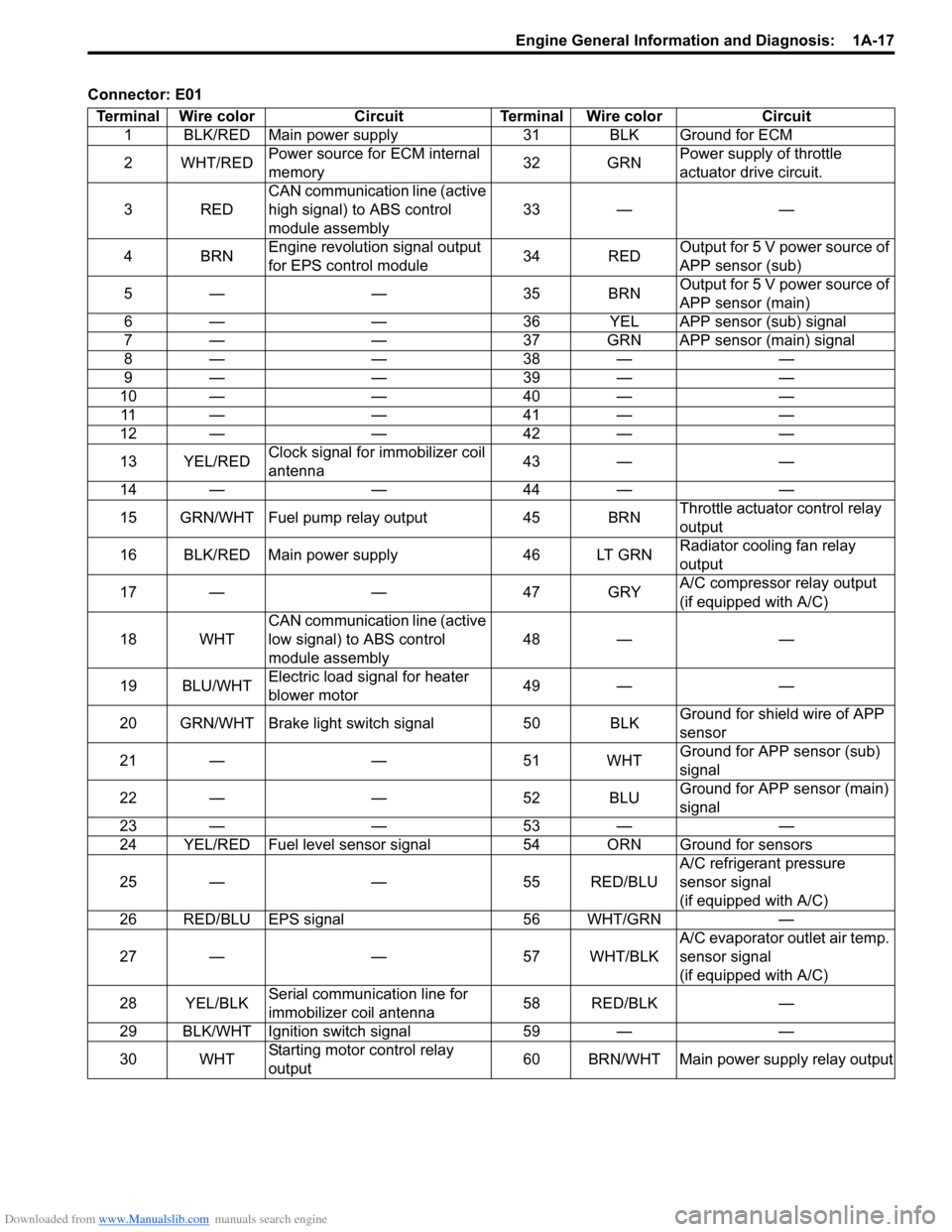
Connector: E01
Terminal Wire color Circuit Terminal Wire color Circuit
1 BLK/RED Main power supply 31 BLK Ground for ECM
2WHT/REDPower source for ECM internal
memory32 GRNPower supply of throttle
actuator drive circuit.
3REDCAN communication line (active
high signal) to ABS control
module assembly33 — —
4BRNEngine revolution signal output
for EPS control module34 REDOutput for 5 V power source of
APP sensor (sub)
5— — 35BRNOutput for 5 V power source of
APP sensor (main)
6 — — 36 YEL APP sensor (sub) signal
7 — — 37 GRN APP sensor (main) signal
8— — 38— —
9— — 39— —
10 — — 40 — —
11 — — 4 1 — —
12 — — 42 — —
13 YEL/REDClock signal for immobilizer coil
antenna43 — —
14 — — 44 — —
15 GRN/WHT Fuel pump relay output 45 BRNThrottle actuator control relay
output
16 BLK/RED Main power supply 46 LT GRNRadiator cooling fan relay
output
17 — — 47 GRYA/C compressor relay output
(if equipped with A/C)
18 WHTCAN communication line (active
low signal) to ABS control
module assembly48 — —
19 BLU/WHTElectric load signal for heater
blower motor49 — —
20 GRN/WHT Brake light switch signal 50 BLKGround for shield wire of APP
sensor
21 — — 51 WHTGround for APP sensor (sub)
signal
22 — — 52 BLUGround for APP sensor (main)
signal
23 — — 53 — —
24 YEL/RED Fuel level sensor signal 54 ORN Ground for sensors
25 — — 55 RED/BLUA/C refrigerant pressure
sensor signal
(if equipped with A/C)
26 RED/BLU EPS signal 56 WHT/GRN —
27 — — 57 WHT/BLKA/C evaporator outlet air temp.
sensor signal
(if equipped with A/C)
28 YEL/BLKSerial communication line for
immobilizer coil antenna58 RED/BLK —
29 BLK/WHT Ignition switch signal 59 — —
30 WHTStarting motor control relay
output60 BRN/WHT Main power supply relay output
Page 75 of 1556
Downloaded from www.Manualslib.com manuals search engine Engine General Information and Diagnosis: 1A-25
Step 2: DTC / Freeze Frame Data Check, Record and
Clearance
First, check DTC (including pending DTC), referring to
“DTC Check”. If DTC is indicated, print it and freeze
frame data or write them down and then clear them by
referring to “DTC Clearance”. DTC indicates malfunction
that occurred in the system but does not indicate
whether it exists now or it occurred in the past and the
normal condition has been restored now. To check which
case applies, check the symptom in question according
to Step 5 and recheck DTC according to Step 6 and 7.
Attempt to diagnose a trouble based on DTC in this step
only or failure to clear the DTC in this step will lead to
incorrect diagnosis, trouble diagnosis of a normal circuit
or difficulty in troubleshooting.
Step 3 and 4: Visual Inspection
As a preliminary step, be sure to perform visual check of
the items that support proper function of the engine
referring to “Visual Inspection”.
Step 5: Trouble Symptom Confirmation
Based on information obtained in “Step 1: Customer
Complaint Analysis: ” and “Step 2: DTC / Freeze Frame
Data Check, Record and Clearance: ”, confirm trouble
symptoms. Also, reconfirm DTC according to “DTC
Confirmation Procedure” described in each DTC diag.
flow.
Step 6 and 7: Rechecking and Record of DTC /
Freeze Frame Data
Refer to “DTC Check” for checking procedure.
Step 8: Engine Basic Inspection and Engine
Symptom Diagnosis
Perform basic engine check according to “Engine Basic
Inspection” first. When the end of the flow has been
reached, check the parts of the system suspected as a
possible cause referring to “Engine Symptom Diagnosis”
and based on symptoms appearing on the vehicle
(symptoms obtained through steps of customer
complaint analysis, trouble symptom confirmation and/or
basic engine check) and repair or replace faulty parts, if
any.
Step 9: Troubleshooting for DTC (See each DTC
Diag. Flow)
Based on the DTC indicated in Step 6 or 7 and referring
to the applicable DTC diag. flow, locate the cause of the
trouble, namely in a sensor, switch, wire harness,
connector, actuator, ECM or other part and repair or
replace faulty parts.Step 10: Intermittent Problems Check
Check parts where an intermittent trouble is easy to
occur (e.g., wire harness, connector, etc.), referring to
“Intermittent and Poor Connection Inspection in Section
00” and related circuit of DTC recorded in Step 2.
Step 11: Final Confirmation Test
Confirm that the problem symptom has gone and the
engine is free from any abnormal conditions. If what has
been repaired is related to the DTC, clear the DTC once,
perform DTC confirmation procedure and confirm that no
DTC is indicated.
Malfunction Indicator Lamp (MIL) CheckS6RW0D1104002
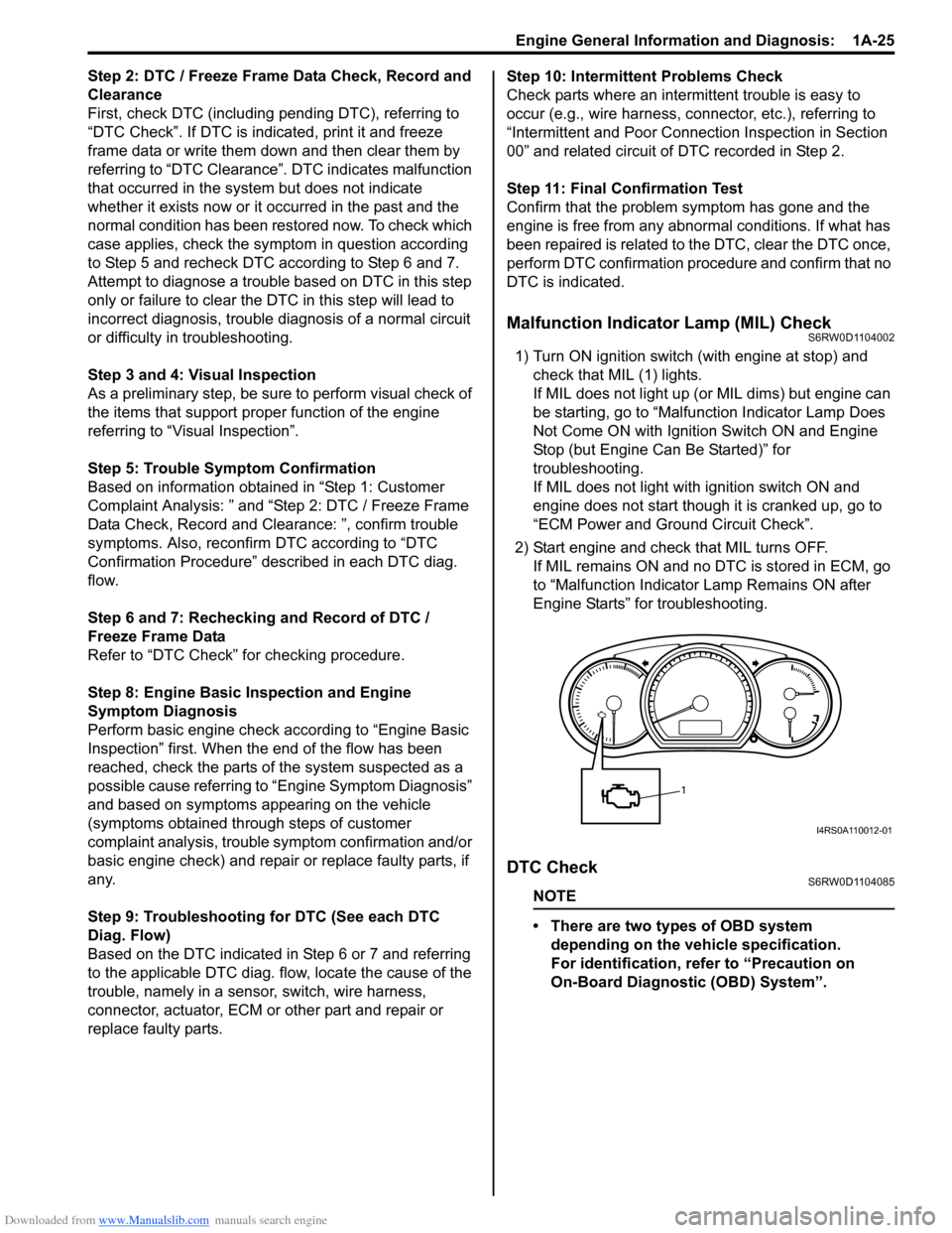
1) Turn ON ignition switch (with engine at stop) and
check that MIL (1) lights.
If MIL does not light up (or MIL dims) but engine can
be starting, go to “Malfunction Indicator Lamp Does
Not Come ON with Ignition Switch ON and Engine
Stop (but Engine Can Be Started)” for
troubleshooting.
If MIL does not light with ignition switch ON and
engine does not start though it is cranked up, go to
“ECM Power and Ground Circuit Check”.
2) Start engine and check that MIL turns OFF.
If MIL remains ON and no DTC is stored in ECM, go
to “Malfunction Indicator Lamp Remains ON after
Engine Starts” for troubleshooting.
DTC CheckS6RW0D1104085
NOTE
• There are two types of OBD system
depending on the vehicle specification.
For identification, refer to “Precaution on
On-Board Diagnostic (OBD) System”.
1
I4RS0A110012-01
Page 170 of 1556
Downloaded from www.Manualslib.com manuals search engine 1A-120 Engine General Information and Diagnosis:
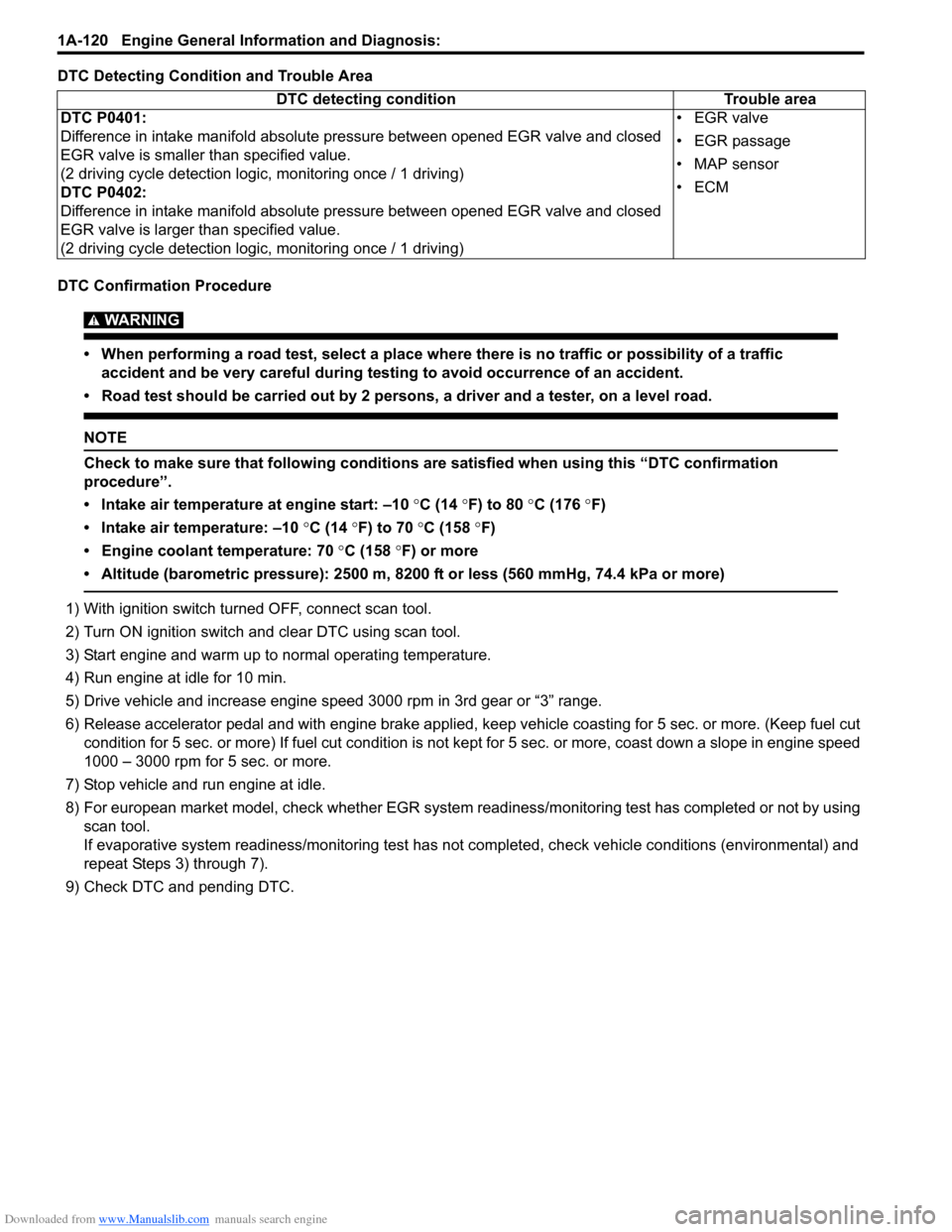
DTC Detecting Condition and Trouble Area
DTC Confirmation Procedure
WARNING!
• When performing a road test, select a place where there is no traffic or possibility of a traffic
accident and be very careful during testing to avoid occurrence of an accident.
• Road test should be carried out by 2 persons, a driver and a tester, on a level road.
NOTE
Check to make sure that following conditions are satisfied when using this “DTC confirmation
procedure”.
• Intake air temperature at engine start: –10 °C (14 °F) to 80 °C (176 °F)
• Intake air temperature: –10 °C (14 °F) to 70 °C (158 °F)
• Engine coolant temperature: 70 °C (158 °F) or more
• Altitude (barometric pressure): 2500 m, 8200 ft or less (560 mmHg, 74.4 kPa or more)
1) With ignition switch turned OFF, connect scan tool.
2) Turn ON ignition switch and clear DTC using scan tool.
3) Start engine and warm up to normal operating temperature.
4) Run engine at idle for 10 min.
5) Drive vehicle and increase engine speed 3000 rpm in 3rd gear or “3” range.
6) Release accelerator pedal and with engine brake applied, keep vehicle coasting for 5 sec. or more. (Keep fuel cut
condition for 5 sec. or more) If fuel cut condition is not kept for 5 sec. or more, coast down a slope in engine speed
1000 – 3000 rpm for 5 sec. or more.
7) Stop vehicle and run engine at idle.
8) For european market model, check whether EGR system readiness/monitoring test has completed or not by using
scan tool.
If evaporative system readiness/monitoring test has not completed, check vehicle conditions (environmental) and
repeat Steps 3) through 7).
9) Check DTC and pending DTC.DTC detecting condition Trouble area
DTC P0401:
Difference in intake manifold absolute pressure between opened EGR valve and closed
EGR valve is smaller than specified value.
(2 driving cycle detection logic, monitoring once / 1 driving)
DTC P0402:
Difference in intake manifold absolute pressure between opened EGR valve and closed
EGR valve is larger than specified value.
(2 driving cycle detection logic, monitoring once / 1 driving)• EGR valve
• EGR passage
• MAP sensor
•ECM
Page 175 of 1556
Downloaded from www.Manualslib.com manuals search engine Engine General Information and Diagnosis: 1A-125
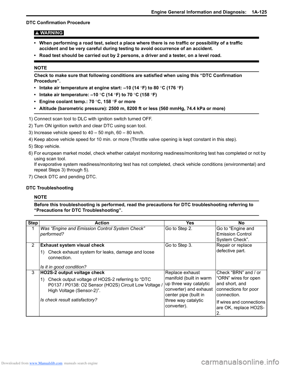
DTC Confirmation Procedure
WARNING!
• When performing a road test, select a place where there is no traffic or possibility of a traffic
accident and be very careful during testing to avoid occurrence of an accident.
• Road test should be carried out by 2 persons, a driver and a tester, on a level road.
NOTE
Check to make sure that following conditions are satisfied when using this “DTC Confirmation
Procedure”.
• Intake air temperature at engine start: –10 (14 °F) to 80 °C (176 °F)
• Intake air temperature: –10 °C (14 °F) to 70 °C (158 °F)
• Engine coolant temp.: 70 °C, 158 °F or more
• Altitude (barometric pressure): 2500 m, 8200 ft or less (560 mmHg, 74.4 kPa or more)
1) Connect scan tool to DLC with ignition switch turned OFF.
2) Turn ON ignition switch and clear DTC using scan tool.
3) Increase vehicle speed to 40 – 50 mph, 60 – 80 km/h.
4) Keep above vehicle speed for 10 min. or more (Throttle valve opening is kept constant in this step).
5) Stop vehicle.
6) For european market model, check whether catalyst monitoring readiness/monitoring test has completed or not by
using scan tool.
If evaporative system readiness/monitoring test has not completed, check vehicle conditions (environmental) and
repeat Steps 3) through 5).
7) Check DTC and pending DTC.
DTC Troubleshooting
NOTE
Before this troubleshooting is performed, read the precautions for DTC troubleshooting referring to
“Precautions for DTC Troubleshooting”.
Step Action Yes No
1Was “Engine and Emission Control System Check”
performed?Go to Step 2. Go to “Engine and
Emission Control
System Check”.
2Exhaust system visual check
1) Check exhaust system for leaks, damage and loose
connection.
Is it in good condition?Go to Step 3. Repair or replace
defective part.
3HO2S-2 output voltage check
1) Check output voltage of HO2S-2 referring to “DTC
P0137 / P0138: O2 Sensor (HO2S) Circuit Low Voltage /
High Voltage (Sensor-2)”.
Is check result satisfactory?Replace exhaust
manifold (built in warm
up three way catalytic
converter) and exhaust
center pipe (built in
three way catalytic
converter).Check “BRN” and / or
“ORN” wires for open
and short, and
connections for poor
connection.
If wires and connections
are OK, replace HO2S-
2.
Page 229 of 1556
Downloaded from www.Manualslib.com manuals search engine Engine General Information and Diagnosis: 1A-179
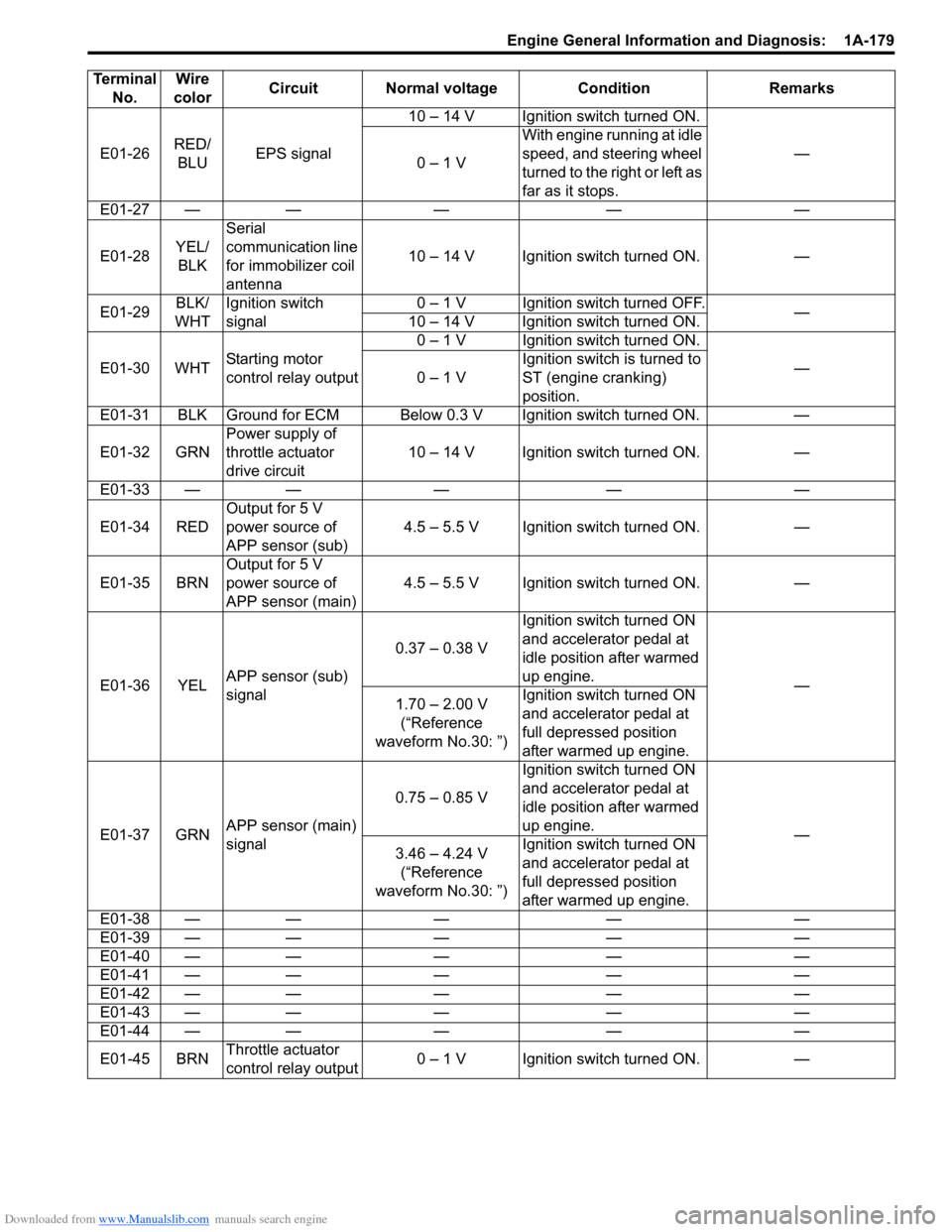
E01-26RED/
BLUEPS signal10 – 14 V Ignition switch turned ON.
—
0 – 1 VWith engine running at idle
speed, and steering wheel
turned to the right or left as
far as it stops.
E01-27 — — — — —
E01-28YEL/
BLKSerial
communication line
for immobilizer coil
antenna10 – 14 V Ignition switch turned ON. —
E01-29BLK/
WHTIgnition switch
signal0 – 1 V Ignition switch turned OFF.
—
10 – 14 V Ignition switch turned ON.
E01-30 WHTStarting motor
control relay output0 – 1 V Ignition switch turned ON.
—
0 – 1 VIgnition switch is turned to
ST (engine cranking)
position.
E01-31 BLK Ground for ECM Below 0.3 V Ignition switch turned ON. —
E01-32 GRNPower supply of
throttle actuator
drive circuit10 – 14 V Ignition switch turned ON. —
E01-33 — — — — —
E01-34 REDOutput for 5 V
power source of
APP sensor (sub)4.5 – 5.5 V Ignition switch turned ON. —
E01-35 BRNOutput for 5 V
power source of
APP sensor (main)4.5 – 5.5 V Ignition switch turned ON. —
E01-36 YELAPP sensor (sub)
signal0.37 – 0.38 VIgnition switch turned ON
and accelerator pedal at
idle position after warmed
up engine.
—
1.70 – 2.00 V
(“Reference
waveform No.30: ”)Ignition switch turned ON
and accelerator pedal at
full depressed position
after warmed up engine.
E01-37 GRNAPP sensor (main)
signal0.75 – 0.85 VIgnition switch turned ON
and accelerator pedal at
idle position after warmed
up engine.
—
3.46 – 4.24 V
(“Reference
waveform No.30: ”)Ignition switch turned ON
and accelerator pedal at
full depressed position
after warmed up engine.
E01-38 — — — — —
E01-39 — — — — —
E01-40 — — — — —
E01-41 — — — — —
E01-42 — — — — —
E01-43 — — — — —
E01-44 — — — — —
E01-45 BRNThrottle actuator
control relay output0 – 1 V Ignition switch turned ON. — Terminal
No.Wire
colorCircuit Normal voltage Condition Remarks
Page 272 of 1556
Downloaded from www.Manualslib.com manuals search engine 1C-4 Engine Electrical Devices:
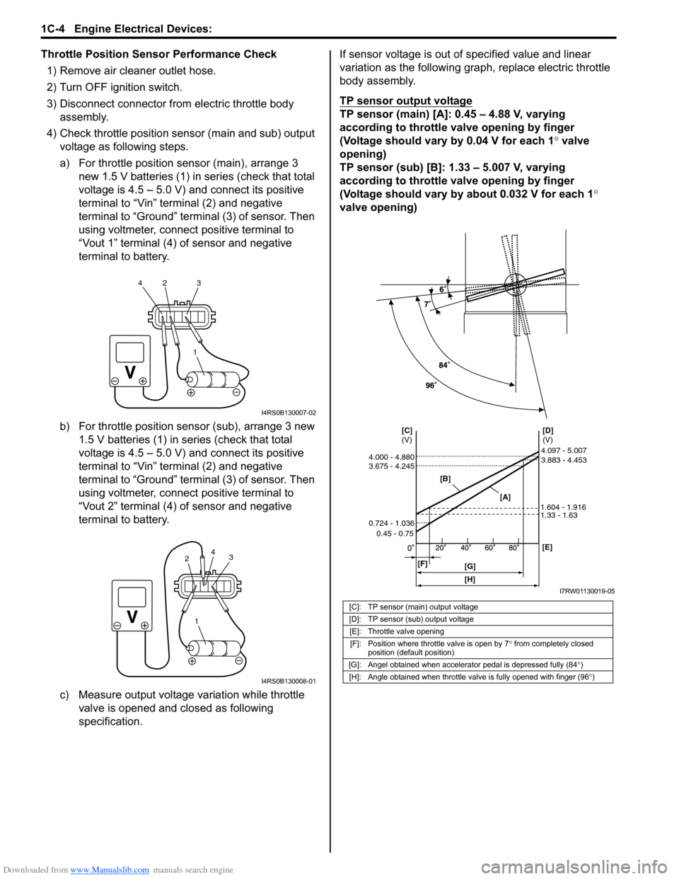
Throttle Position Sensor Performance Check
1) Remove air cleaner outlet hose.
2) Turn OFF ignition switch.
3) Disconnect connector from electric throttle body
assembly.
4) Check throttle position sensor (main and sub) output
voltage as following steps.
a) For throttle position sensor (main), arrange 3
new 1.5 V batteries (1) in series (check that total
voltage is 4.5 – 5.0 V) and connect its positive
terminal to “Vin” terminal (2) and negative
terminal to “Ground” terminal (3) of sensor. Then
using voltmeter, connect positive terminal to
“Vout 1” terminal (4) of sensor and negative
terminal to battery.
b) For throttle position sensor (sub), arrange 3 new
1.5 V batteries (1) in series (check that total
voltage is 4.5 – 5.0 V) and connect its positive
terminal to “Vin” terminal (2) and negative
terminal to “Ground” terminal (3) of sensor. Then
using voltmeter, connect positive terminal to
“Vout 2” terminal (4) of sensor and negative
terminal to battery.
c) Measure output voltage variation while throttle
valve is opened and closed as following
specification.If sensor voltage is out of specified value and linear
variation as the following graph, replace electric throttle
body assembly.
TP sensor output voltage
TP sensor (main) [A]: 0.45 – 4.88 V, varying
according to throttle valve opening by finger
(Voltage should vary by 0.04 V for each 1° valve
opening)
TP sensor (sub) [B]: 1.33 – 5.007 V, varying
according to throttle valve opening by finger
(Voltage should vary by about 0.032 V for each 1°
valve opening)
1 42 3
I4RS0B130007-02
1
3
24
I4RS0B130008-01
[C]: TP sensor (main) output voltage
[D]: TP sensor (sub) output voltage
[E]: Throttle valve opening
[F]: Position where throttle valve is open by 7° from completely closed
position (default position)
[G]: Angel obtained when accelerator pedal is depressed fully (84°)
[H]: Angle obtained when throttle valve is fully opened with finger (96°)
[B]
[A][D]
(V) [C]
(V)
[F]
[G][E] 0.45 - 0.75 0.724 - 1.036 3.675 - 4.245 4.000 - 4.880
1.33 - 1.63 1.604 - 1.9163.883 - 4.453 4.097 - 5.007
[H]
I7RW01130019-05
Page 273 of 1556
Downloaded from www.Manualslib.com manuals search engine Engine Electrical Devices: 1C-5
Electric Throttle Body System CalibrationS6RW0D1306004
NOTE
If the service described under the
“Precautions of Electric Throttle Body
System Calibration in Section 1A” is
performed, calibrate electric throttle body
system as follows.
1) If electric throttle body assembly and/or accelerator
pedal position (APP) sensor assembly are replaced,
perform following steps.
a) Disconnect negative cable at battery for 20
seconds or more for the purpose of clearing
calibration data of closed throttle position from
memory in ECM.
b) Connect negative cable to battery.
2) Keep ignition switch at ON position for 5 seconds or
more without running engine.
Accelerator Pedal Position (APP) Sensor
Assembly On-Vehicle Inspection
S6RW0D1306005
1) Check that APP sensor assembly has been mounted
to vehicle body properly (no pinched floor carpet,
etc.).
If mounting is not properly, reinstall APP sensor
assembly properly referring to “Accelerator Pedal
Position (APP) Sensor Assembly Removal and
Installation”.
2) Connect scan tool to DLC with ignition switch turned
OFF.
3) Turn ON ignition switch and select “Data List” mode
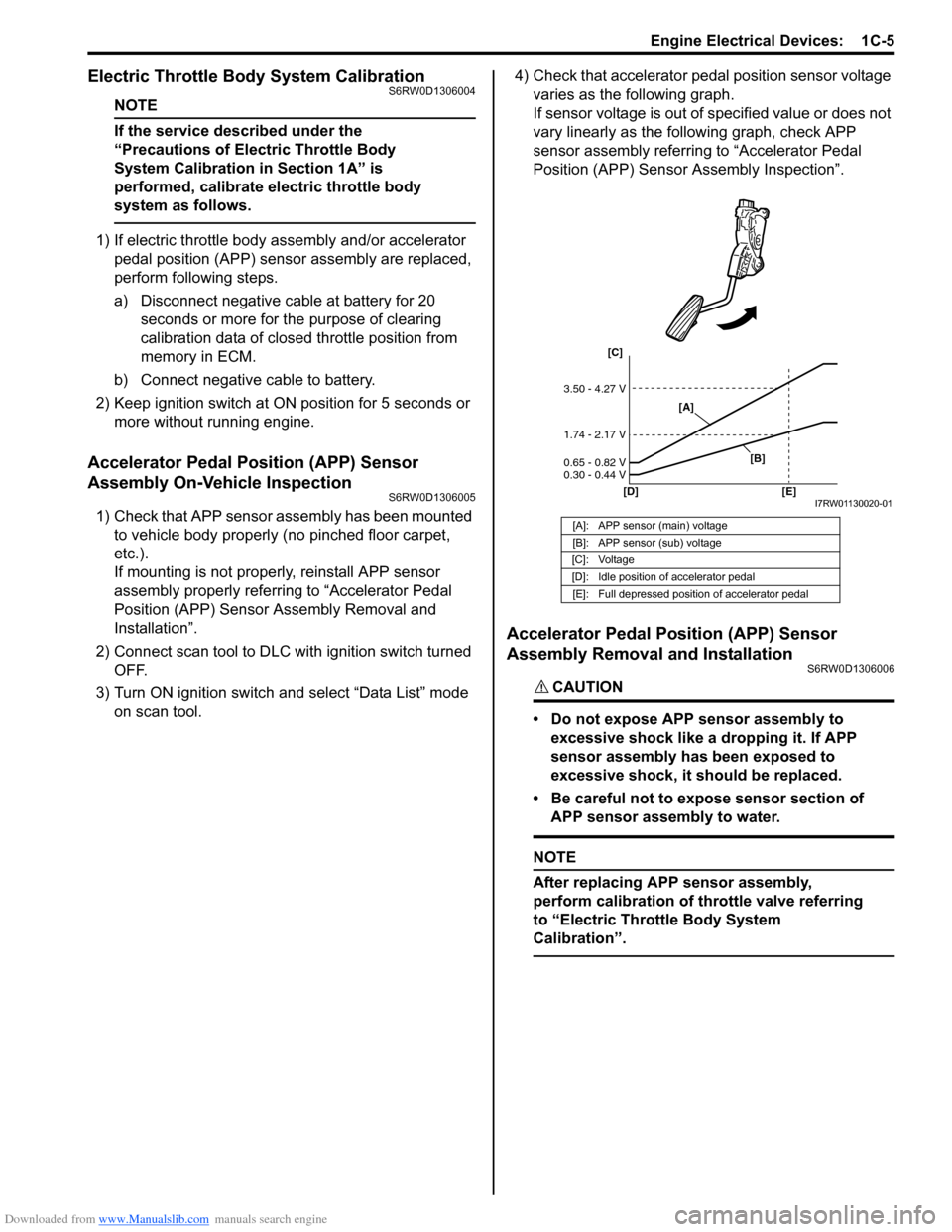
on scan tool.4) Check that accelerator pedal position sensor voltage
varies as the following graph.
If sensor voltage is out of specified value or does not
vary linearly as the following graph, check APP
sensor assembly referring to “Accelerator Pedal
Position (APP) Sensor Assembly Inspection”.
Accelerator Pedal Position (APP) Sensor
Assembly Removal and Installation
S6RW0D1306006
CAUTION!
• Do not expose APP sensor assembly to
excessive shock like a dropping it. If APP
sensor assembly has been exposed to
excessive shock, it should be replaced.
• Be careful not to expose sensor section of
APP sensor assembly to water.
NOTE
After replacing APP sensor assembly,
perform calibration of throttle valve referring
to “Electric Throttle Body System
Calibration”.
[A]: APP sensor (main) voltage
[B]: APP sensor (sub) voltage
[C]: Voltage
[D]: Idle position of accelerator pedal
[E]: Full depressed position of accelerator pedal
[C]
[D] [E]
3.50 - 4.27 V
1.74 - 2.17 V
0.65 - 0.82 V
0.30 - 0.44 V
[A]
[B]
I7RW01130020-01