lock TOYOTA AYGO 2021 Owners Manual
[x] Cancel search | Manufacturer: TOYOTA, Model Year: 2021, Model line: AYGO, Model: TOYOTA AYGO 2021Pages: 546, PDF Size: 81 MB
Page 408 of 546
4067-3. Do-it-yourself maintenance
AYGO_OM_Europe_OM9A012E■
How to initialize the tire pressure warning system
Park the vehicle in a safe place and turn the engine switch to the
“LOCK” position (vehicles without a smart entry & start system)
or off (vehicles with a smart entry & start system).
Initialization cannot be performed while the vehicle is moving.
Adjust the tire inflation pressure to the specified cold tire inflation
pressure level. (P. 518)
Make sure to adjust the tire pressure to the specified cold tire inflation
pressure level. The tire pressure warning system will operate based on
this pressure level.
Turn the engine switch to the “ON” position (vehicles without a
smart entry & start system) or IGNITION ON mode (vehicles with
a smart entry & start system).
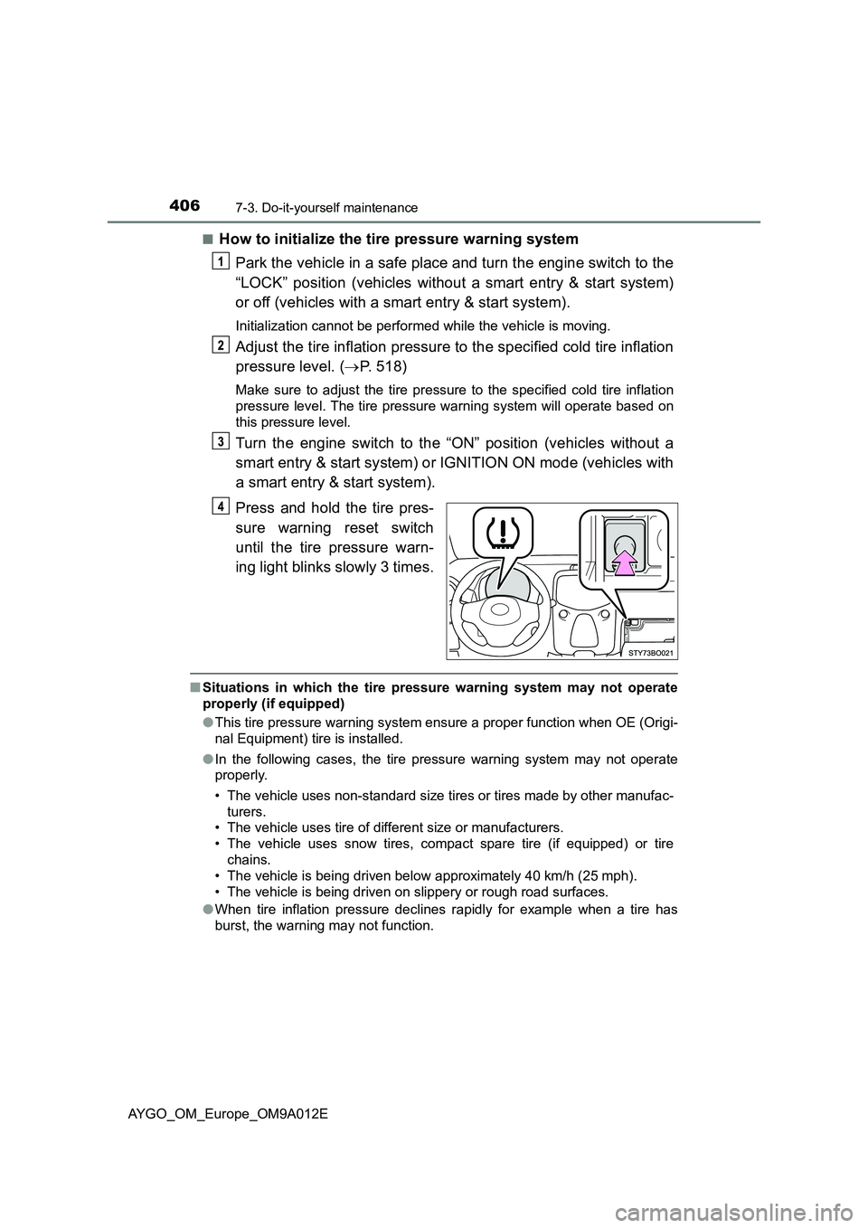
Press and hold the tire pres-
sure warning reset switch
until the tire pressure warn-
ing light blinks slowly 3 times.
■Situations in which the tire pressure warning system may not operate
properly (if equipped)
●This tire pressure warning system ensure a proper function when OE (Origi-
nal Equipment) tire is installed.
●In the following cases, the tire pressure warning system may not operate
properly.
• The vehicle uses non-standard size tires or tires made by other manufac-
turers.
• The vehicle uses tire of different size or manufacturers.
• The vehicle uses snow tires, compact spare tire (if equipped) or tire
chains.
• The vehicle is being driven below approximately 40 km/h (25 mph).
• The vehicle is being driven on slippery or rough road surfaces.
●When tire inflation pressure declines rapidly for example when a tire has
burst, the warning may not function.
Page 416 of 546
4147-3. Do-it-yourself maintenance
AYGO_OM_Europe_OM9A012E
Air conditioning filter
Vehicles without a smart entry & start system:
Turn the engine switch to the “LOCK” position.
Vehicles with a smart entry & start system:
Turn the engine switch off.
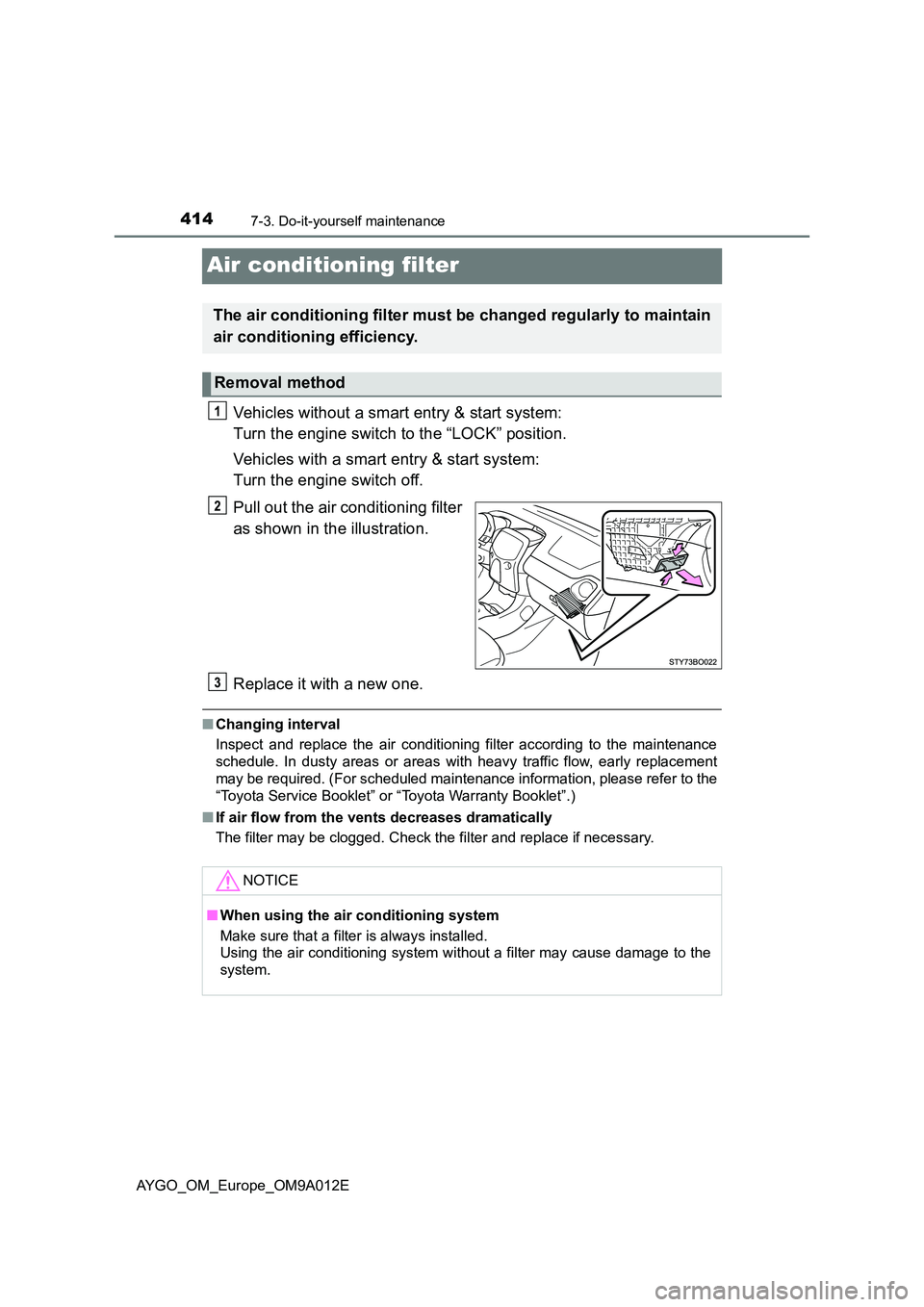
Pull out the air conditioning filter
as shown in the illustration.
Replace it with a new one.
■ Changing interval
Inspect and replace the air conditioning filter according to the maintenance
schedule. In dusty areas or areas with heavy traffic flow, early replacement
may be required. (For scheduled maintenance information, please refer to the
“Toyota Service Booklet” or “Toyota Warranty Booklet”.)
■ If air flow from the vents decreases dramatically
The filter may be clogged. Check the filter and replace if necessary.
The air conditioning filter must be changed regularly to maintain
air conditioning efficiency.
Removal method
NOTICE
■ When using the air conditioning system
Make sure that a filter is always installed.
Using the air conditi oning system without a filter may cause damage to the
system.
Page 420 of 546
4187-3. Do-it-yourself maintenance
AYGO_OM_Europe_OM9A012E
Checking and replacing fuses
Vehicles without a smart entry & start system:
Turn the engine switch to the “LOCK” position.
Vehicles with a smart entry & start system:
Turn the engine switch off.
After a system failure, see “Fuse layout and amperage ratings” for
details about which fuse to check. (P. 420)
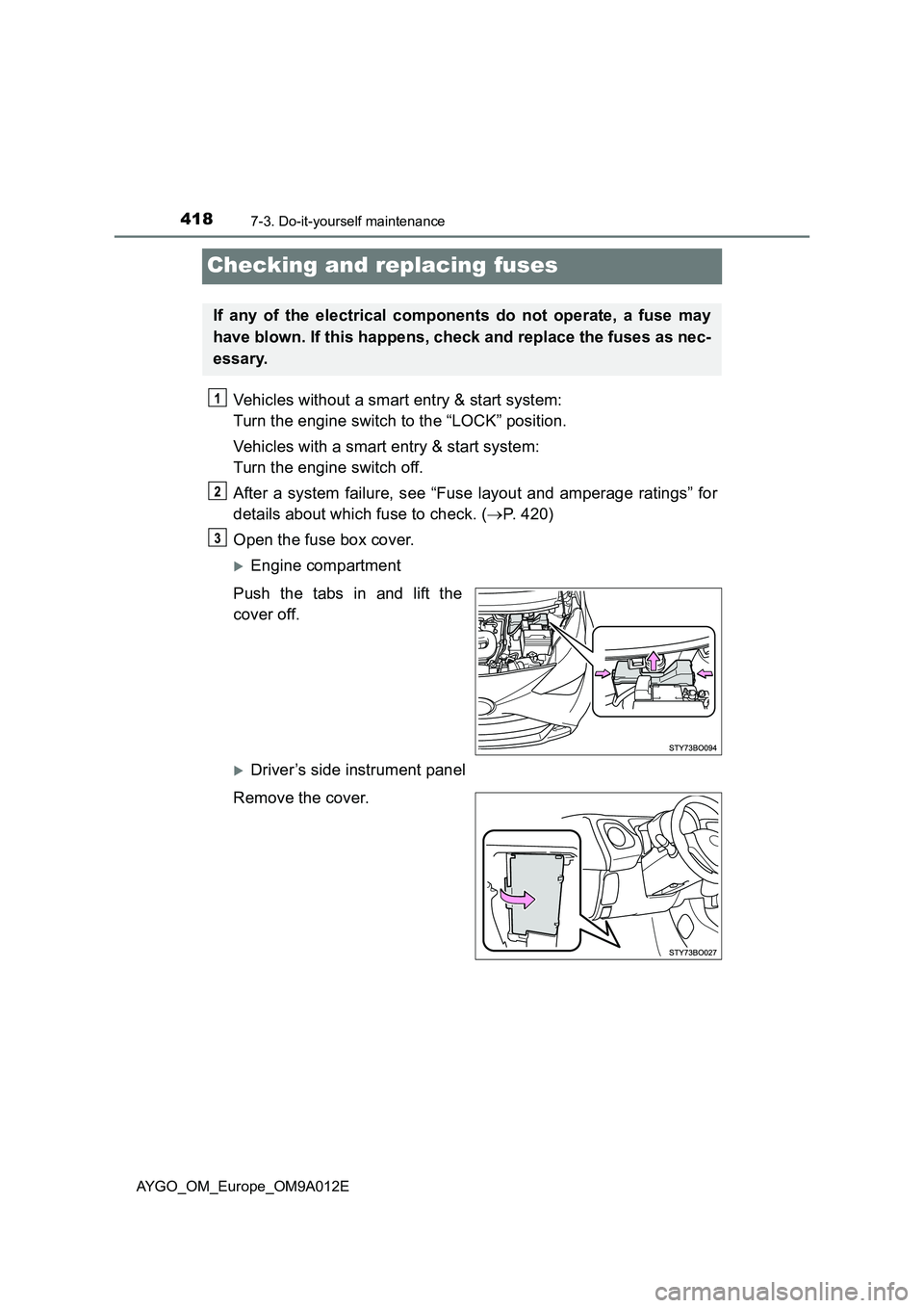
Open the fuse box cover.
Engine compartment
Push the tabs in and lift the
cover off.
Driver’s side instrument panel
Remove the cover.
If any of the electrical components do not operate, a fuse may
have blown. If this happens, check and replace the fuses as nec-
essary.
Page 423 of 546

4217-3. Do-it-yourself maintenance
7
Maintenance and care
AYGO_OM_Europe_OM9A012E
11ECU-B NO.4*17.5Multi-mode manual transmission
12AM2 NO.27.5Multiport fuel injection system/sequential
multiport fuel injection system
13AM2 NO.37.5Smart entry & start system
14ICS*27.5Charging system
15ST30Starting system
16STRG LOCK7.5Steering lock system
17H-LP-MAIN25H-LP RH-LO, H-LP LH-LO, H-LP RH-HI,
H-LP LH-HI
18WIPER-S*27.5Multiport fuel injection system/sequential
multiport fuel injection system
19STA7.5
Multiport fuel injection system/sequential
multiport fuel injection system, starting
system, multi-mode manual transmis-
sion, Stop & Start system
20ECU-B NO.315Audio system, smart entry & start system
21ECU-B NO.17.5Gauges and meters
22ECU-B NO.27.5Vehicle stability control system
23J/B60Instrument fuse box
24ALT125
DEF, S/HTR F/R, S/HTR F/L, CANVAS
TOP, ABS NO.1, ABS NO.2, RDI NO.1,
FOG FR, DRL
25AMT*150Multi-mode manual transmission
BBC*240Stop & Start system
FuseAmpereCircuit
Page 424 of 546
4227-3. Do-it-yourself maintenance
AYGO_OM_Europe_OM9A012E
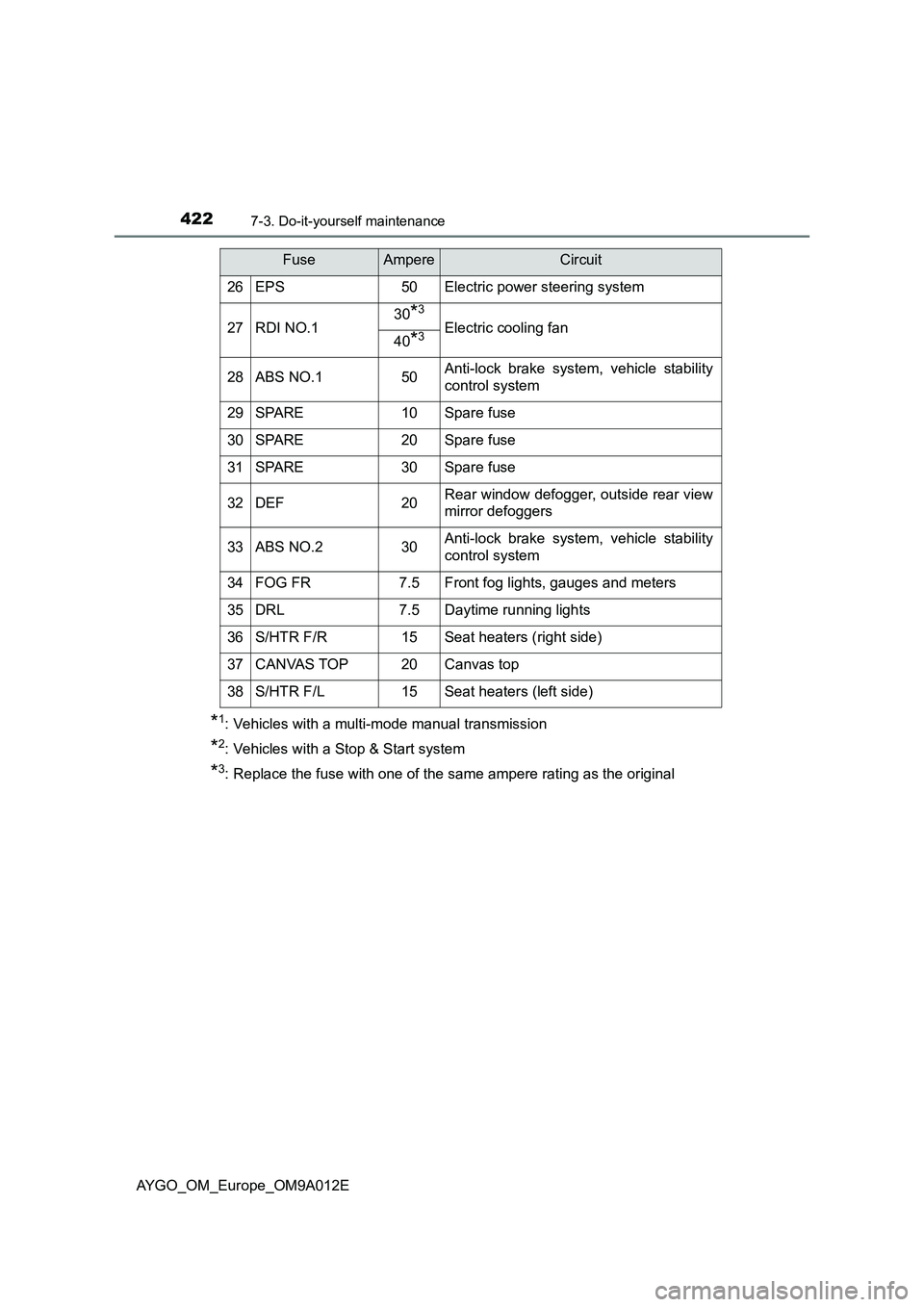
*1: Vehicles with a multi-mode manual transmission
*2: Vehicles with a Stop & Start system
*3: Replace the fuse with one of the same ampere rating as the original
26EPS50Electric power steering system
27RDI NO.130*3
Electric cooling fan40*3
28ABS NO.150Anti-lock brake system, vehicle stability
control system
29SPARE10Spare fuse
30SPARE20Spare fuse
31SPARE30Spare fuse
32DEF20Rear window defogger, outside rear view
mirror defoggers
33ABS NO.230Anti-lock brake system, vehicle stability
control system
34FOG FR7.5Front fog lights, gauges and meters
35DRL7.5Daytime running lights
36S/HTR F/R15Seat heaters (right side)
37CANVAS TOP20Canvas top
38S/HTR F/L15Seat heaters (left side)
FuseAmpereCircuit
Page 425 of 546
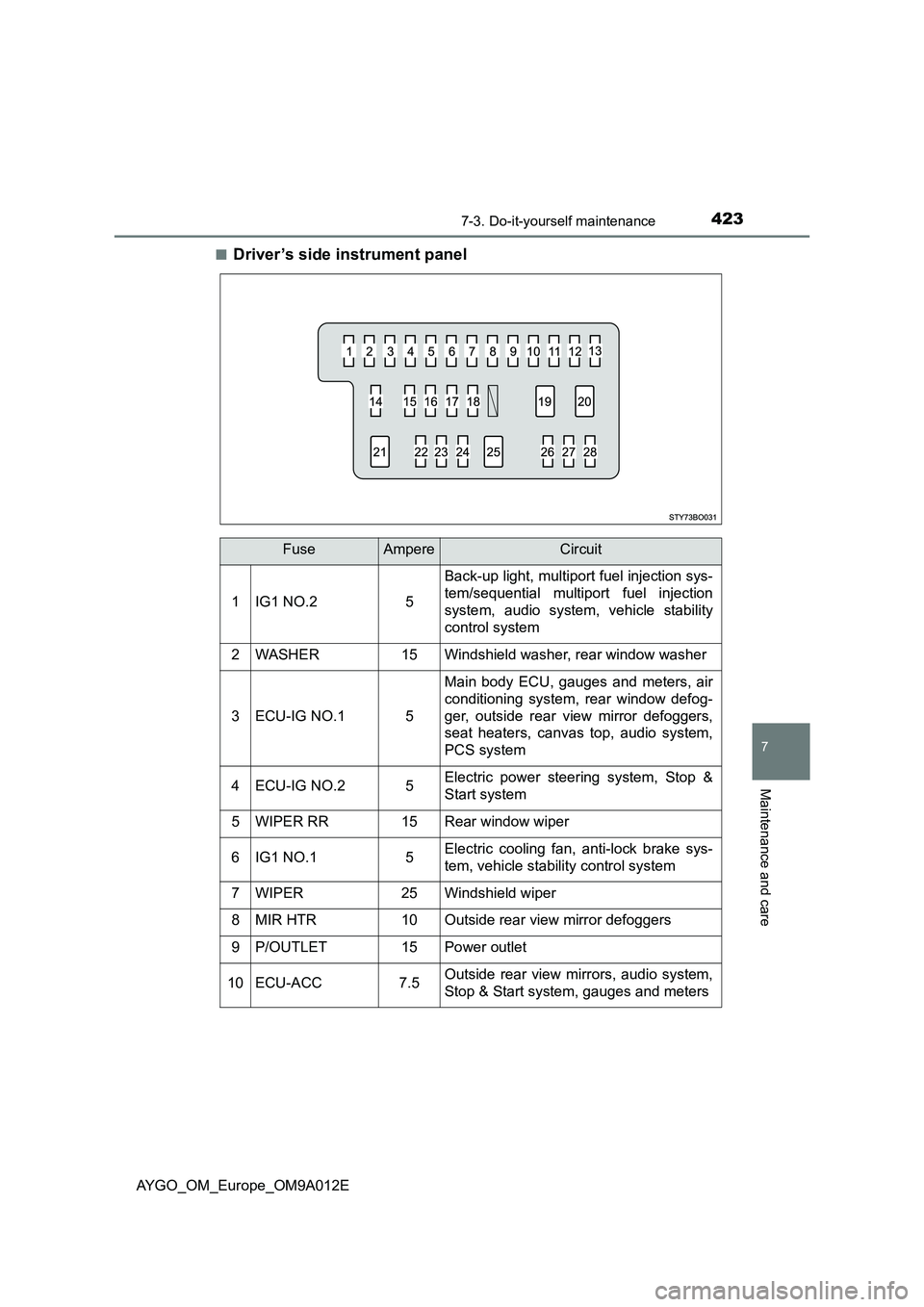
4237-3. Do-it-yourself maintenance
7
Maintenance and care
AYGO_OM_Europe_OM9A012E■
Driver ’s side instrument panel
FuseAmpereCircuit
1IG1 NO.25
Back-up light, multiport fuel injection sys-
tem/sequential multiport fuel injection
system, audio system, vehicle stability
control system
2WASHER15Windshield washer, rear window washer
3ECU-IG NO.15
Main body ECU, gauges and meters, air
conditioning system, rear window defog-
ger, outside rear view mirror defoggers,
seat heaters, canvas top, audio system,
PCS system
4ECU-IG NO.25Electric power steering system, Stop &
Start system
5WIPER RR15Rear window wiper
6IG1 NO.15Electric cooling fan, anti-lock brake sys-
tem, vehicle stability control system
7WIPER25Windshield wiper
8MIR HTR10Outside rear view mirror defoggers
9P/OUTLET15Power outlet
10ECU-ACC7.5Outside rear view mirrors, audio system,
Stop & Start system, gauges and meters
Page 426 of 546
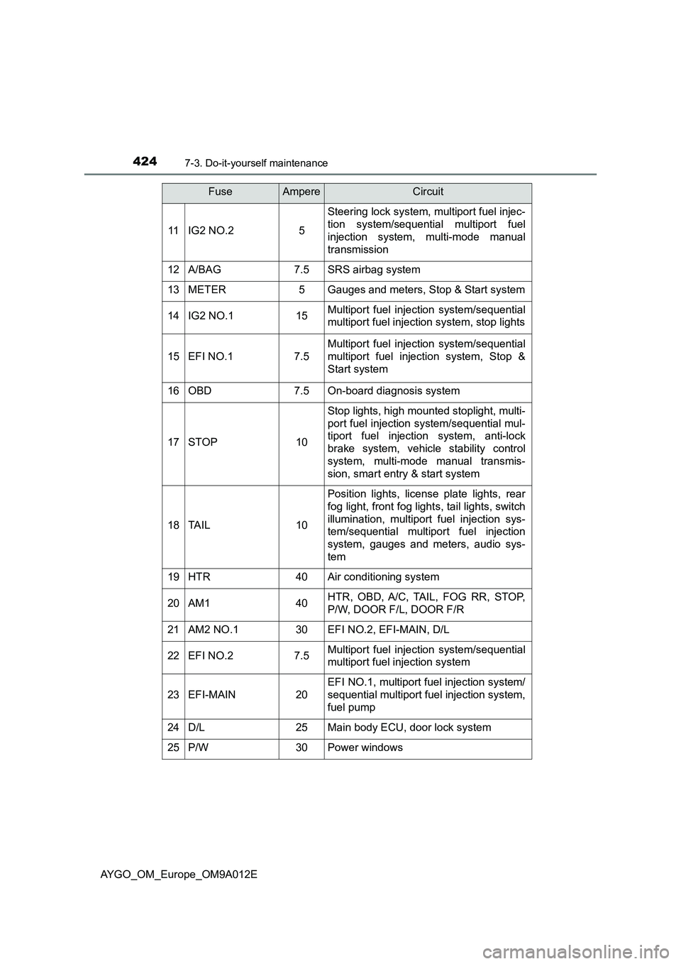
4247-3. Do-it-yourself maintenance
AYGO_OM_Europe_OM9A012E
11IG2 NO.25
Steering lock system, multiport fuel injec-
tion system/sequential multiport fuel
injection system, multi-mode manual
transmission
12A/BAG7.5SRS airbag system
13METER5Gauges and meters, Stop & Start system
14IG2 NO.115Multiport fuel injection system/sequential
multiport fuel injection system, stop lights
15EFI NO.17.5
Multiport fuel injection system/sequential
multiport fuel injection system, Stop &
Start system
16OBD7.5On-board diagnosis system
17STOP10
Stop lights, high mounted stoplight, multi-
port fuel injection system/sequential mul-
tiport fuel injection system, anti-lock
brake system, vehicle stability control
system, multi-mode manual transmis-
sion, smart entry & start system
18TA I L10
Position lights, license plate lights, rear
fog light, front fog lights, tail lights, switch
illumination, multiport fuel injection sys-
tem/sequential multiport fuel injection
system, gauges and meters, audio sys-
tem
19HTR40Air conditioning system
20AM140HTR, OBD, A/C, TAIL, FOG RR, STOP,
P/W, DOOR F/L, DOOR F/R
21AM2 NO.130EFI NO.2, EFI-MAIN, D/L
22EFI NO.27.5Multiport fuel injection system/sequential
multiport fuel injection system
23EFI-MAIN20
EFI NO.1, multiport fuel injection system/
sequential multiport fuel injection system,
fuel pump
24D/L25Main body ECU, door lock system
25P/W30Power windows
FuseAmpereCircuit
Page 430 of 546
4287-3. Do-it-yourself maintenance
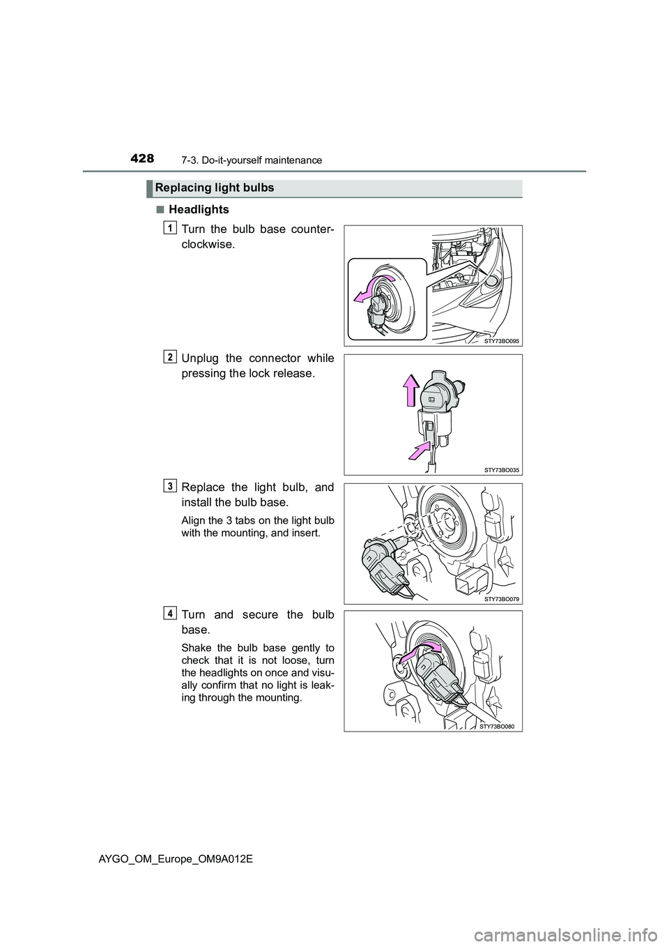
AYGO_OM_Europe_OM9A012E■
Headlights
Turn the bulb base counter-
clockwise.
Unplug the connector while
pressing the lock release.
Replace the light bulb, and
install the bulb base.
Align the 3 tabs on the light bulb
with the mounting, and insert.
Turn and secure the bulb
base.
Shake the bulb base gently to
check that it is not loose, turn
the headlights on once and visu-
ally confirm that no light is leak-
ing through the mounting.
Replacing light bulbs
Page 431 of 546
4297-3. Do-it-yourself maintenance
7
Maintenance and care
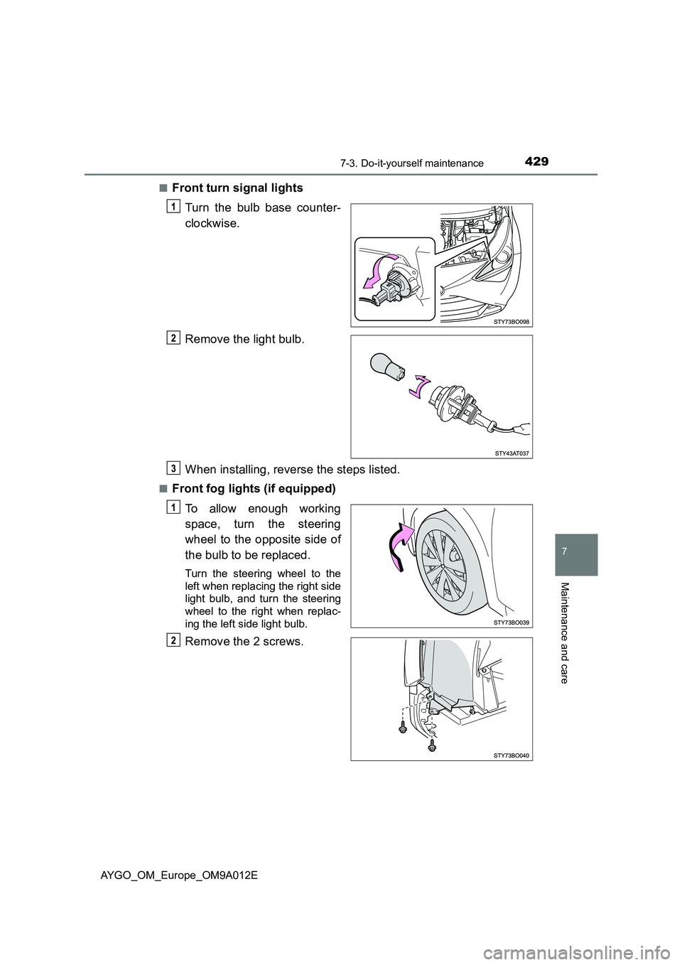
AYGO_OM_Europe_OM9A012E■
Front turn signal lights
Turn the bulb base counter-
clockwise.
Remove the light bulb.
When installing, reverse the steps listed.
■Front fog lights (if equipped)
To allow enough working
space, turn the steering
wheel to the opposite side of
the bulb to be replaced.
Turn the steering wheel to the
left when replacing the right side
light bulb, and turn the steering
wheel to the right when replac-
ing the left side light bulb.
Remove the 2 screws.
Page 432 of 546
4307-3. Do-it-yourself maintenance
AYGO_OM_Europe_OM9A012E
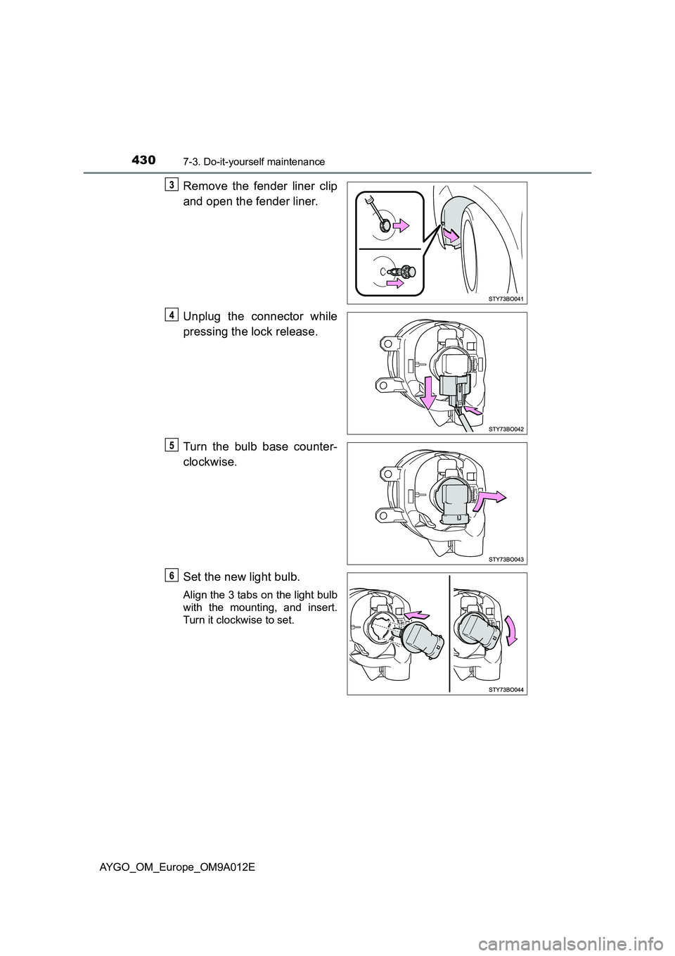
Remove the fender liner clip
and open the fender liner.
Unplug the connector while
pressing the lock release.
Turn the bulb base counter-
clockwise.
Set the new light bulb.
Align the 3 tabs on the light bulb
with the mounting, and insert.
Turn it clockwise to set.