instrument panel TOYOTA C-HR 2019 Owners Manual (in English)
[x] Cancel search | Manufacturer: TOYOTA, Model Year: 2019, Model line: C-HR, Model: TOYOTA C-HR 2019Pages: 532, PDF Size: 10.35 MB
Page 14 of 532
14Pictorial index
C-HR_OM_USA_OM10569U
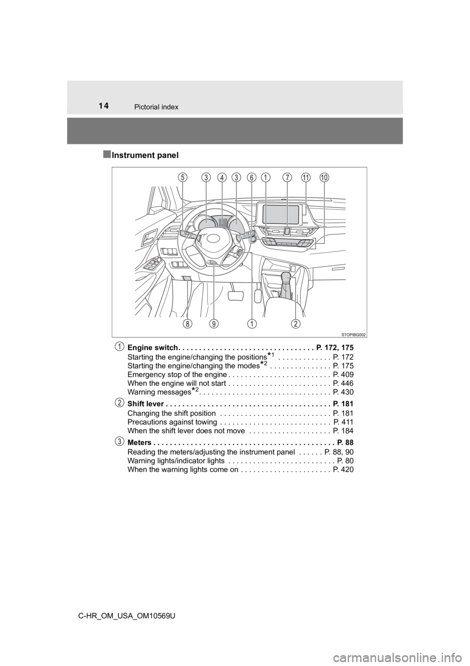
■Instrument panel
Engine switch . . . . . . . . . . . . . . . . . . . . . . . . . . . . . . . . . P. 172, 175
Starting the engine/changing the positions
*1 . . . . . . . . . . . . . P. 172
Starting the engine/changing the modes
*2 . . . . . . . . . . . . . . . P. 175
Emergency stop of the engine . . . . . . . . . . . . . . . . . . . . . . . . . P. 409
When the engine will not start . . . . . . . . . . . . . . . . . . . . . . . . . P. 446
Warning messages
*2. . . . . . . . . . . . . . . . . . . . . . . . . . . . . . . . P. 430
Shift lever . . . . . . . . . . . . . . . . . . . . . . . . . . . . . . . . . . . . . . . . P. 181
Changing the shift position . . . . . . . . . . . . . . . . . . . . . . . . . . . P. 181
Precautions against towing . . . . . . . . . . . . . . . . . . . . . . . . . . . P. 411
When the shift lever does not move . . . . . . . . . . . . . . . . . . . . P. 184
Meters . . . . . . . . . . . . . . . . . . . . . . . . . . . . . . . . . . . . . . . . . . . . P. 88
Reading the meters/adjusting the instrument panel . . . . . . P. 88, 90
Warning lights/indicator lights . . . . . . . . . . . . . . . . . . . . . . . . . . P. 80
When the warning lights come on . . . . . . . . . . . . . . . . . . . . . . P. 420
Page 16 of 532
16Pictorial index
C-HR_OM_USA_OM10569U
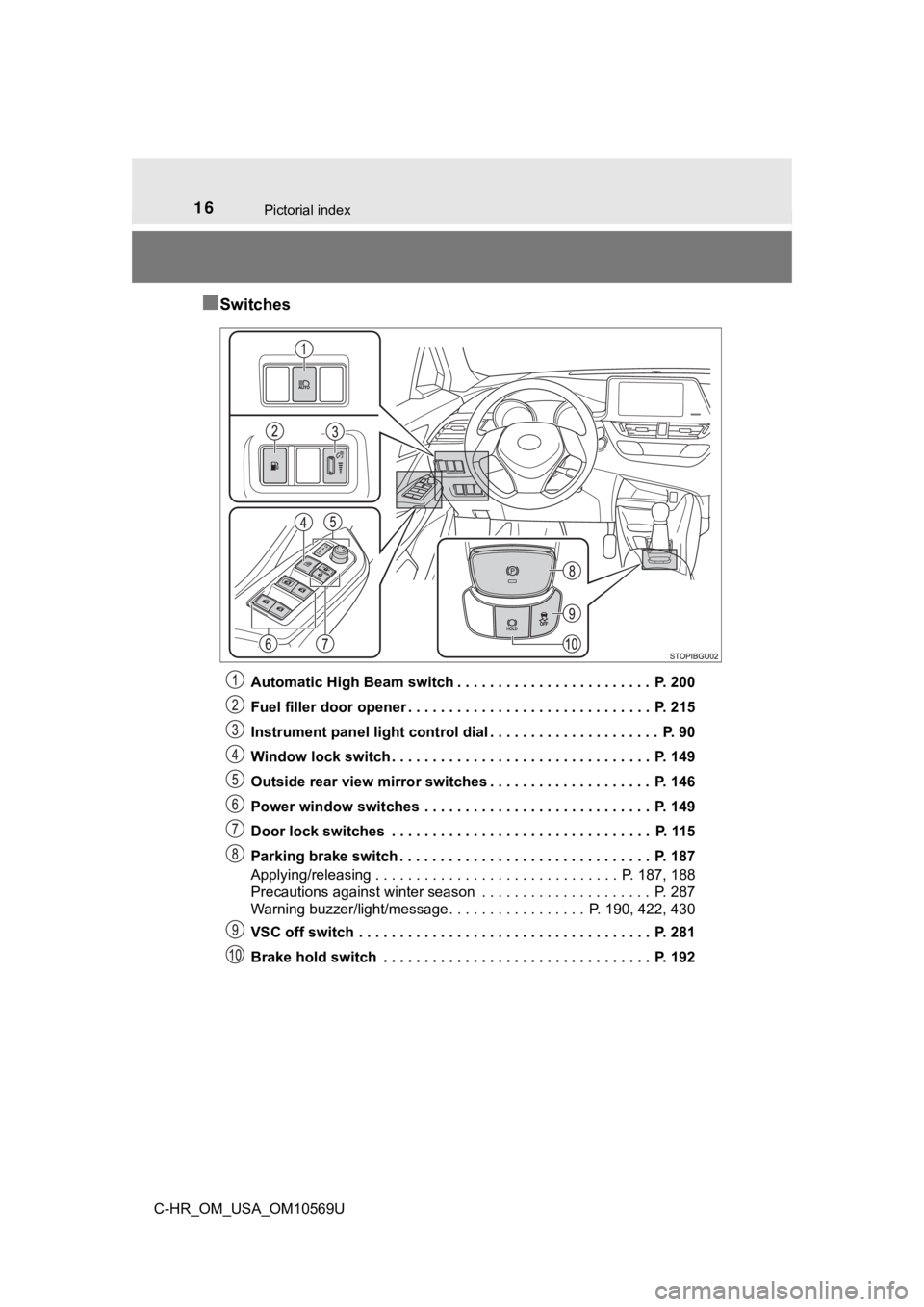
■Switches
Automatic High Beam switch . . . . . . . . . . . . . . . . . . . . . . . . P. 200
Fuel filler door opener . . . . . . . . . . . . . . . . . . . . . . . . . . . . . . P. 215
Instrument panel light control dial . . . . . . . . . . . . . . . . . . . . . P. 90
Window lock switch . . . . . . . . . . . . . . . . . . . . . . . . . . . . . . . . P. 149
Outside rear view mirror switches . . . . . . . . . . . . . . . . . . . . P. 146
Power window switches . . . . . . . . . . . . . . . . . . . . . . . . . . . . P. 149
Door lock switches . . . . . . . . . . . . . . . . . . . . . . . . . . . . . . . . P. 115
Parking brake switch . . . . . . . . . . . . . . . . . . . . . . . . . . . . . . . P. 187
Applying/releasing . . . . . . . . . . . . . . . . . . . . . . . . . . . . . . P. 187, 188
Precautions against winter season . . . . . . . . . . . . . . . . . . . . . P. 287
Warning buzzer/light/message. . . . . . . . . . . . . . . . . P. 190, 422, 430
VSC off switch . . . . . . . . . . . . . . . . . . . . . . . . . . . . . . . . . . . . P. 281
Brake hold switch . . . . . . . . . . . . . . . . . . . . . . . . . . . . . . . . . P. 192
Page 35 of 532
351-1. For safe use
1
For safety and security
C-HR_OM_USA_OM10569U
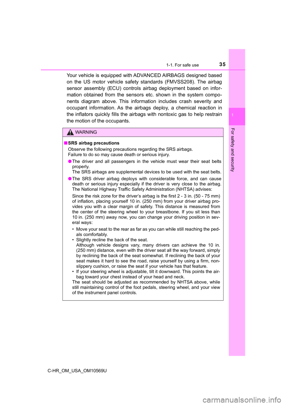
Your vehicle is equipped with ADVANCED AIRBAGS designed based
on the US motor vehicle safety standards (FMVSS208). The airbag
sensor assembly (ECU) controls airbag deployment based on infor-
mation obtained from the sensors etc. shown in the system compo -
nents diagram above. This informat ion includes crash severity and
occupant information. As the airbags deploy, a chemical reactio n in
the inflators quickly fills the airbags with nontoxic gas to he lp restrain
the motion of t he occupants.
WARNING
■SRS airbag precautions
Observe the following precautions regarding the SRS airbags.
Failure to do so may cause death or serious injury.
● The driver and all passengers in the vehicle must wear their se at belts
properly.
The SRS airbags are supplemental devices to be used with the se at belts.
● The SRS driver airbag deploys with considerable force, and can cause
death or serious injury especially if the driver is very close to the airbag.
The National Highway Traffic Safety Administration (NHTSA) advi ses:
Since the risk zone for the driver’s airbag is the first 2 - 3 in. (50 - 75 mm)
of inflation, placing yourself 10 in. (250 mm) from your driver airbag pro-
vides you with a clear margin of safety. This distance is measured from
the center of the steering wheel to your breastbone. If you sit less than
10 in. (250 mm) away now, you can change your driving position i n sev-
eral ways:
• Move your seat to the rear as far as you can while still reach ing the ped-
als comfortably.
• Slightly recline the back of the seat.
Although vehicle designs vary, many drivers can achieve the 10 in.
(250 mm) distance, even with the driver seat all the way forward , simply
by reclining the back of the seat somewhat. If reclining the ba ck of your
seat makes it hard to see the road, raise yourself by using a f irm, non-
slippery cushion, or raise the seat if your vehicle has that feature.
• If your steering wheel is adjustable, tilt it downward. This points the air-
bag toward your chest instead of your head and neck.
The seat should be adjusted as recommended by NHTSA above, whil e
still maintaining control of the foot pedals, steering wheel, and your view
of the instrument panel controls.
Page 38 of 532
381-1. For safe use
C-HR_OM_USA_OM10569U
WARNING
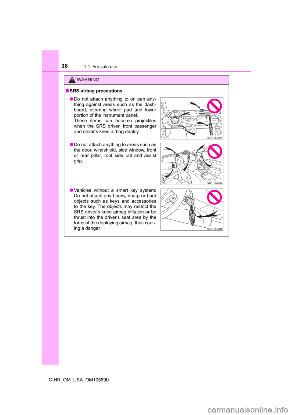
■SRS airbag precautions
● Do not attach anything to or lean any-
thing against areas such as the dash-
board, steering wheel pad and lower
portion of the instrument panel.
These items can become projectiles
when the SRS driver, front passenger
and driver’s knee airbag deploy.
● Do not attach anything to areas such as
the door, windshield, side window, front
or rear pillar, roof side rail and assist
grip.
● Vehicles without a smart key system:
Do not attach any heavy, sharp or hard
objects such as keys and accessories
to the key. The objects may restrict the
SRS driver’s knee airbag inflation or be
thrust into the driver's seat area by the
force of the deploying airbag, thus caus-
ing a danger.
Page 40 of 532

401-1. For safe use
C-HR_OM_USA_OM10569U
WARNING
■Modification and disposal of SRS airbag system components
Do not dispose of your vehicle or perform any of the following modifications
without consulting your Toyota dealer. The SRS airbags may malfunction or
deploy (inflate) accidentally, causing death or serious injury.
● Installation, removal, disassembly and repair of the SRS airbag s
● Repairs, modifications, removal or replacement of the steering wheel,
instrument panel, dashboard, seats or seat upholstery, front, s ide and rear
pillars or roof side rails or front door panels, trims and spea kers
● Modifications to the front door panel (such as making a hole in it)
● Repairs or modifications of the front fender, front bumper, or side of the
occupant compartment
● Installation of a grille guard (bull bars, kangaroo bar, etc.), snow plows,
winches or roof luggage carrier
● Modifications to the vehicle’s suspension system
● Installation of electronic devices such as mobile two-way radio s and CD
players
● Modifications to your vehicle for a person with a physical disa bility
Page 44 of 532
441-1. For safe use
C-HR_OM_USA_OM10569U■
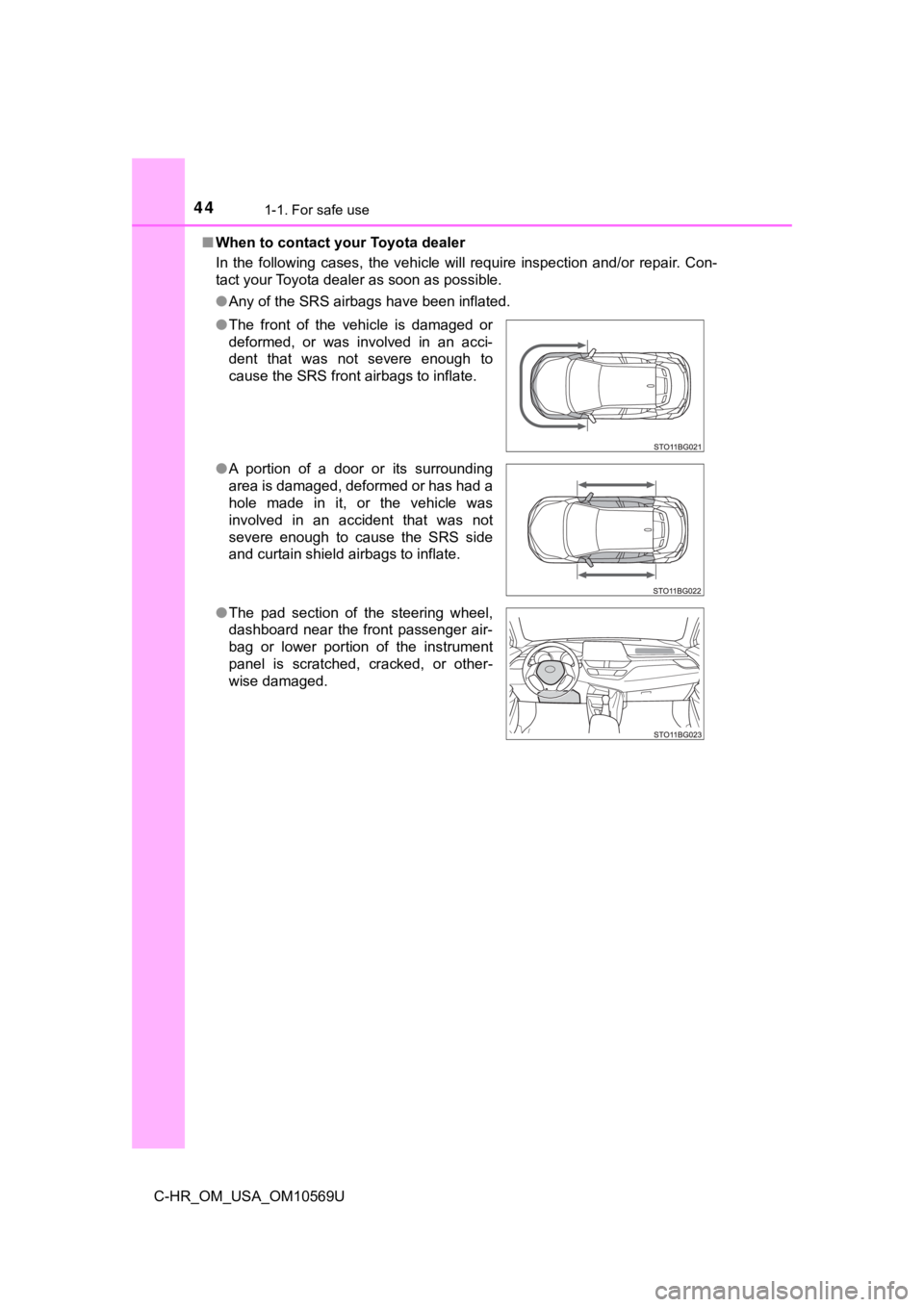
When to contact your Toyota dealer
In the following cases, the vehicle will require inspection and/or repair. Con-
tact your Toyota dealer as soon as possible.
●Any of the SRS airbags have been inflated.
● The front of the vehicle is damaged or
deformed, or was involved in an acci-
dent that was not severe enough to
cause the SRS front airbags to inflate.
● A portion of a door or its surrounding
area is damaged, deformed or has had a
hole made in it, or the vehicle was
involved in an accident that was not
severe enough to cause the SRS side
and curtain shield airbags to inflate.
● The pad section of the steering wheel,
dashboard near the front passenger air-
bag or lower portion of the instrument
panel is scratched, cracked, or other-
wise damaged.
Page 80 of 532

802. Instrument cluster
C-HR_OM_USA_OM10569U
Warning lights and indicators
The units used on the meters and some indicators may differ depending on
the target region.
The warning lights and indicators on the instrument cluster and
center panel inform the driver of the status of the vehicle’s vari-
ous systems.
For the purpose of explanation, t he following illustration dis-
plays all warning lights a nd indicators illuminated.
Page 82 of 532
822. Instrument cluster
C-HR_OM_USA_OM10569U
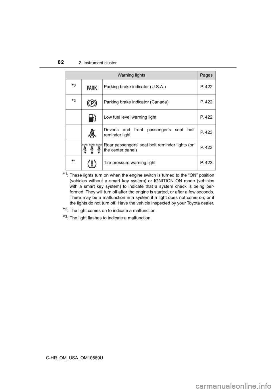
*1: These lights turn on when the engine switch is turned to the “ON” position
(vehicles without a smart key system) or IGNITION ON mode (vehi cles
with a smart key system) to indicate that a system check is bei ng per-
formed. They will turn off after the engine is started, or after a few seconds.
There may be a malfunction in a system if a light does not come on, or if
the lights do not turn off. Have the vehicle inspected by your Toyota dealer.
*2: The light comes on to indicate a malfunction.
*3: The light flashes to indicate a malfunction.
*3Parking brake indicator (U.S.A.)P. 422
*3Parking brake indicator (Canada)P. 422
Low fuel level warning lightP. 422
Driver’s and front passenger’s seat belt
reminder light P. 423
Rear passengers’ seat belt reminder lights (on
the center panel)
P. 423
*1Tire pressure warning light
P. 423
Warning lightsPages
Page 83 of 532
832. Instrument cluster
2
Instrument cluster
C-HR_OM_USA_OM10569U
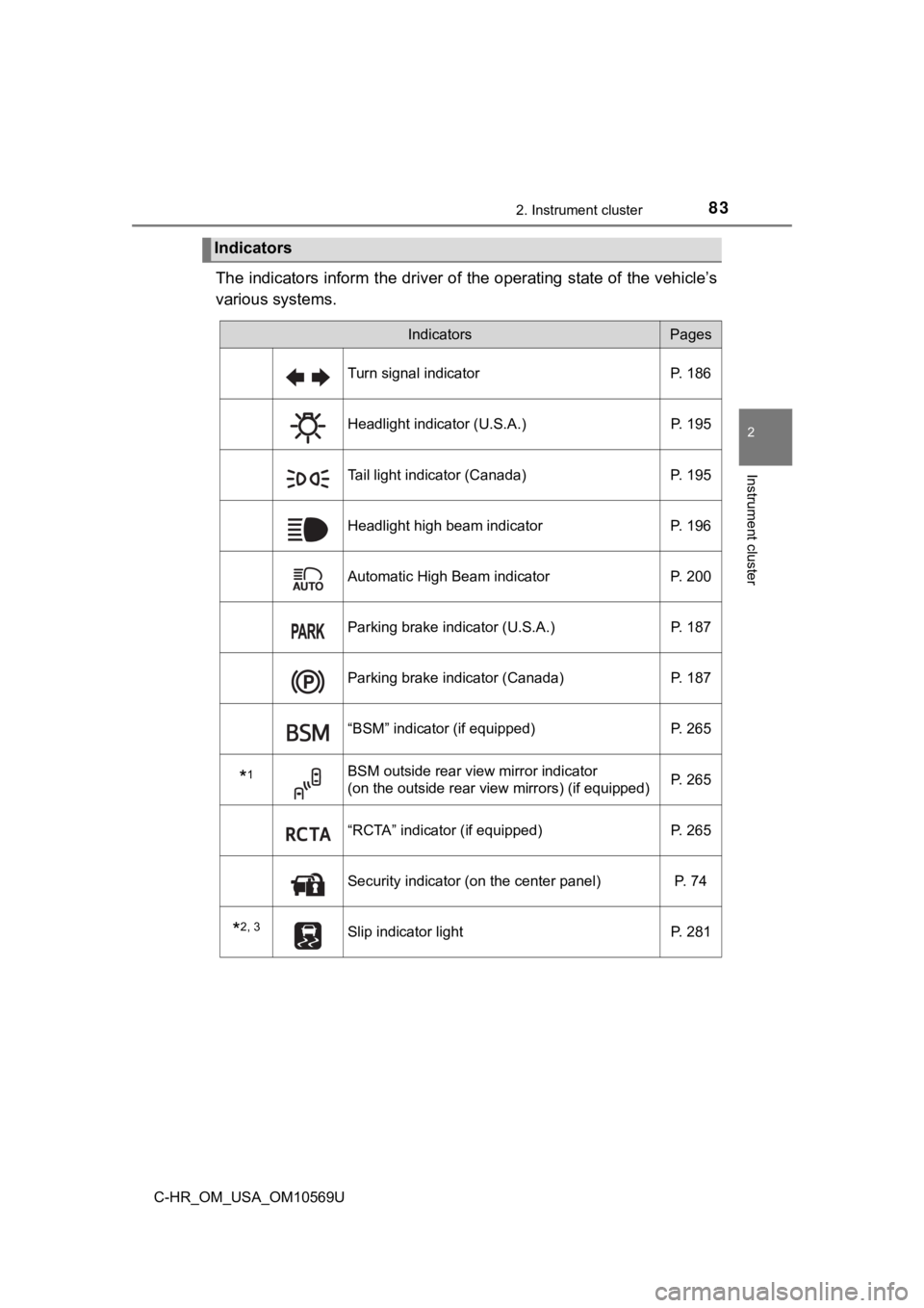
The indicators inform the driver of the operating state of the vehicle’s
various systems.
Indicators
IndicatorsPages
Turn signal indicator P. 186
Headlight indicator (U.S.A.) P. 195
Tail light indicator (Canada)P. 195
Headlight high beam indicatorP. 196
Automatic High Beam indicator P. 200
Parking brake indicator (U.S.A.) P. 187
Parking brake indicator (Canada)P. 187
“BSM” indicator (if equipped)P. 265
*1BSM outside rear view mirror indicator
(on the outside rear view mirrors) (if equipped)P. 265
“RCTA” indicator (if equipped)
P. 265
Security indicator (on the center panel) P. 74
*2, 3Slip indicator lightP. 281
Page 84 of 532
842. Instrument cluster
C-HR_OM_USA_OM10569U
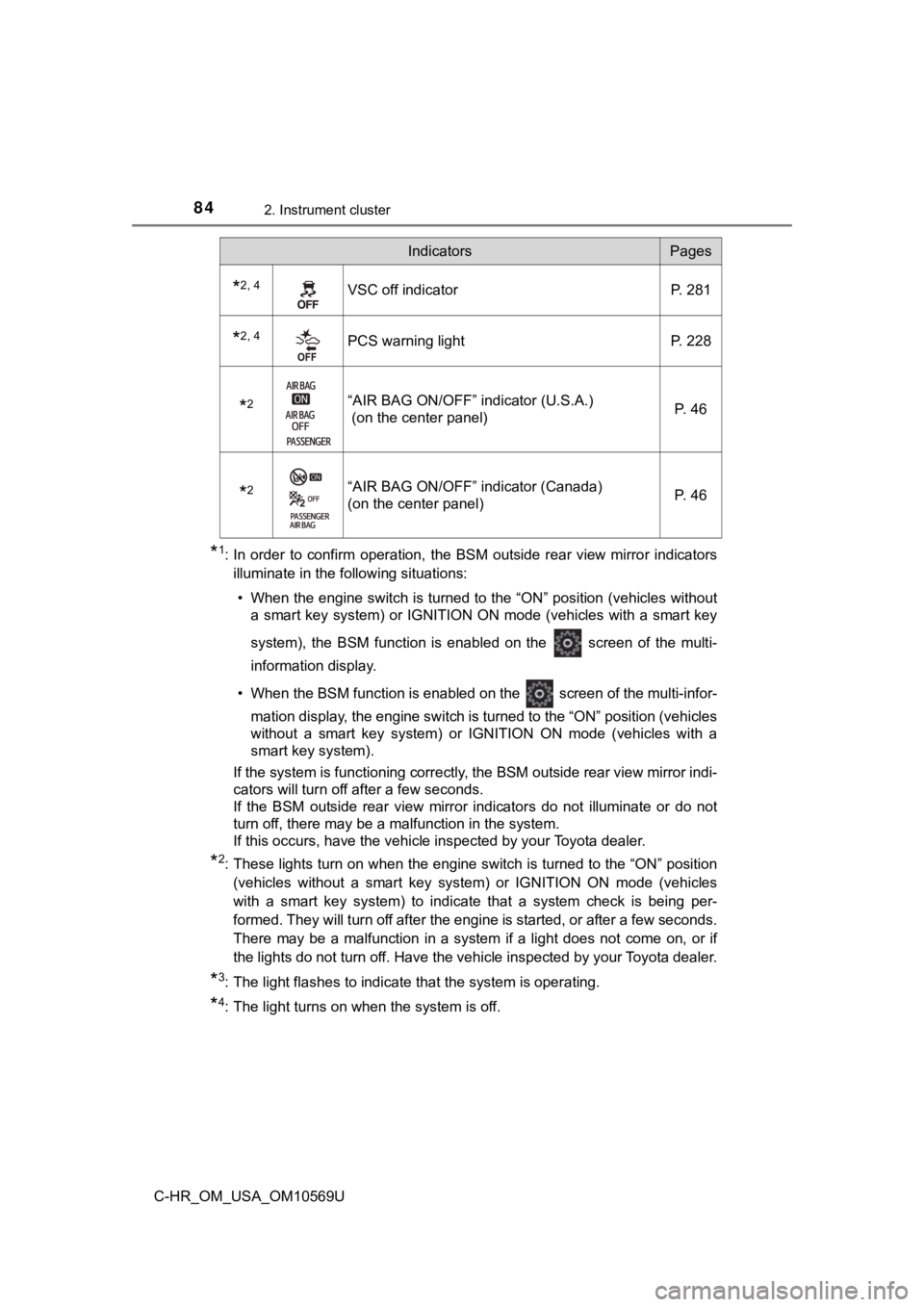
*1: In order to confirm operation, the BSM outside rear view mirror indicators
illuminate in the following situations:
• When the engine switch is turned to the “ON” position (vehicles without a smart key system) or IGNITION ON mode (vehicles with a smart key
system), the BSM function is enabled on the screen of the mult i-
information display.
• When the BSM function is enabled on the screen of the multi-i nfor-
mation display, the engine switch is turned to the “ON” positio n (vehicles
without a smart key system) or IGNITION ON mode (vehicles with a
smart key system).
If the system is functioning correctly, the BSM outside rear vi ew mirror indi-
cators will turn off after a few seconds.
If the BSM outside rear view mirror indicators do not illuminate or do not
turn off, there may be a malfunction in the system.
If this occurs, have the vehicle inspected by your Toyota deale r.
*2: These lights turn on when the engine switch is turned to the “ ON” position
(vehicles without a smart key system) or IGNITION ON mode (vehi cles
with a smart key system) to indicate that a system check is bei ng per-
formed. They will turn off after the engine is started, or after a few seconds.
There may be a malfunction in a system if a light does not come on, or if
the lights do not turn off. Have the vehicle inspected by your Toyota dealer.
*3: The light flashes to indicate that the system is operating.
*4: The light turns on when the system is off.
*2, 4VSC off indicatorP. 281
*2, 4PCS warning lightP. 228
*2“AIR BAG ON/OFF” indicator (U.S.A.)
(on the center panel) P. 46
*2“AIR BAG ON/OFF” indicator (Canada)
(on the center panel)P. 46
IndicatorsPages