TOYOTA C_HR HYBRID 2017 Manual Online
Manufacturer: TOYOTA, Model Year: 2017, Model line: C_HR HYBRID, Model: TOYOTA C_HR HYBRID 2017Pages: 712, PDF Size: 49.31 MB
Page 81 of 712
811-2. Child safety
1
For safety and security
C-HR_HV_OM_Europe_OM10538E
Key of letters inserted in the above table:
X: Not suitable seat position for ISOFIX child restraint systems in
this mass group and/or size class.
IUF: Suitable for ISOFIX forward-facing child restraint systems of “uni-
versal” category approved for use in this mass group.
IL: Suitable for ISOFIX child restraint systems of the categories for
“specific vehicles”, “restricted”, or “semi-universal” approved for
use in this mass group.
*: If the head restraint interferes with your child restraint system, and the
head restraint can be removed, remove the head restraint.
Otherwise, put the head restraint in the upper most position.
When securing some types of child restraint systems in rear seat, it
may not be possible to properly use the seat belts in positions next
to the child restraint without interfering with it or affecting seat belt
effectiveness. Be sure your seat belt fits snugly across your shoul-
der and low on your hips. If it does not, or if it interferes with the
child restraint, move to a different position. Failure to do so may
result in death or serious injury.
The child restraint systems mentioned in the table may not be avail-
able outside the EU area.
● When installing a child restraint in the rear seats, adjust the front
seat so that it does not interfere with the child or child restraint
system.
Page 82 of 712
821-2. Child safety
C-HR_HV_OM_Europe_OM10538E
■i-Size child restraint systems fastened with ISOFIX (ECE
R129) - Compatibility table
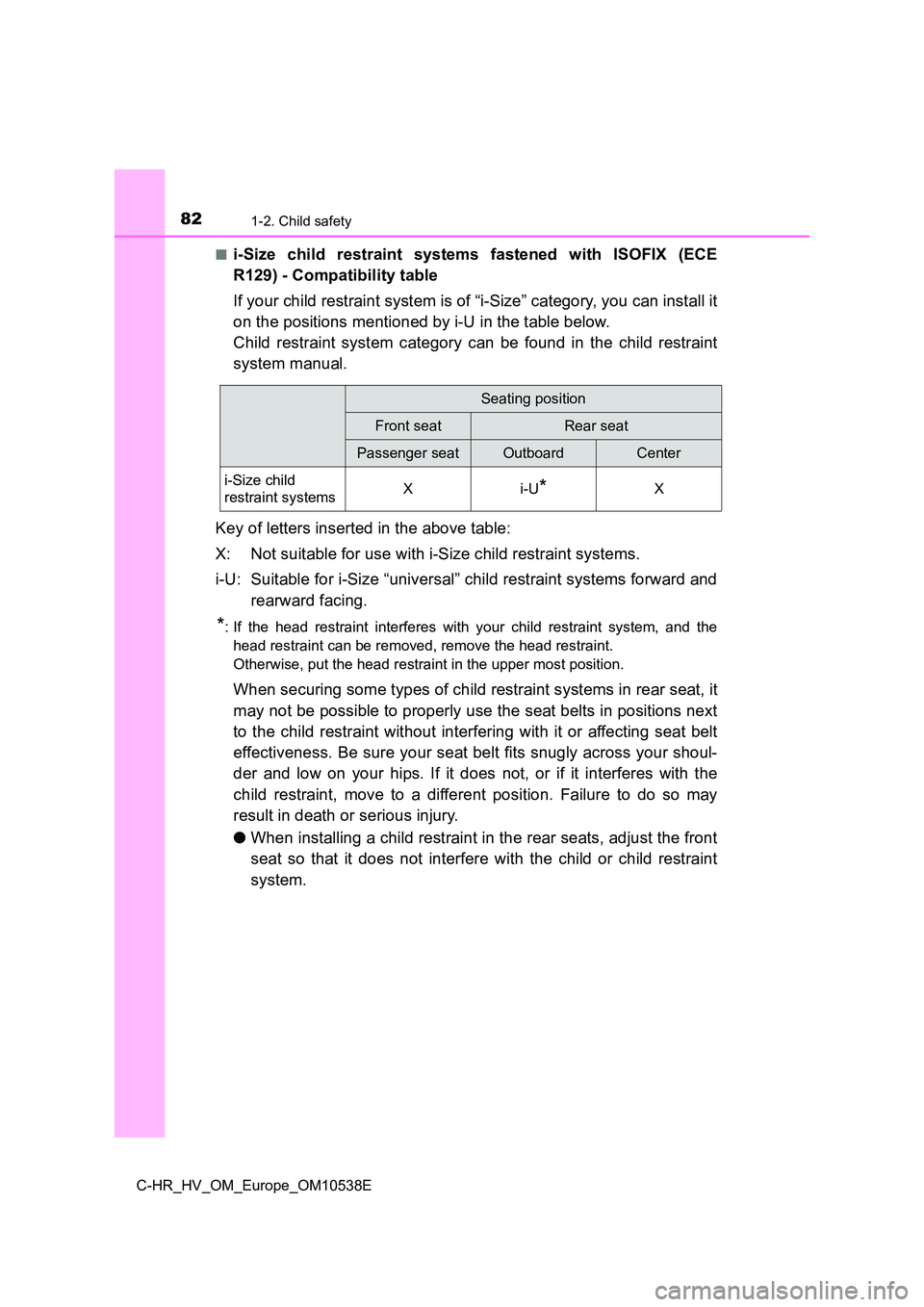
If your child restraint system is of “i-Size” category, you can install it
on the positions mentioned by i-U in the table below.
Child restraint system category can be found in the child restraint
system manual.
Key of letters inserted in the above table:
X: Not suitable for use with i-Size child restraint systems.
i-U: Suitable for i-Size “universal” child restraint systems forward and
rearward facing.
*: If the head restraint interferes with your child restraint system, and the
head restraint can be removed, remove the head restraint.
Otherwise, put the head restraint in the upper most position.
When securing some types of child restraint systems in rear seat, it
may not be possible to properly use the seat belts in positions next
to the child restraint without interfering with it or affecting seat belt
effectiveness. Be sure your seat belt fits snugly across your shoul-
der and low on your hips. If it does not, or if it interferes with the
child restraint, move to a different position. Failure to do so may
result in death or serious injury.
● When installing a child restraint in the rear seats, adjust the front
seat so that it does not interfere with the child or child restraint
system.
Seating position
Front seatRear seat
Passenger seatOutboardCenter
i-Size child
restraint systemsXi-U*X
Page 83 of 712
831-2. Child safety
1
For safety and security
C-HR_HV_OM_Europe_OM10538E
■Installation with ISOFIX rigid anchor (ISOFIX child restraint
system)
Install the child restraint system in accordance to the operation
manual enclosed with the child restraint system.
If the head restraint interferes with the child restraint system
installation and the head restraint can be removed, remove the
head restraint. Otherwise, put the head restraint in the upper
most position. ( P. 182)
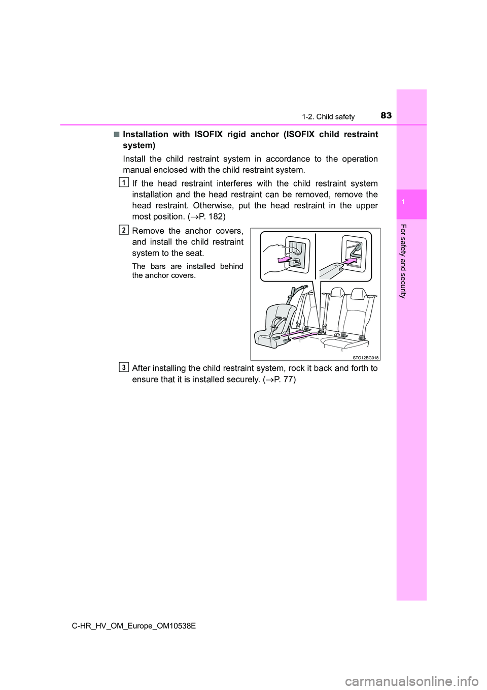
Remove the anchor covers,
and install the child restraint
system to the seat.
The bars are installed behind
the anchor covers.
After installing the child restraint system, rock it back and forth to
ensure that it is installed securely. ( P. 7 7 )
1
2
3
Page 84 of 712
841-2. Child safety
C-HR_HV_OM_Europe_OM10538E
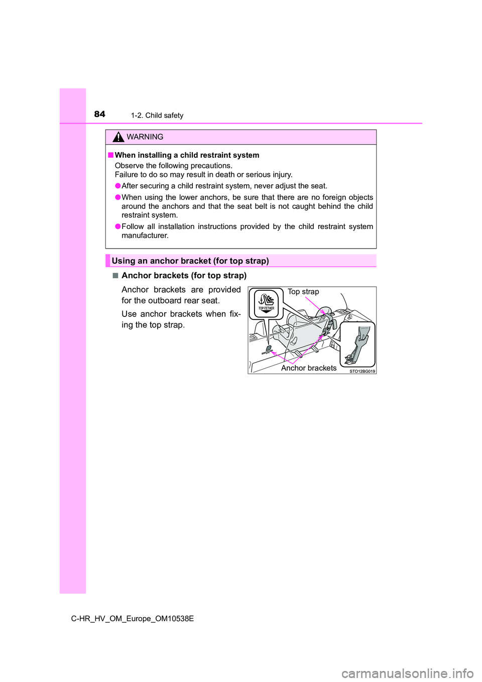
■Anchor brackets (for top strap)
Anchor brackets are provided
for the outboard rear seat.
Use anchor brackets when fix-
ing the top strap.
WARNING
■ When installing a child restraint system
Observe the following precautions.
Failure to do so may result in death or serious injury.
● After securing a child restraint system, never adjust the seat.
● When using the lower anchors, be sure that there are no foreign objects
around the anchors and that the seat belt is not caught behind the child
restraint system.
● Follow all installation instructions provided by the child restraint system
manufacturer.
Using an anchor bracket (for top strap)
Anchor brackets
Top strap
Page 85 of 712
851-2. Child safety
1
For safety and security
C-HR_HV_OM_Europe_OM10538E
■Fixing the top strap to the anchor bracket
Install the child restraint system in accordance to the operation
manual enclosed with the child restraint system.
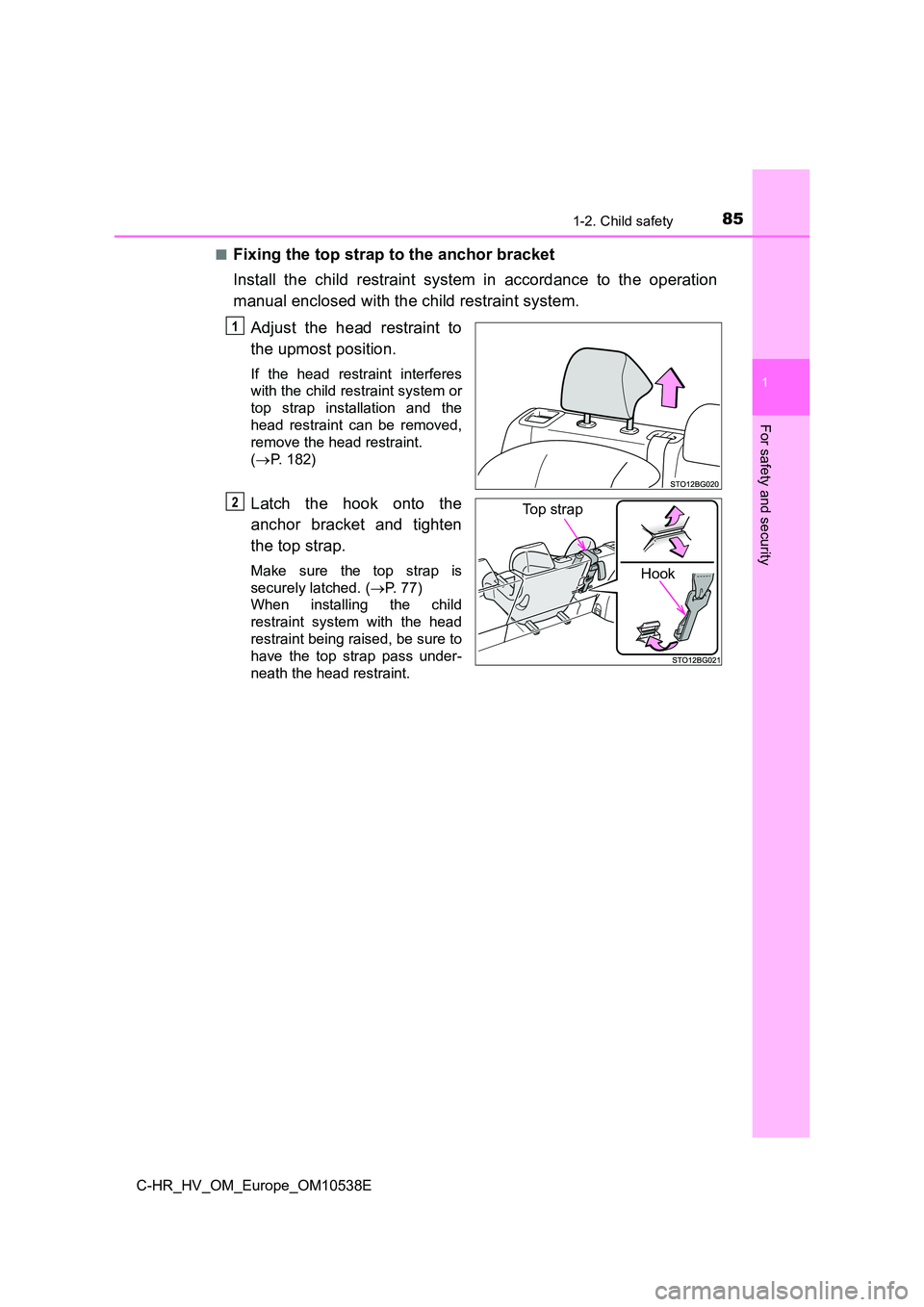
Adjust the head restraint to
the upmost position.
If the head restraint interferes
with the child restraint system or
top strap installation and the
head restraint can be removed,
remove the head restraint.
( P. 182)
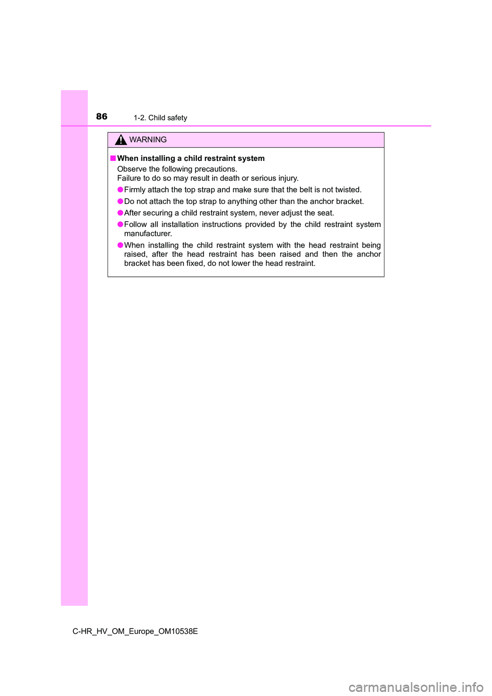
Latch the hook onto the
anchor bracket and tighten
the top strap.
Make sure the top strap is
securely latched. ( P. 77)
When installing the child
restraint system with the head
restraint being raised, be sure to
have the top strap pass under-
neath the head restraint.
1
Hook
Top strap 2
Page 86 of 712
861-2. Child safety
C-HR_HV_OM_Europe_OM10538E
WARNING
■When installing a child restraint system
Observe the following precautions.
Failure to do so may result in death or serious injury.
● Firmly attach the top strap and make sure that the belt is not twisted.
● Do not attach the top strap to anything other than the anchor bracket.
● After securing a child restraint system, never adjust the seat.
● Follow all installation instructions provided by the child restraint system
manufacturer.
● When installing the child restraint system with the head restraint being
raised, after the head restraint has been raised and then the anchor
bracket has been fixed, do not lower the head restraint.
Page 87 of 712
87
1
1-3. Hybrid system
For safety and security
C-HR_HV_OM_Europe_OM10538E
Hybrid system features
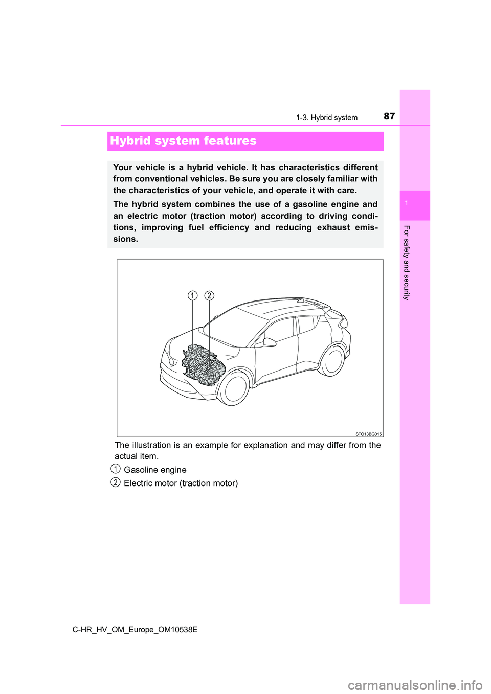
The illustration is an example for explanation and may differ from the
actual item.
Gasoline engine
Electric motor (traction motor)
Your vehicle is a hybrid vehicle. It has characteristics different
from conventional vehicles. Be sure you are closely familiar with
the characteristics of your vehicle, and operate it with care.
The hybrid system combines the use of a gasoline engine and
an electric motor (traction motor) according to driving condi-
tions, improving fuel efficiency and reducing exhaust emis-
sions.
1
2
Page 88 of 712
881-3. Hybrid system
C-HR_HV_OM_Europe_OM10538E
◆When stopped/during start off
The gasoline engine stops* when the vehicle is stopped. During
start off, the electric motor (traction motor) drives the vehicle. At
slow speeds or when traveling down a gentle slope, the engine is
stopped* and the electric motor (traction motor) is used.
When shift lever is in N, the hybrid battery (traction battery) is not
being charged.
*: When the hybrid battery (traction battery) requires charging or the engine
is warming up, etc., the gasoline engine will not automatically stop.
( P. 89)
◆During normal driving
The gasoline engine is predominantly used. The electric motor
(traction motor) charges the hybrid battery (traction battery) as nec-
essary.
◆When accelerating sharply
When the accelerator pedal is depressed heavily, the power of the
hybrid battery (traction battery) is added to that of the gasoline
engine via the electric motor (traction motor).
◆When braking (regenerative braking)
The wheels operate the electric motor (traction motor) as a power
generator, and the hybrid battery (traction battery) is charged.
Page 89 of 712
891-3. Hybrid system
1
For safety and security
C-HR_HV_OM_Europe_OM10538E
■Regenerative braking
In the following situations, kinetic ener gy is converted to electric energy and
deceleration force can be obtained in c onjunction with the recharging of the
hybrid battery (traction battery).
● The accelerator pedal is released while driving with the shift lever in D or B.
● The brake pedal is depressed while driving with the shift lever in D or B.
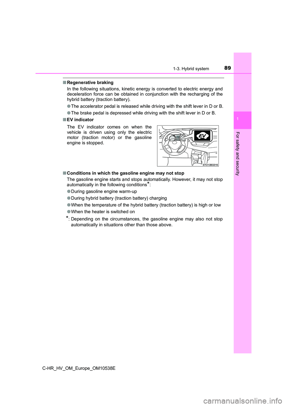
■ EV indicator
■ Conditions in which the gasoline engine may not stop
The gasoline engine starts and stops automatically. However, it may not stop
automatically in the following conditions*:
● During gasoline engine warm-up
● During hybrid battery (traction battery) charging
● When the temperature of the hybrid battery (traction battery) is high or low
● When the heater is switched on
*: Depending on the circumstances, the gasoline engine may also not stop
automatically in situations other than those above.
The EV indicator comes on when the
vehicle is driven using only the electric
motor (traction motor) or the gasoline
engine is stopped.
Page 90 of 712
901-3. Hybrid system
C-HR_HV_OM_Europe_OM10538E
■ Charging the hybrid battery (traction battery)
As the gasoline engine charges the hybrid battery (traction battery), the bat-
tery does not need to be charged from an outside source. However, if the
vehicle is left parked for a long time the hybrid battery (traction battery) will
slowly discharge. For this reason, be sure to drive the vehicle at least once
every few months for at least 30 minutes or 16 km (10 miles). If the hybrid
battery (traction battery) becomes fully discharged and you are unable to start
the hybrid system, contact any authorized Toyota retailer or Toyota authorized
repairer, or any reliable repairer.
■ Charging the 12-volt battery
P. 653
■ After the 12-volt battery has discharged or when the terminal has been
removed and installed during exchange, etc.
The gasoline engine may not stop even if the vehicle is being driven by the
hybrid battery (traction battery). If this continues for a few days, contact any
authorized Toyota retailer or Toyota authorized repairer, or any reliable
repairer.