trouble shooting TOYOTA CAMRY 2000 Service Repair Manual
[x] Cancel search | Manufacturer: TOYOTA, Model Year: 2000, Model line: CAMRY, Model: TOYOTA CAMRY 2000Pages: 4770, PDF Size: 86.41 MB
Page 72 of 4770
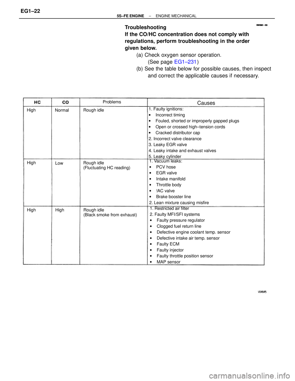
Troubleshooting
If the CO/HC concentration does not comply with
regulations, perform troubleshooting in the order
given below.
(a) Check oxygen sensor operation.
(See page EG1±231)
(b) See the table below for possible causes, then inspect
and correct the applicable causes if necessary.
1. Faulty ignitions:
wIncorrect timing
wFouled, shorted or improperly gapped plugs
wOpen or crossed high±tension cords
wCracked distributor cap
2. Incorrect valve clearance
3. Leaky EGR valve
4. Leaky intake and exhaust valves
5. Leaky cylinder
1. Restricted air filter
2. Faulty MFI/SFI systems
wFaulty pressure regulator
wClogged fuel return line
wDefective engine coolant temp. sensor
wDefective intake air temp. sensor
wFaulty ECM
wFaulty injector
wFaulty throttle position sensor
wMAP sensor 1. Vacuum leaks:
wPCV hose
wEGR valve
wIntake manifold
wThrottle body
w!AC valve
wBrake booster line
2. Lean mixture causing misfire
Rough idle
(Black smoke from exhaust) Rough idle
(Fluctuating HC reading) Rough idleProblems
Causes
Normal
High High High
HighLow
± 5S±FE ENGINEENGINE MECHANICALEG1±22
Page 223 of 4770
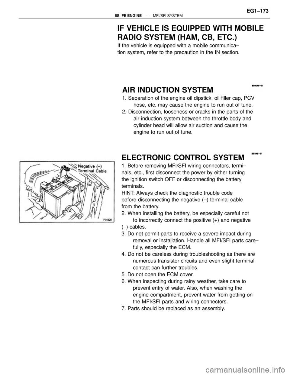
ELECTRONIC CONTROL SYSTEM
1. Before removing MFI/SFI wiring connectors, termi±
nals, etc., first disconnect the power by either turning
the ignition switch OFF or disconnecting the battery
terminals.
HINT: Always check the diagnostic trouble code
before disconnecting the negative (±) terminal cable
from the battery.
2. When installing the battery, be especially careful not
to incorrectly connect the positive (+) and negative
(±) cables.
3. Do not permit parts to receive a severe impact during
removal or installation. Handle all MFI/SFI parts care±
fully, especially the ECM.
4. Do not be careless during troubleshooting as there are
numerous transistor circuits and even slight terminal
contact can further troubles.
5. Do not open the ECM cover.
6. When inspecting during rainy weather, take care to
prevent entry of water. Also, when washing the
engine compartment, prevent water from getting on
the MFI/SFI parts and wiring connectors.
7. Parts should be replaced as an assembly.
AIR INDUCTION SYSTEM
1. Separation of the engine oil dipstick, oil filler cap, PCV
hose, etc. may cause the engine to run out of tune.
2. Disconnection, looseness or cracks in the parts of the
air induction system between the throttle body and
cylinder head will allow air suction and cause the
engine to run out of tune.
IF VEHICLE IS EQUIPPED WITH MOBILE
RADIO SYSTEM (HAM, CB, ETC.)
If the vehicle is equipped with a mobile communica±
tion system, refer to the precaution in the IN section.
± 5S±FE ENGINEMFI/SFI SYSTEMEG1±173
Page 341 of 4770

5S±FE ENGINE TROUBLESHOOTING
± 5S±FE ENGINEEG1±291
Page 342 of 4770

HOW TO PROCEED WITH TROUBLESHOOTING
The Engine Control System broadly consists of the sensors, Engine Control Module (ECM) and actuators.
The ECM receives signals from various sensors, judges the operating conditions and determines the
optimum injection duration, timing, ignition timing and idle speed.
In general, the Engine Control System is considered to be a very intricate system to troubleshoot. But, the
fact is that if you proceed to inspect the circuit one by one following the procedures directed in this manu-
al, troubleshooting of this system is not complex.
This section explains the most ideal method of troubleshooting and tells how to carry out the necessary
repairs.
1. CUSTOMER PROBLEM ANALYSIS
Using the customer problem analysis check sheet for reference, ask the customer in as much details
as possible about the problem.
2. CHECK AND CLEAR DIAGNOSTIC TROUBLE CODE (PRECHECK)
Before confirming the problem symptom, first check the diagnostic trouble code and make a note of
any malfunction code which is output, then clear the code.
HINT: Output of the malfunction code indicates that there is a malfunction in the circuit indicated.
However, it does not indicate whether the malfunction is still occurring or occurred in the past and
returned to normal. In order to determine this, the problem sym toms should be confirmed in step 4
first and the diagnostic trouble code be rechecked in step [6].
Accordingly, if troubleshooting is begun based on the malfunction code only in diagnostic trouble
code check in step [2], it could result in a misdiagnosis, leading to troubleshooting of circuits which
are normal and making it more difficult to locate the cause of the problem.
3. SETTING THE TEST MODE DIAGNOSIS, [4] PROBLEM SYMPTOM CONFIRMATION,
[5] SYMPTOM SIMULATION
In order to find out the trouble more quickly, set the diagnosis check in test mode and with higher
sensing ability of the ECM, confirm the problem symptoms. If the trouble does not reappear, use the
symptom simulation method to make sure the trouble is reproduced.
6. DIAGNOSTIC TROUBLE CODE CHECK IN TEST MODE
Check the diagnostic trouble code in test mode. If the malfunction code is output, proceed to step. If the
normal code is output, proceed to step [7].
7. BASIC INSPECTION
Carry out basic inspection such as the spark check and fuel pressure check, etc.
8. DIAGNOSTIC TROUBLE CODE CHART
If the malfunction code is displayed, proceed to inspect the circuit indicated by the chart for each
code.
9. MATRIX CHART OF PROBLEM SYMPTOMS
If the normal code is displayed in the diagnosis in test mode, perform troubleshooting according to
the inspection order in the Matrix Chart of Problem Symptoms.
10. PARTS INSPECTION
When the Matrix Chart of Problem Symptoms instructs to check the parts, proceed to parts inspection
section included in this manual.
11. CIRCUIT INSPECTION
Determine if the malfunction is the sensor, actuator, wire harness, connector or the ECM.
± 5S±FE ENGINEHOW TO PROCEED WITH TROUBLESHOOTINGEG1±292
Page 343 of 4770
CHECK FOR MOMENTARY INTERRUPTION
By performing the check for momentary interruption, the place where momentary interruptions or
momentary shorts are occurring due to poor contacts can be isolated.
ADJUSTMENT, REPAIR
After the cause of the problem is located, perform adjustment or repairs by following the inspection
and replacement procedures in this manual.
CONFIRMATION TEST
After completing adjustment or repairs, confirm not only that the malfunction is eliminated, but also
conduct a test drive, etc., to make sure the entire Engine Control System is operating normally.
± 5S±FE ENGINEHOW TO PROCEED WITH TROUBLESHOOTINGEG1±293
Page 344 of 4770

Titles inside are titles of pages
in this manual, with the page number
indicated in the bottom portion.
See the indicated pages for detailed
explanations
: Diagnostic steps per±
mitting the use of the
TOYOTA hand±held
tester or TOYOTA
break±out±box. Setting the Test Mode Diagnosis
P. EG1±298 Check and clear Diagnostic Trouble Code (Pre-
check.)
Check for Momentary Interruption Malfunction does not occur.
Matrix Chart of Problem SymptomsProblem Symptom ConfirmationVehicle Brought to Workshop
Diagnostic Trouble Code Chart Diagnostic Trouble Code Check Customer Problem Analysis
Symptom Simulation
Identification of ProblemCircuit Inspection Malfunction
occurs:
Adjustment, Repair
Confirmation Test Parts InspectionMalfunction code
Basic InspectionP. EG1±297, 299
P. EG1±309 p.
EG1±310P. EG1±298
Normal codeP. EG1±295
P. EG1±327P. EG1±300
P. EG1±336P. IN±24
EndStep
± 5S±FE ENGINEHOW TO PROCEED WITH TROUBLESHOOTINGEG1±294
Page 347 of 4770
Diagnosis Inspection (Normal Mode)
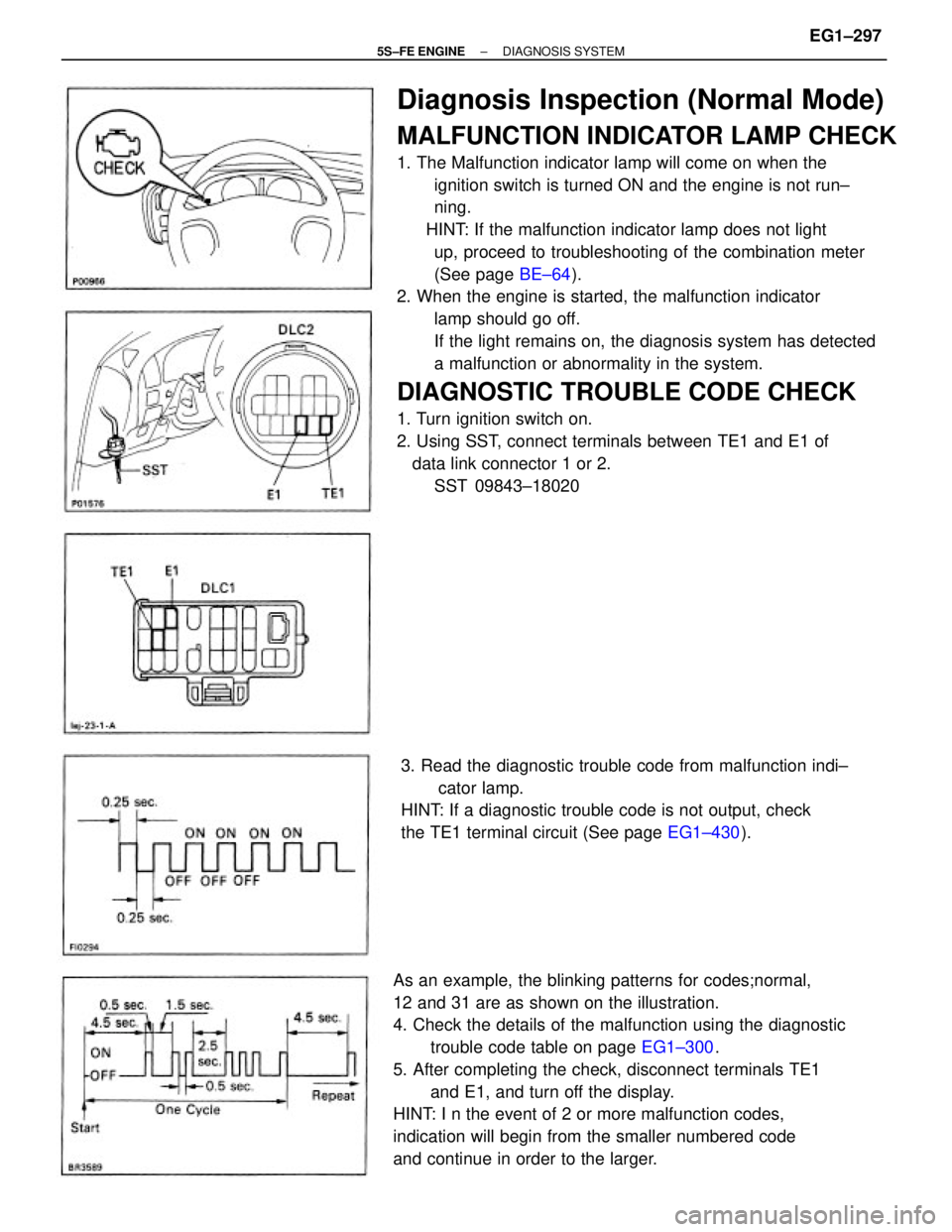
MALFUNCTION INDICATOR LAMP CHECK
1. The Malfunction indicator lamp will come on when the
ignition switch is turned ON and the engine is not run±
ning.
HINT: If the malfunction indicator lamp does not light
up, proceed to troubleshooting of the combination meter
(See page BE±64).
2. When the engine is started, the malfunction indicator
lamp should go off.
If the light remains on, the diagnosis system has detected
a malfunction or abnormality in the system.
DIAGNOSTIC TROUBLE CODE CHECK
1. Turn ignition switch on.
2. Using SST, connect terminals between TE1 and E1 of
data link connector 1 or 2.
SST 09843±18020
As an example, the blinking patterns for codes;normal,
12 and 31 are as shown on the illustration.
4. Check the details of the malfunction using the diagnostic
trouble code table on page EG1±300.
5. After completing the check, disconnect terminals TE1
and E1, and turn off the display.
HINT: I n the event of 2 or more malfunction codes,
indication will begin from the smaller numbered code
and continue in order to the larger.3. Read the diagnostic trouble code from malfunction indi±
cator lamp.
HINT: If a diagnostic trouble code is not output, check
the TE1 terminal circuit (See page EG1±430).
± 5S±FE ENGINEDIAGNOSIS SYSTEMEG1±297
Page 348 of 4770
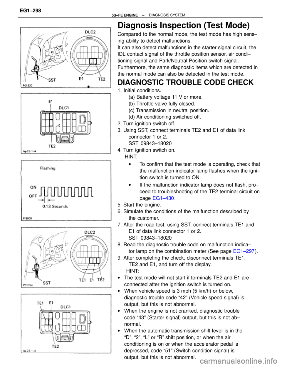
Diagnosis Inspection (Test Mode)
Compared to the normal mode, the test mode has high sens±
ing ability to detect malfunctions.
It can also detect malfunctions in the starter signal circuit, the
IDL contact signal of the throttle position sensor, air condi±
tioning signal and Park/Neutral Position switch signal.
Furthermore, the same diagnostic items which are detected in
the normal mode can also be detected in the test mode.
DIAGNOSTIC TROUBLE CODE CHECK
1. Initial conditions.
(a) Battery voltage 11 V or more.
(b) Throttle valve fully closed.
(c) Transmission in neutral position.
(d) Air conditioning switched off.
2. Turn ignition switch off.
3. Using SST, connect terminals TE2 and E1 of data link
connector 1 or 2.
SST 09843±18020
4. Turn ignition switch on.
HINT:
wTo confirm that the test mode is operating, check that
the malfunction indicator lamp flashes when the igni±
tion switch is turned to ON.
wIf the malfunction indicator lamp does not flash, pro±
ceed to troubleshooting of the TE2 terminal circuit on
page EG1±430.
5. Start the engine.
6. Simulate the conditions of the malfunction described by
the customer.
7. After the road test, using SST, connect terminals TE1 and
E1 of data link connector 1 or 2.
SST 09843±18020
8. Read the diagnostic trouble code on malfunction indica±
tor lamp on the combination meter (See page EG1±297).
9. After completing the check, disconnect terminals TE1,
TE2 and E1, and turn off the display.
HINT:
wThe test mode will not start if terminals TE2 and E1 are
connected after the ignition switch is turned on.
wWhen vehicle speed is 3 mph (5 km/h) or below,
diagnostic trouble code ª42º (Vehicle speed signal) is
output, but this is not abnormal.
wWhen the engine is not cranked, diagnostic trouble
code ª43º (Starter signal) output, but this is not ab±
normal.
wWhen the automatic transmission shift lever is in the
ªDº, ª2º, ªLº or ªRº shift position, or when the air
conditioning is on or when the accelerator pedal is
depressed, code ª51º (Switch condition signal) is
output, but this is not abnormal.
± 5S±FE ENGINE DIAGNOSIS SYSTEMEG1±298
Page 360 of 4770
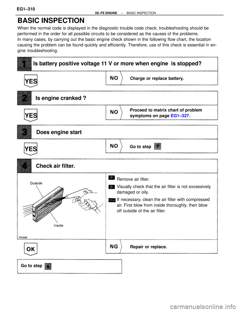
BASIC INSPECTION
When the normal code is displayed in the diagnostic trouble code check, troubleshooting should be
performed in the order for all possible circuits to be considered as the causes of the problems.
In many cases, by carrying out the basic engine check shown in the following flow chart, the location
causing the problem can be found quickly and efficiently. Therefore, use of this check is essential in en-
gine troubleshooting.
Remove air filter.
Visually check that the air filter is not excessively
damaged or oily.
If necessary, clean the air filter with compressed
air. First blow from inside thoroughly, then blow
off outside of the air filter.
Is battery positive voltage 11 V or more when engine is stopped?
Proceed to matrix chart of problem
symptoms on page EG1±327.
Is engine cranked ?
Does engine start
Charge or replace battery.
Check air filter.
Repair or replace. Go to step
Go to step
YESYES
YES
± 5S±FE ENGINEBASIC INSPECTIONEG1±310
Page 377 of 4770
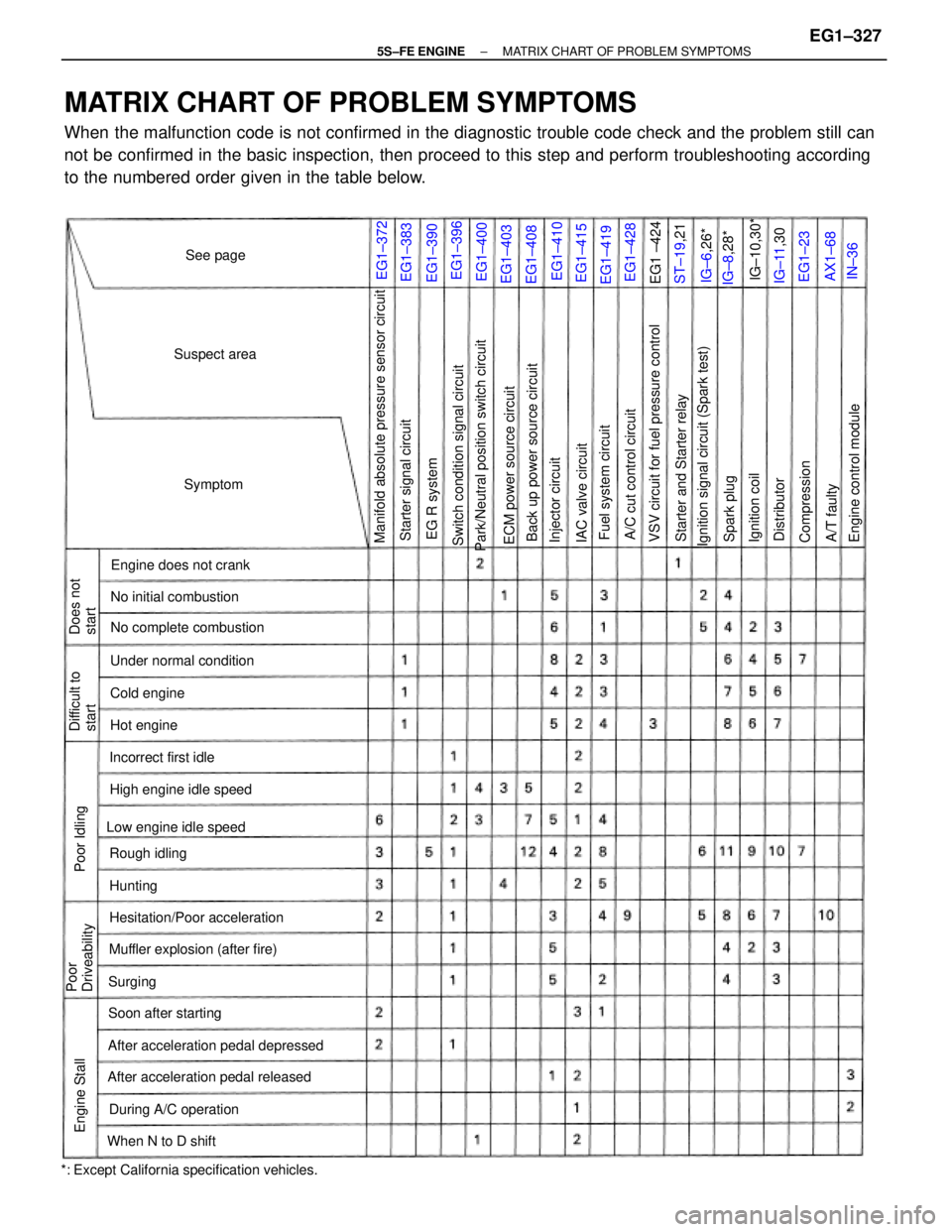
MATRIX CHART OF PROBLEM SYMPTOMS
When the malfunction code is not confirmed in the diagnostic trouble code check and the problem still can
not be confirmed in the basic inspection, then proceed to this step and perform troubleshooting according
to the numbered order given in the table below.
*: Except California specification vehicles.
Park/Neutral position switch circuitManifold absolute pressure sensor circuit
VSV circuit for fuel pressure control
Ignition signal circuit (Spark test)
After acceleration pedal depressed
After acceleration pedal released
Switch condition signal circuit
Muffler explosion (after fire)No initial combustion
Back up power source circuit
Hesitation/Poor accelerationNo complete combustion
ECM power source circuit
Starter and Starter relay
Engine control module
High engine idle speed
Low engine idle speedUnder normal condition
During A/C operationEngine does not crank
A/C cut control circuit Starter signal circuit
Soon after starting
Fuel system circuit
When N to D shiftIncorrect first idle
Poor
Driveability
IAC valve circuit Difficult to
start
Injector circuit
Rough idling
Does not
start
Compression
Suspect area
Cold engine
Ignition coil Engine Stall
EG R system
Hot engine
Poor Idling
Spark plug
A/T faultylG±10,30*
IG±11,30 Distributor
Symptom
ST±19,21
See page
IG±8,28* IG±6,26*
Hunting
Surging
EG1±400
EG1±410 EG1±390
EG1±403
EG1±408
EG1±415
EG1±419EG1±383EG1±372
EG1±428EG1±396
EG1 ±424
AX1±68 EG1±23
IN±36
± 5S±FE ENGINEMATRIX CHART OF PROBLEM SYMPTOMSEG1±327