trouble shooting TOYOTA CAMRY 2000 Service User Guide
[x] Cancel search | Manufacturer: TOYOTA, Model Year: 2000, Model line: CAMRY, Model: TOYOTA CAMRY 2000Pages: 4770, PDF Size: 86.41 MB
Page 432 of 4770
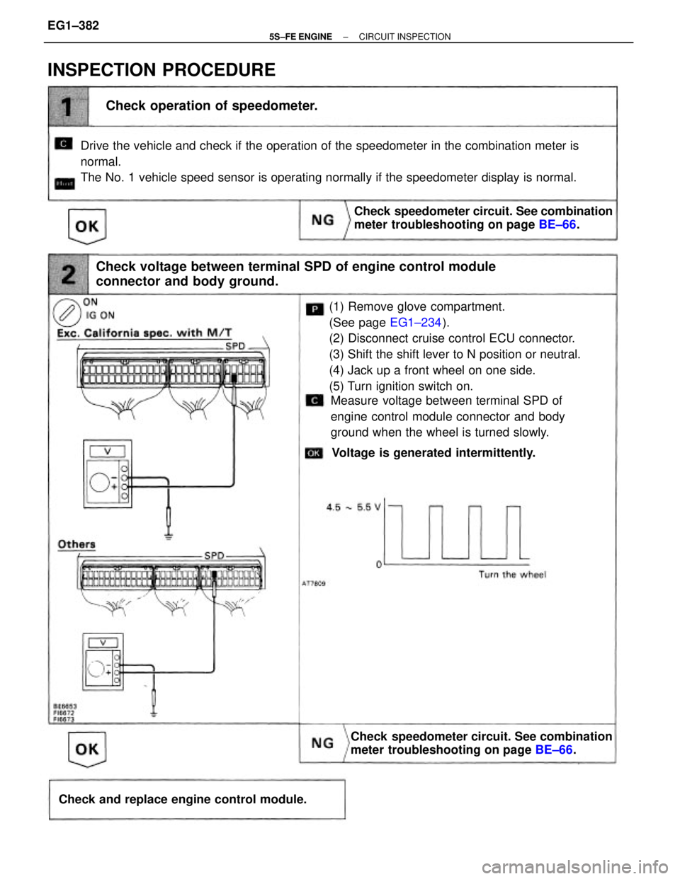
(1) Remove glove compartment.
(See page EG1±234).
(2) Disconnect cruise control ECU connector.
(3) Shift the shift lever to N position or neutral.
(4) Jack up a front wheel on one side.
(5) Turn ignition switch on. Drive the vehicle and check if the operation of the speedometer in the combination meter is
normal.
The No. 1 vehicle speed sensor is operating normally if the speedometer display is normal.
Check voltage between terminal SPD of engine control module
connector and body ground.
Check speedometer circuit. See combination
meter troubleshooting on page BE±66.
Check speedometer circuit. See combination
meter troubleshooting on page BE±66.
Check operation of speedometer.
Check and replace engine control module.
INSPECTION PROCEDURE
Measure voltage between terminal SPD of
engine control module connector and body
ground when the wheel is turned slowly.
Voltage is generated intermittently.
± 5S±FE ENGINECIRCUIT INSPECTIONEG1±382
Page 450 of 4770
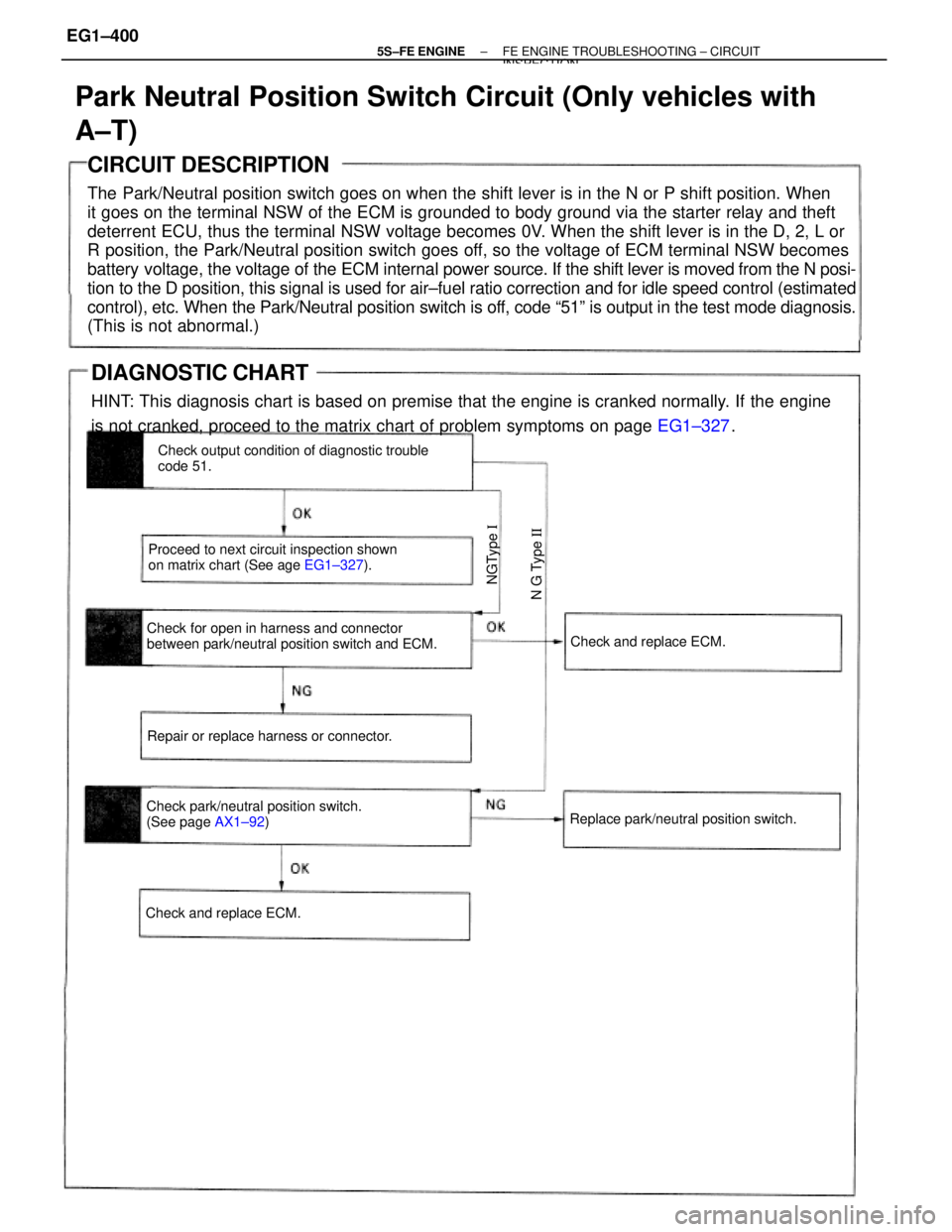
CIRCUIT DESCRIPTION
The Park/Neutral position switch goes on when the shift lever is in the N or P shift position. When
it goes on the terminal NSW of the ECM is grounded to body ground via the starter relay and theft
deterrent ECU, thus the terminal NSW voltage becomes 0V. When the shift lever is in the D, 2, L or
R position, the Park/Neutral position switch goes off, so the voltage of ECM terminal NSW becomes
battery voltage, the voltage of the ECM internal power source. If the shift lever is moved from the N posi-
tion to the D position, this signal is used for air±fuel ratio correction and for idle speed control (estimated
control), etc. When the Park/Neutral position switch is off, code ª51º is output in the test mode diagnosis.
(This is not abnormal.)
Park Neutral Position Switch Circuit (Only vehicles with
A±T)
Check for open in harness and connector
between park/neutral position switch and ECM.Check output condition of diagnostic trouble
code 51.
Proceed to next circuit inspection shown
on matrix chart (See age EG1±327).
Check park/neutral position switch.
(See page AX1±92) Repair or replace harness or connector.
Replace park/neutral position switch.Check and replace ECM.
Check and replace ECM.
N G Type II NGType I
DIAGNOSTIC CHART
HINT: This diagnosis chart is based on premise that the engine is cranked normally. If the engine
is not cranked, proceed to the matrix chart of problem symptoms on page EG1±327.
± 5S±FE ENGINEFE ENGINE TROUBLESHOOTING ± CIRCUITINSPECTION
EG1±400
Page 1107 of 4770
If you’ ll be doing some of your own maintenance and repair work
on your vehicle, a Toyota service manual will be one of your most
valuable tools. Toyota offers three types of manuals to assist
do- it- yourselfers. To order any of the following manuals, call
Toyota’s service publications department at (800) 622- 2033.
Vehicle Repair Manual
This is the same manual used by professional technicians in Toyota
dealerships throughout the United States. It is fully illustrated and
includes maintenance and repair procedures for all vehicle mechan-
ical systems. It also includes instructions for vehicle tune- ups.
Electrical Systems Manual
This manual provides detailed wiring diagrams for each electri-
cal system in your vehicle, along with troubleshooting tips and
repair procedures.
Automatic Transmission/Transaxle Repair Manual
This manual includes complete procedures for overhauling the
automatic transmission/transaxle of your vehicle.For information on basic do- it- yourself maintenance items,
see the “General Maintenance and Care” and “Do- It-
Yourself Maintenance” sections of your
Owner’s Manual.
Toyota Service Manuals
TOYOTA MAINTENANCE & REPAIR SUPPORT15
Page 1151 of 4770

A INTRODUCTION
This manual consists of the following 12 sections:
No.
SectionDescription
A
INDEXIndex of the contents of this manual.
A
INTRODUCTIONBrief explanation of each section.
BHOW TO USE THIS
MANUALInstructions on how to use this manual.
CTROUBLE±
SHOOTINGDescribes the basic inspection procedures for electrical circuits.
DABBREVIATIONSDefines the abbreviations used in this manual.
E
GLOSSARY OF
TERMS AND
SYMBOLS
Defines the symbols and functions of major parts.
FRELAY LOCATIONSShows position of the Electronic Control Unit, Relays, Relay Block, etc.
This section is closely related to the system circuit.
GELECTRICAL
WIRING ROUTINGDescribes position of Parts Connectors, Splice points, Ground points, etc.
This section is closely related to the system circuit.
INDEXIndex of the system circuits.
H
SYSTEM CIRCUITS
Electrical circuits of each system are shown from the power supply through ground
points. Wiring connections and their positions are shown and classified by code
according to the connection method. (Refer to the section, ºHow to use this manualº).
The ºSystem Outlineº and ºService Hintsº useful for troubleshooting are also contained
in this section.
IGROUND POINTSShows ground positions of all parts described in this manual.
J
OVERALL
ELECTRICAL
WIRING DIAGRAM
Provides circuit diagrams showing the circuit connections.
KPOWER SOURCE
(Current Flow Chart)Describes power distribution from the power supply to various electrical loads.
LPART NUMBER OF
CONNECTORSIndicates the part number of the connectors used in this manual.
Page 1152 of 4770

HOW TO USE THIS MANUAL B
This manual provides information on the electrical circuits installed on vehicles by
dividing them into a circuit for each system.
The actual wiring of each system circuit is shown from the point where the power
source is received from the battery as far as each ground point. (All circuit
diagrams are shown with the switches in the OFF position.)
When troubleshooting any problem, first understand the operation of the circuit
where the problem was detected (see System Circuit section), the power source
supplying power to that circuit (see Power Source section), and the ground points
(see Ground Points section). See the System Outline to understand the circuit
operation.
When the circuit operation is understood, begin troubleshooting of the problem
circuit to isolate the cause. Use Relay Location and Electrical Wiring Routing
sections to find each part, junction block and wiring harness connectors, wiring
harness and wiring harness connectors, splice points, and ground points of each
system circuit. Internal wiring for each junction block is also provided for better
understanding of connection within a junction block.
Wiring related to each system is indicated in each system circuit by arrows
(from__, to__). When overall connections are required, see the Overall Electrical
Wiring Diagram at the end of this manual.
Page 1156 of 4770
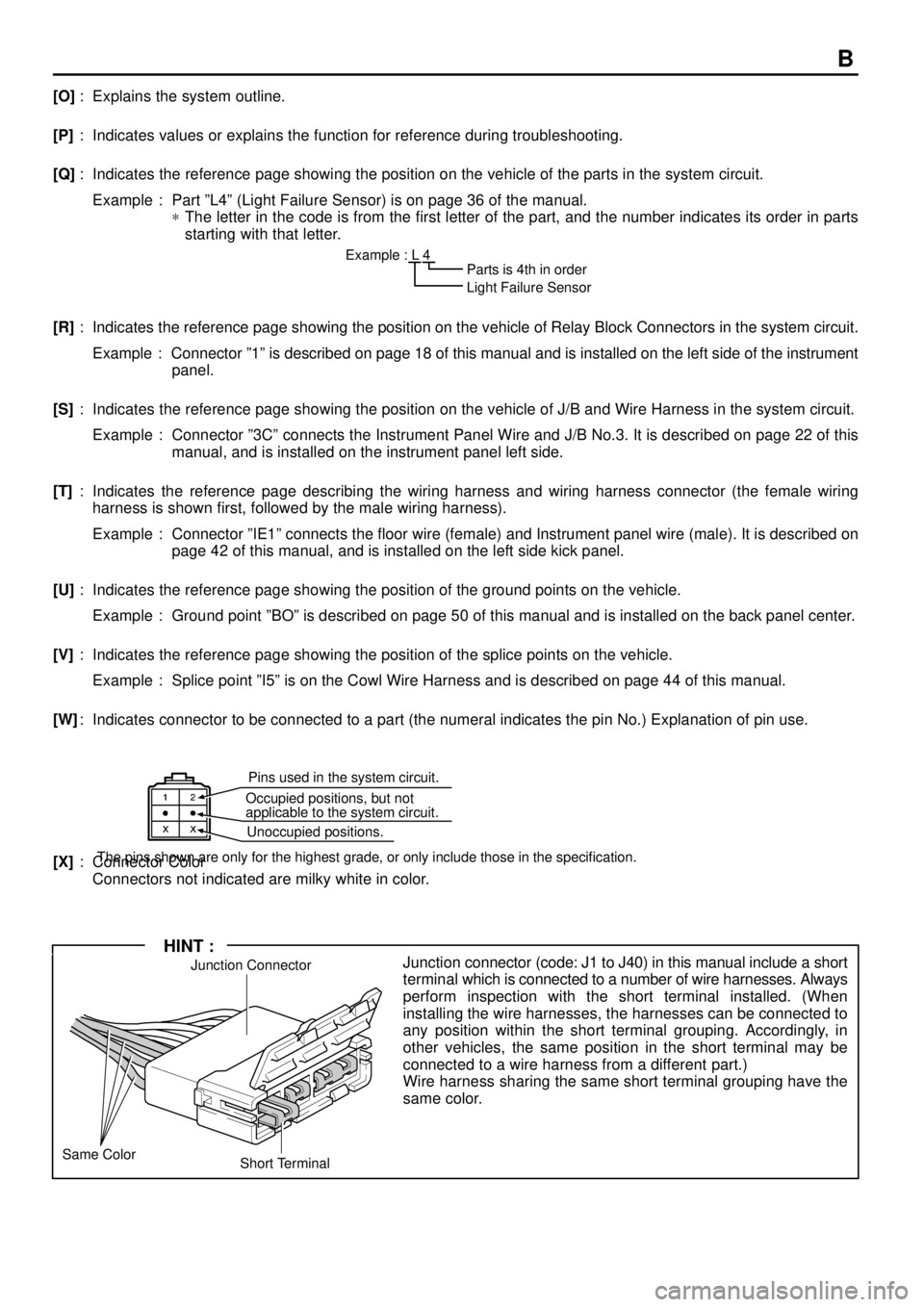
Pins used in the system circuit.
Occupied positions, but not
applicable to the system circuit.
Unoccupied positions.
The pins shown are only for the highest grade, or only include those in the specification.
Junction Connector
Short Terminal Same ColorJunction connector (code: J1 to J40) in this manual include a short
terminal which is connected to a number of wire harnesses. Always
perform inspection with the short terminal installed. (When
installing the wire harnesses, the harnesses can be connected to
any position within the short terminal grouping. Accordingly, in
other vehicles, the same position in the short terminal may be
connected to a wire harness from a different part.)
Wire harness sharing the same short terminal grouping have the
same color.
HINT :
B
[O]: Explains the system outline.
[P]: Indicates values or explains the function for reference during troubleshooting.
[Q]: Indicates the reference page showing the position on the vehicle of the parts in the system circuit.
Example : Part ºL4º (Light Failure Sensor) is on page 36 of the manual.
*The letter in the code is from the first letter of the part, and the number indicates its order in parts
starting with that letter.
Example : L 4
� �Parts is 4th in order
Light Failure Sensor
[R]: Indicates the reference page showing the position on the vehicle of Relay Block Connectors in the system circuit.
Example : Connector º1º is described on page 18 of this manual and is installed on the left side of the instrument
panel.
[S]: Indicates the reference page showing the position on the vehicle of J/B and Wire Harness in the system circuit.
Example : Connector º3Cº connects the Instrument Panel Wire and J/B No.3. It is described on page 22 of this
manual, and is installed on the instrument panel left side.
[T]: Indicates the reference page describing the wiring harness and wiring harness connector (the female wiring
harness is shown first, followed by the male wiring harness).
Example : Connector ºIE1º connects the floor wire (female) and Instrument panel wire (male). It is described on
page 42 of this manual, and is installed on the left side kick panel.
[U]: Indicates the reference page showing the position of the ground points on the vehicle.
Example : Ground point ºBOº is described on page 50 of this manual and is installed on the back panel center.
[V]: Indicates the reference page showing the position of the splice points on the vehicle.
Example : Splice point ºI5º is on the Cowl Wire Harness and is described on page 44 of this manual.
[W]: Indicates connector to be connected to a part (the numeral indicates the pin No.) Explanation of pin use.
[X]: Connector Color
Connectors not indicated are milky white in color.
Page 1157 of 4770
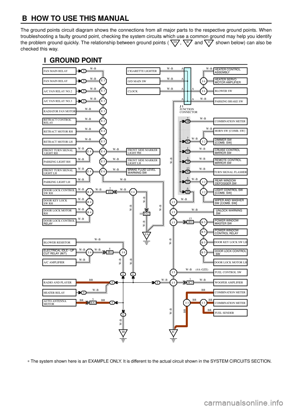
B HOW TO USE THIS MANUAL
The ground points circuit diagram shows the connections from all major parts to the respective ground points. When
troubleshooting a faulty ground point, checking the system circuits which use a common ground may help you identify
the problem ground quickly. The relationship between ground points (
EA, IB and IC shown below) can also be
checked this way.
���� ���� ���� ���� ���� ���� ���� ���� ���� ���� ���� ���� ���� ���� ���� ���� ���� ���� ����
I GROUND POINT
FAN MAIN RELAY
FAN MAIN RELAY
A/C FAN RELAY NO.2
A/C FAN RELAY NO.3
RADIATOR FAN MOTOR
RETRACT CONTROL
RELAY
RETRACT MOTOR RH
RETRACT MOTOR LH
FRONT TURN SIGNAL
LIGHT RH
PARKING LIGHT RH
FRONT TURN SIGNAL
LIGHT LH
PARKING LIGHT LH
DOOR LOCK CONTROL
SW RH
DOOR KEY LOCK
SW RH
DOOR LOCK MOTOR
RH
BLOWER RESISTOR
A/C AMPLIFIER
RADIO AND PLAYER
HEATER RELAY
AUTO ANTENNA
MOTOR
BLOWER SW
PARKING BRAKE SW
COMBINATION METER
HORN SW [COMB. SW]
TURN SIGNAL FLASHER
DOOR KEY LOCK SW LH
DOOR LOCK MOTOR LH
FUEL CONTROL SW
WOOFER AMPLIFIER
COMBINATION METER
COMBINATION METER
FUEL SENDER
CIGARETTE LIGHTER
O/D MAIN SW
CLOCK
5
5
5
5
4
4
4
4
4BA15
IB18
EA2 10
3E5
3E
6 3G
13 3F
3 3D
1 3B
7
ID115
IC33
IA12
E 3
A
A AW±B
W±BW±B W±B
W±B W±B
W±B
W±B
W±B
W±B
W±B
W±B
W±B
W±B
W±B W±BW±B W±B W±B W±B
W±B W±B
W±BW±B
W±B
W±B
W±B W±B
W±B
BR
W±B
BR BRW±BW±B
W±B
W±B
W±B
W±B
W±B
W±B
W±B
W±B
W±B W±B
W±B
W±B
W±B
W±B
BR W±B
BR BR
BR W±B W±BW±B
W±BW±BBR W±B (4A±GZE)
W±B A A A
I 6
I 6
I 2
I 2
I 2
B 5I 5
I 5
I 5
B 5
B 5
B 5
I 5
I 5
I 3I 3
E 3
E 3
E 3
E 2
E 4
E 5
E 4
E 5
E 6E 4
E 4
B 4
EAI 4
B 4
B 4
I 4I 8
IBIC
3C7
4
JUNCTION
CONNECTOR J 1
4
DOOR LOCK CONTROL
RELAY
ELECTRICAL IDLE-UP
CUT RELAY (M/T)FRONT SIDE MARKER
LIGHT RH
FRONT SIDE MARKER
LIGHT LH
BRAKE FLUID LEVEL
WARNING SW
UNLOCK WARNING
SW WIPER AND WASHER
SW [COMB. SW] LIGHT CONTROL SW
[COMB. SW] HEATER CONTROL
ASSEMBLY
HEATER SERVO
MOTOR AMPLIFIER
DIMMER SW
[COMB. SW]
CRUISE CONTROL
MIRROR SW
REAR WINDOW
DEFOGGER SW
POWER WINDOW
MASTER SW
POWER WINDOW
CONTROL RELAY
DOOR LOCK CONTROL
SW
REMOTE CONTROL
MIRROR SW
* The system shown here is an EXAMPLE ONLY. It is different to the actual circuit shown in the SYSTEM CIRCUITS SECTION.
Page 1159 of 4770
![TOYOTA CAMRY 2000 Service User Guide To Ignition SW
IG Terminal
Fuse
Voltmeter SW 1
Relay
SW 2Solenoid[A]
[B]
[C]
Ohmmeter
SW
Ohmmeter
Diode
Digital Type Analog Type
C TROUBLESHOOTING
VOLTAGE CHECK
(a)Establish conditions in which volta TOYOTA CAMRY 2000 Service User Guide To Ignition SW
IG Terminal
Fuse
Voltmeter SW 1
Relay
SW 2Solenoid[A]
[B]
[C]
Ohmmeter
SW
Ohmmeter
Diode
Digital Type Analog Type
C TROUBLESHOOTING
VOLTAGE CHECK
(a)Establish conditions in which volta](/img/14/57447/w960_57447-1158.png)
To Ignition SW
IG Terminal
Fuse
Voltmeter SW 1
Relay
SW 2Solenoid[A]
[B]
[C]
Ohmmeter
SW
Ohmmeter
Diode
Digital Type Analog Type
C TROUBLESHOOTING
VOLTAGE CHECK
(a)Establish conditions in which voltage is present at the check
point.
Example:
[A] ± Ignition SW on
[B] ± Ignition SW and SW 1 on
[C] ± Ignition SW, SW 1 and Relay on (SW 2 off)
(b)Using a voltmeter, connect the negative lead to a good ground
point or negative battery terminal, and the positive lead to the
connector or component terminal.
This check can be done with a test light instead of a voltmeter.
CONTINUITY AND RESISTANCE CHECK
(a)Disconnect the battery terminal or wire so there is no voltage
between the check points.
(b)Contact the two leads of an ohmmeter to each of the check
points.
If the circuit has diodes, reverse the two leads and check
again.
When contacting the negative lead to the diode positive side
and the positive lead to the negative side, there should be
continuity.
When contacting the two leads in reverse, there should be no
continuity.
(c)Use a volt/ohmmeter with high impedance (10 kW/V
minimum) for troubleshooting of the electrical circuit.
Page 1161 of 4770
![TOYOTA CAMRY 2000 Service User Guide 10
3
0.2
11
(mm) Reference:
Tool Up Example:
(Case 1)
Terminal Retainer
Terminal Retainer
[Retainer at Full Lock Position]
[Retainer at Temporary Lock Position]StopperTerminal
Retainer
Secondary
Locki TOYOTA CAMRY 2000 Service User Guide 10
3
0.2
11
(mm) Reference:
Tool Up Example:
(Case 1)
Terminal Retainer
Terminal Retainer
[Retainer at Full Lock Position]
[Retainer at Temporary Lock Position]StopperTerminal
Retainer
Secondary
Locki](/img/14/57447/w960_57447-1160.png)
10
3
0.2
11
(mm) Reference:
Tool Up Example:
(Case 1)
Terminal Retainer
Terminal Retainer
[Retainer at Full Lock Position]
[Retainer at Temporary Lock Position]StopperTerminal
Retainer
Secondary
Locking Device Example:
(Case 2)
C TROUBLESHOOTING
HOW TO REPLACE TERMINAL
(with terminal retainer or secondary locking device)
1.PREPARE THE SPECIAL TOOL
HINT : To remove the terminal from the connector, please
construct and use the special tool or like object shown on
the left.
2.DISCONNECT CONNECTOR
3.DISENGAGE THE SECONDARY LOCKING DEVICE OR
TERMINAL RETAINER.
(a)Locking device must be disengaged before the terminal
locking clip can be released and the terminal removed from
the connector.
(b)Use a special tool or the terminal pick to unlock the secondary
locking device or terminal retainer.
NOTICE:
Do not remove the terminal retainer from connector body.
[A] For Non±Waterproof Type Connector
HINT : The needle insertion position varies according to the
connector's shape (number of terminals etc.), so
check the position before inserting it.
ºCase 1º
Raise the terminal retainer up to the temporary lock
position.
ºCase 2º
Open the secondary locking device.
Page 1163 of 4770
![TOYOTA CAMRY 2000 Service User Guide Retainer at
Full Lock Position
[Male] [Female]
Retainer at
Temporary Lock Position
Locking Lug
Tool
C TROUBLESHOOTING
Push the terminal retainer down to the temporary lock position.
(c)Release the lo TOYOTA CAMRY 2000 Service User Guide Retainer at
Full Lock Position
[Male] [Female]
Retainer at
Temporary Lock Position
Locking Lug
Tool
C TROUBLESHOOTING
Push the terminal retainer down to the temporary lock position.
(c)Release the lo](/img/14/57447/w960_57447-1162.png)
Retainer at
Full Lock Position
[Male] [Female]
Retainer at
Temporary Lock Position
Locking Lug
Tool
C TROUBLESHOOTING
Push the terminal retainer down to the temporary lock position.
(c)Release the locking lug from terminal and pull the terminal out
from rear.
4.INSTALL TERMINAL TO CONNECTOR
(a)Insert the terminal.
HINT:
1. Make sure the terminal is positioned correctly.
2. Insert the terminal until the locking lug locks firmly.
3. Insert the terminal with terminal retainer in the temporary lock
position.
(b)Push the secondary locking device or terminal retainer in to
the full lock position.
5.CONNECT CONNECTOR