TOYOTA CAMRY 2000 Service Repair Manual
Manufacturer: TOYOTA, Model Year: 2000, Model line: CAMRY, Model: TOYOTA CAMRY 2000Pages: 4770, PDF Size: 86.41 MB
Page 141 of 4770
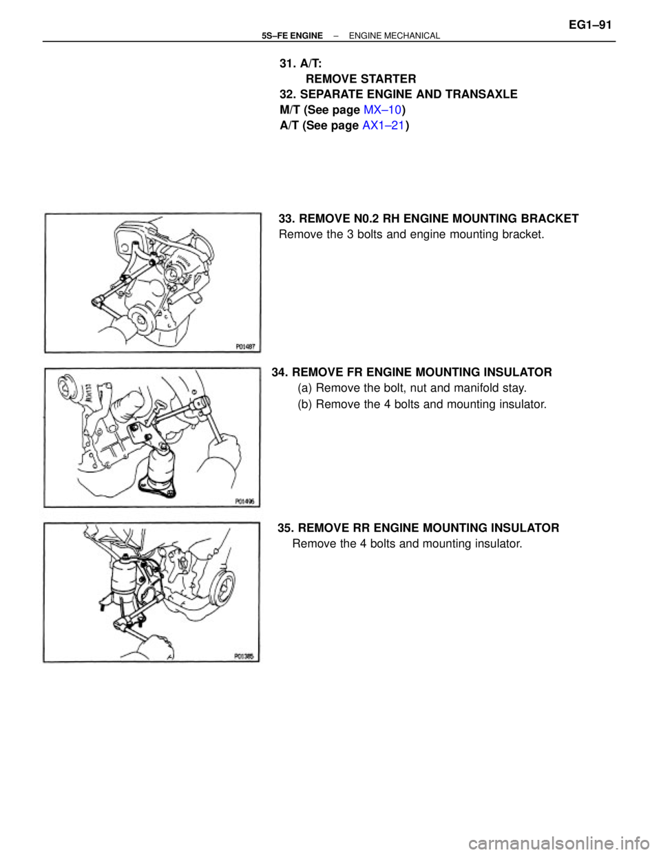
31. A/T:
REMOVE STARTER
32. SEPARATE ENGINE AND TRANSAXLE
M/T (See page MX±10)
A/T (See page AX1±21)
34. REMOVE FR ENGINE MOUNTING INSULATOR
(a) Remove the bolt, nut and manifold stay.
(b) Remove the 4 bolts and mounting insulator. 33. REMOVE N0.2 RH ENGINE MOUNTING BRACKET
Remove the 3 bolts and engine mounting bracket.
35. REMOVE RR ENGINE MOUNTING INSULATOR
Remove the 4 bolts and mounting insulator.
± 5S±FE ENGINEENGINE MECHANICALEG1±91
Page 142 of 4770
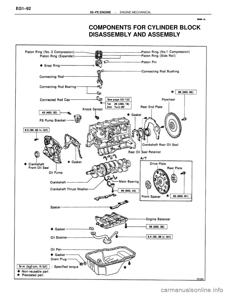
COMPONENTS FOR CYLINDER BLOCK
DISASSEMBLY AND ASSEMBLY
± 5S±FE ENGINEENGINE MECHANICALEG1±92
Page 143 of 4770
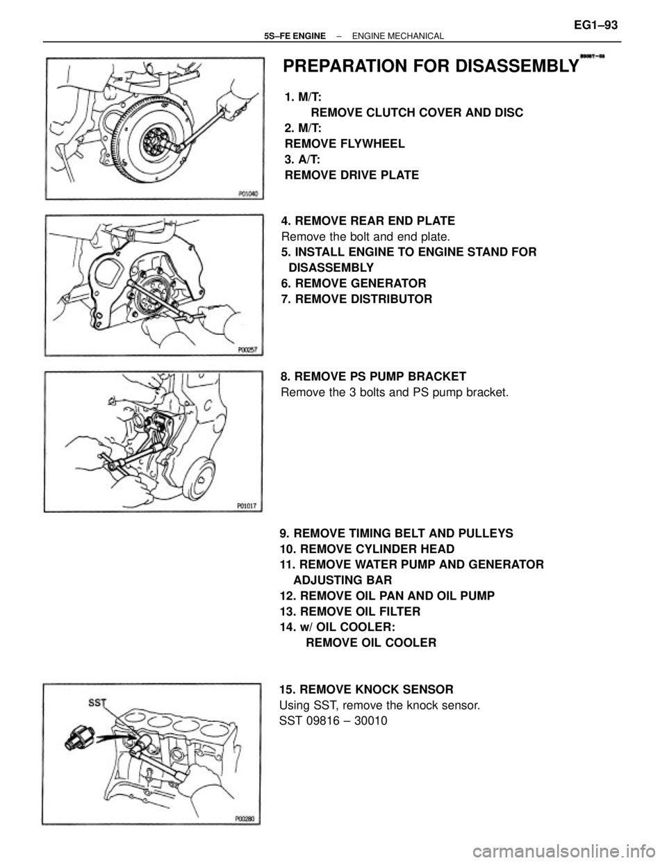
9. REMOVE TIMING BELT AND PULLEYS
10. REMOVE CYLINDER HEAD
11. REMOVE WATER PUMP AND GENERATOR
ADJUSTING BAR
12. REMOVE OIL PAN AND OIL PUMP
13. REMOVE OIL FILTER
14. w/ OIL COOLER:
REMOVE OIL COOLER 4. REMOVE REAR END PLATE
Remove the bolt and end plate.
5. INSTALL ENGINE TO ENGINE STAND FOR
DISASSEMBLY
6. REMOVE GENERATOR
7. REMOVE DISTRIBUTOR1. M/T:
REMOVE CLUTCH COVER AND DISC
2. M/T:
REMOVE FLYWHEEL
3. A/T:
REMOVE DRIVE PLATE
15. REMOVE KNOCK SENSOR
Using SST, remove the knock sensor.
SST 09816 ± 300108. REMOVE PS PUMP BRACKET
Remove the 3 bolts and PS pump bracket.
PREPARATION FOR DISASSEMBLY
± 5S±FE ENGINEENGINE MECHANICALEG1±93
Page 144 of 4770
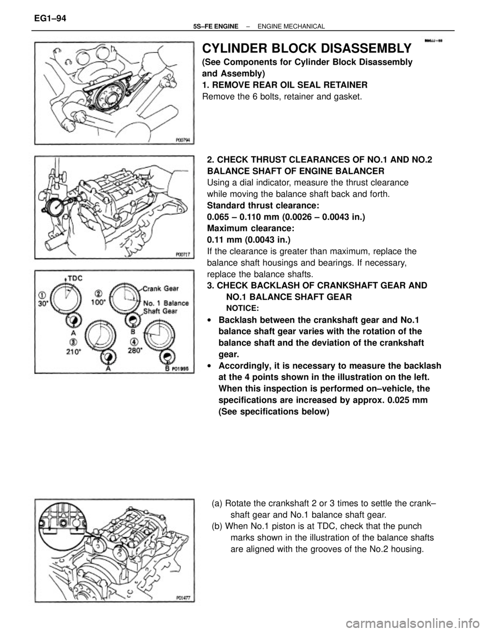
2. CHECK THRUST CLEARANCES OF NO.1 AND NO.2
BALANCE SHAFT OF ENGINE BALANCER
Using a dial indicator, measure the thrust clearance
while moving the balance shaft back and forth.
Standard thrust clearance:
0.065 ± 0.110 mm (0.0026 ± 0.0043 in.)
Maximum clearance:
0.11 mm (0.0043 in.)
If the clearance is greater than maximum, replace the
balance shaft housings and bearings. If necessary,
replace the balance shafts.
3. CHECK BACKLASH OF CRANKSHAFT GEAR AND
NO.1 BALANCE SHAFT GEAR
NOTICE:
wBacklash between the crankshaft gear and No.1
balance shaft gear varies with the rotation of the
balance shaft and the deviation of the crankshaft
gear.
wAccordingly, it is necessary to measure the backlash
at the 4 points shown in the illustration on the left.
When this inspection is performed on±vehicle, the
specifications are increased by approx. 0.025 mm
(See specifications below)
CYLINDER BLOCK DISASSEMBLY
(See Components for Cylinder Block Disassembly
and Assembly)
1. REMOVE REAR OIL SEAL RETAINER
Remove the 6 bolts, retainer and gasket.
(a) Rotate the crankshaft 2 or 3 times to settle the crank±
shaft gear and No.1 balance shaft gear.
(b) When No.1 piston is at TDC, check that the punch
marks shown in the illustration of the balance shafts
are aligned with the grooves of the No.2 housing.
± 5S±FE ENGINEENGINE MECHANICALEG1±94
Page 145 of 4770
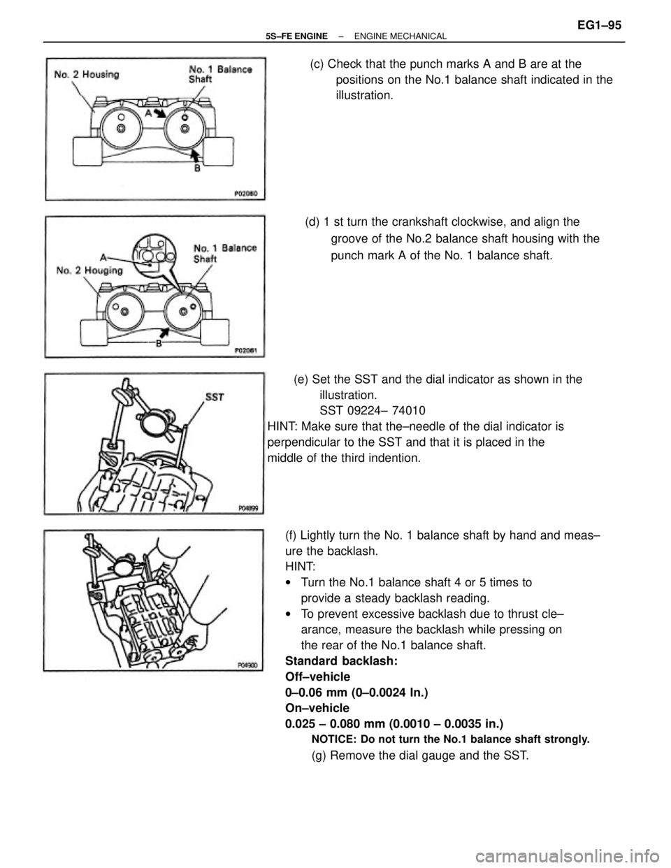
(f) Lightly turn the No. 1 balance shaft by hand and meas±
ure the backlash.
HINT:
wTurn the No.1 balance shaft 4 or 5 times to
provide a steady backlash reading.
wTo prevent excessive backlash due to thrust cle±
arance, measure the backlash while pressing on
the rear of the No.1 balance shaft.
Standard backlash:
Off±vehicle
0±0.06 mm (0±0.0024 In.)
On±vehicle
0.025 ± 0.080 mm (0.0010 ± 0.0035 in.)
NOTICE: Do not turn the No.1 balance shaft strongly.
(g) Remove the dial gauge and the SST. (e) Set the SST and the dial indicator as shown in the
illustration.
SST 09224± 74010
HINT: Make sure that the±needle of the dial indicator is
perpendicular to the SST and that it is placed in the
middle of the third indention.(d) 1 st turn the crankshaft clockwise, and align the
groove of the No.2 balance shaft housing with the
punch mark A of the No. 1 balance shaft. (c) Check that the punch marks A and B are at the
positions on the No.1 balance shaft indicated in the
illustration.
± 5S±FE ENGINEENGINE MECHANICALEG1±95
Page 146 of 4770
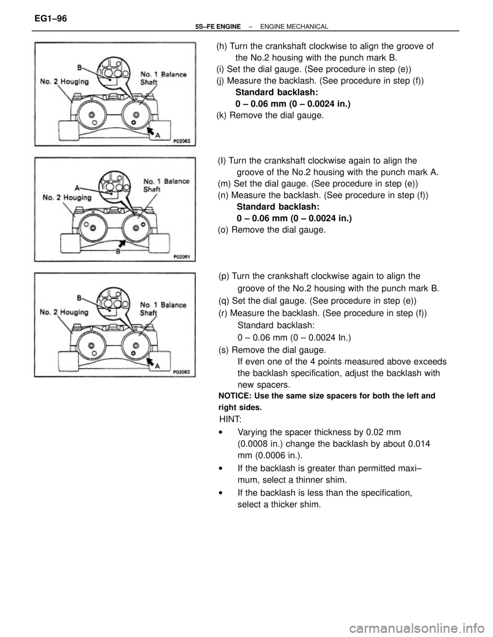
(p) Turn the crankshaft clockwise again to align the
groove of the No.2 housing with the punch mark B.
(q) Set the dial gauge. (See procedure in step (e))
(r) Measure the backlash. (See procedure in step (f))
Standard backlash:
0 ± 0.06 mm (0 ± 0.0024 In.)
(s) Remove the dial gauge.
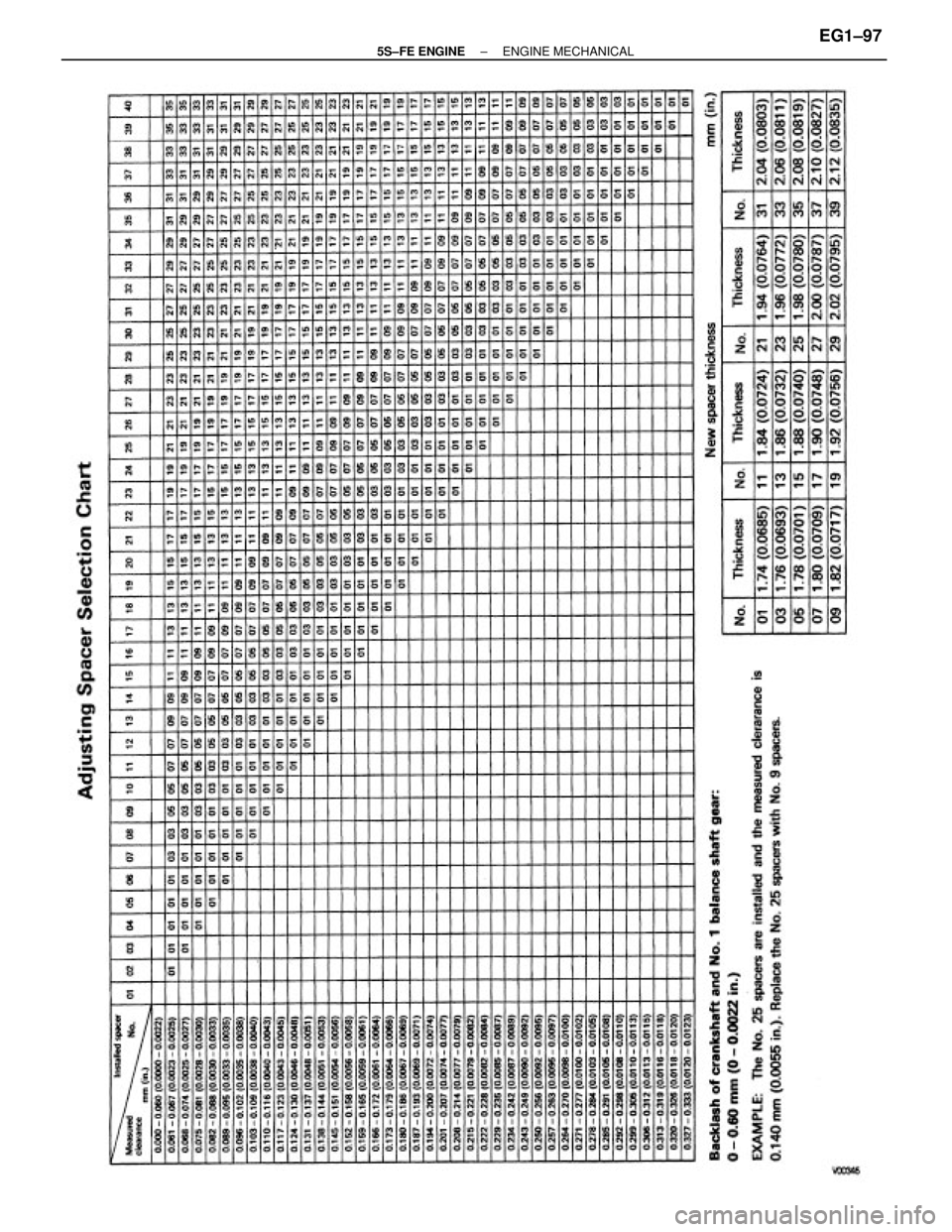
If even one of the 4 points measured above exceeds
the backlash specification, adjust the backlash with
new spacers.
NOTICE: Use the same size spacers for both the left and
right sides.
HINT:
wVarying the spacer thickness by 0.02 mm
(0.0008 in.) change the backlash by about 0.014
mm (0.0006 in.).
wIf the backlash is greater than permitted maxi±
mum, select a thinner shim.
wIf the backlash is less than the specification,
select a thicker shim. (I) Turn the crankshaft clockwise again to align the
groove of the No.2 housing with the punch mark A.
(m) Set the dial gauge. (See procedure in step (e))
(n) Measure the backlash. (See procedure in step (f))
Standard backlash:
0 ± 0.06 mm (0 ± 0.0024 in.)
(o) Remove the dial gauge. (h) Turn the crankshaft clockwise to align the groove of
the No.2 housing with the punch mark B.
(i) Set the dial gauge. (See procedure in step (e))
(j) Measure the backlash. (See procedure in step (f))
Standard backlash:
0 ± 0.06 mm (0 ± 0.0024 in.)
(k) Remove the dial gauge.
± 5S±FE ENGINEENGINE MECHANICALEG1±96
Page 147 of 4770
± 5S±FE ENGINEENGINE MECHANICALEG1±97
Page 148 of 4770
5. CHECK CONNECTING ROD THRUST CLEARANCE
Using a dial indicator, measure the thrust clearance
while moving the connecting rod back and forth.
Standard thrust clearance:
0.160 ± 0.312 mm (0.0063 ± 0.0123 in.)
Maximum thrust clearance:
0.36 mm (0.0138 in.)
If the thrust clearance is greater than maximum, re±
place the connecting rod assembly. If necessary, re±
place the crankshaft.
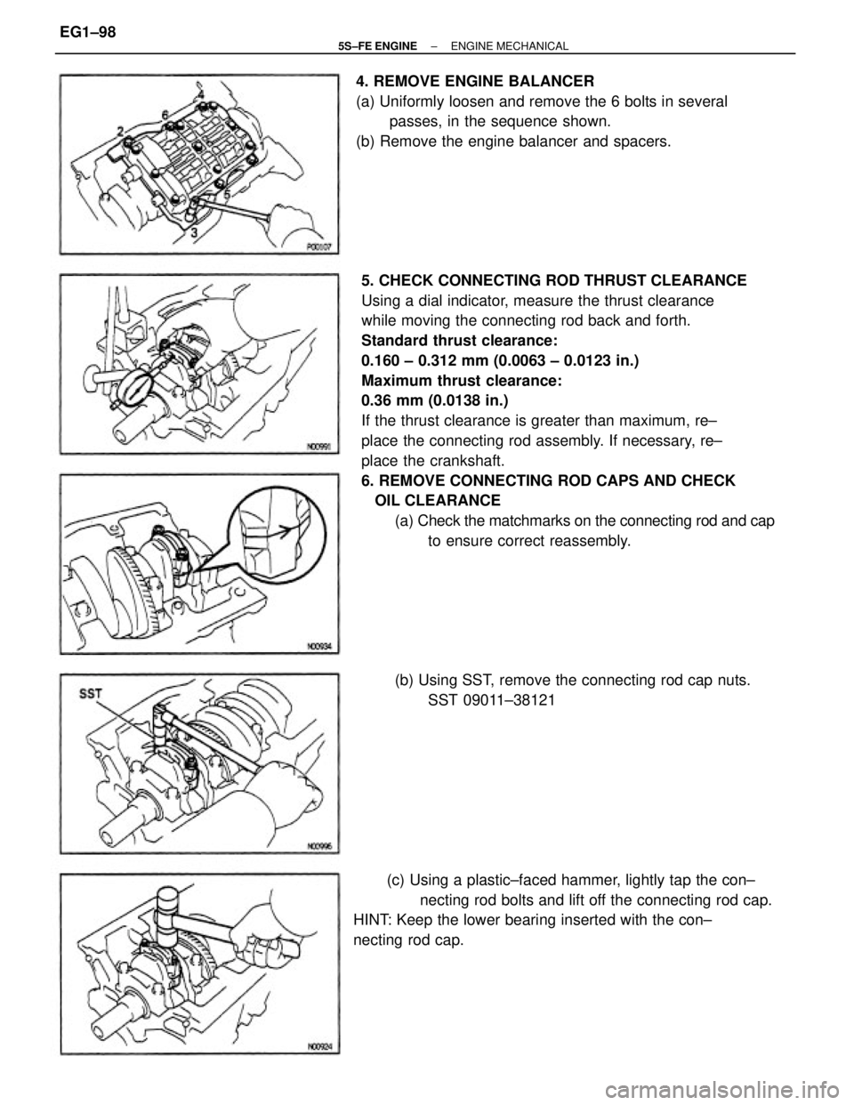
6. REMOVE CONNECTING ROD CAPS AND CHECK
OIL CLEARANCE
(a) Check the matchmarks on the connecting rod and cap
to ensure correct reassembly.
(c) Using a plastic±faced hammer, lightly tap the con±
necting rod bolts and lift off the connecting rod cap.
HINT: Keep the lower bearing inserted with the con±
necting rod cap.4. REMOVE ENGINE BALANCER
(a) Uniformly loosen and remove the 6 bolts in several
passes, in the sequence shown.
(b) Remove the engine balancer and spacers.
(b) Using SST, remove the connecting rod cap nuts.
SST 09011±38121
± 5S±FE ENGINEENGINE MECHANICALEG1±98
Page 149 of 4770
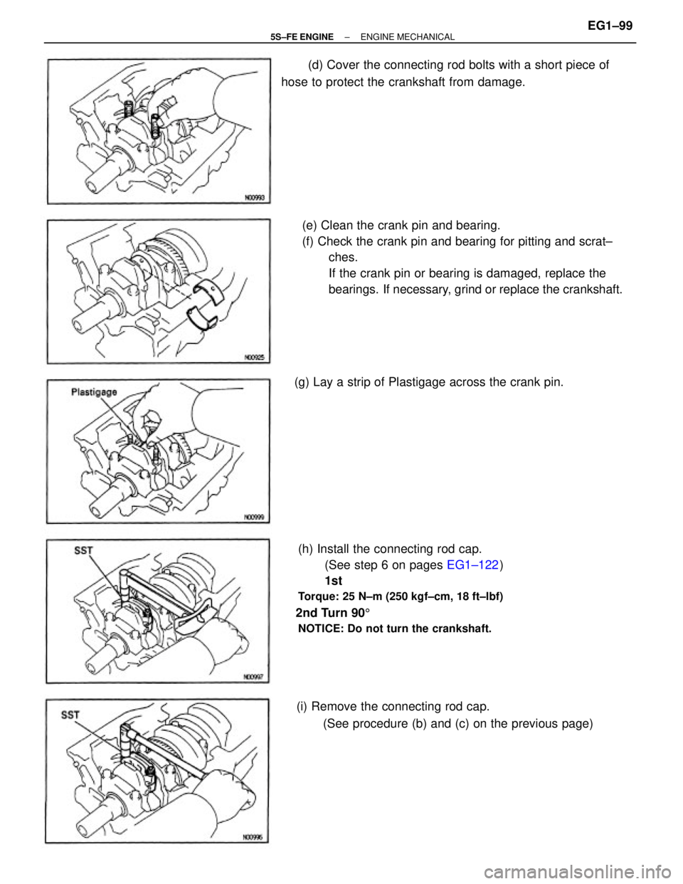
(e) Clean the crank pin and bearing.
(f) Check the crank pin and bearing for pitting and scrat±
ches.
If the crank pin or bearing is damaged, replace the
bearings. If necessary, grind or replace the crankshaft.
(h) Install the connecting rod cap.
(See step 6 on pages EG1±122)
1st
Torque: 25 N±m (250 kgf±cm, 18 ft±lbf)
2nd Turn 905
NOTICE: Do not turn the crankshaft.
(d) Cover the connecting rod bolts with a short piece of
hose to protect the crankshaft from damage.
(i) Remove the connecting rod cap.
(See procedure (b) and (c) on the previous page) (g) Lay a strip of Plastigage across the crank pin.
± 5S±FE ENGINEENGINE MECHANICALEG1±99
Page 150 of 4770
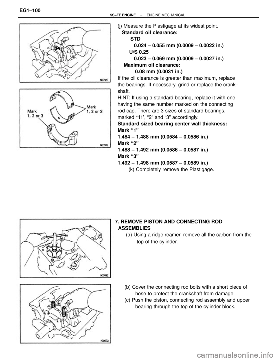
(j) Measure the Plastigage at its widest point.
Standard oil clearance:
STD
0.024 ± 0.055 mm (0.0009 ± 0.0022 in.)
U/S 0.25
0.023 ± 0.069 mm (0.0009 ± 0.0027 in.)
Maximum oil clearance:
0.08 mm (0.0031 in.)
If the oil clearance is greater than maximum, replace
the bearings. If necessary, grind or replace the crank±
shaft.
HINT: If using a standard bearing, replace it with one
having the same number marked on the connecting
rod cap. There are 3 sizes of standard bearings,
marked *11', ª2º and ª3º accordingly.
Standard sized bearing center wall thickness:
Mark ª1º
1.484 ± 1.488 mm (0.0584 ± 0.0586 in.)
Mark ª2º
1.488 ± 1.492 mm (0.0586 ± 0.0587 in.)
Mark ª3º
1.492 ± 1.498 mm (0.0587 ± 0.0589 in.)
(k) Completely remove the Plastigage.
(b) Cover the connecting rod bolts with a short piece of
hose to protect the crankshaft from damage.
(c) Push the piston, connecting rod assembly and upper
bearing through the top of the cylinder block. 7. REMOVE PISTON AND CONNECTING ROD
ASSEMBLIES
(a) Using a ridge reamer, remove all the carbon from the
top of the cylinder.
± 5S±FE ENGINEENGINE MECHANICALEG1±100