TOYOTA CAMRY 2012 XV50 / 9.G Navigation Manual
Manufacturer: TOYOTA, Model Year: 2012, Model line: CAMRY, Model: TOYOTA CAMRY 2012 XV50 / 9.GPages: 328, PDF Size: 5.67 MB
Page 281 of 328
281
2. ENTUNE OPERATION
8
APPS
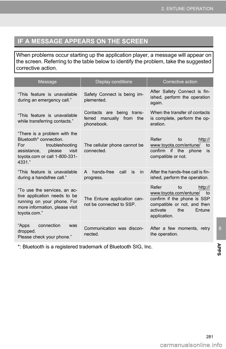
IF A MESSAGE APPEARS ON THE SCREEN
When problems occur starting up the application player, a message will appear on
the screen. Referring to the table below to identify the problem, take the suggested
corrective action.
MessageDisplay conditionsCorrective action
“This feature is unavailable
during an emergency call.”Safety Connect is being im-
plemented.After Safety Connect is fin-
ished, perform the operation
again.
“This feature is unavailable
while transferring contacts.”Contacts are being trans-
ferred manually from the
phonebook.When the transfer of contacts
is complete, perform the op-
eration.
“There is a problem with the
Bluetooth* connection.
For troubleshooting
assistance, please visit
toyota.com or call 1-800-331-
4331.”
The cellular phone cannot be
connected.
Refer to http://
www.toyota.com/entune/ to
confirm if the phone is
compatible or not.
“This feature is unavailable
during a handsfree call.”A hands-free call is in
progress.After the hands-free call is fin-
ished, perform the operation.
“To use the services, an ac-
tive application needs to be
running on your phone. For
more information, please visit
toyota.com.”
The Entune application can-
not be connected to SSP.
Refer to http://
www.toyota.com/entune/ to
confirm if the phone is SSP
compatible or not, and then
activate the Entune
application.
“Apps connection was
dropped.
Please check your phone.”Communication was discon-
nected.After a few moments, retry
the operation.
*: Bluetooth is a registered tr ademark of Bluetooth SIG, Inc.
Page 282 of 328
282
2. ENTUNE OPERATION
2. LINKING “APPS” AND NAVIGATION LOCAL FUNCTION
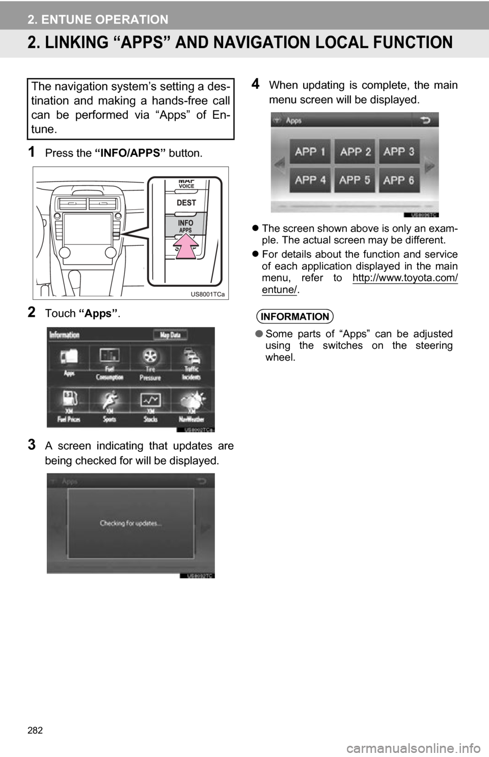
1Press the “INFO/APPS” button.
2Touch “Apps” .
3A screen indicating that updates are
being checked for will be displayed.
4When updating is complete, the main
menu screen will be displayed.
The screen shown above is only an exam-
ple. The actual screen may be different.
For details about the function and service
of each application displayed in the main
menu, refer to http://www.toyota.com/
entune/.
The navigation system’s setting a des-
tination and making a hands-free call
can be performed via “Apps” of En-
tune.
INFORMATION
●Some parts of “Apps” can be adjusted
using the switches on the steering
wheel.
Page 283 of 328
283
2. ENTUNE OPERATION
8
APPS
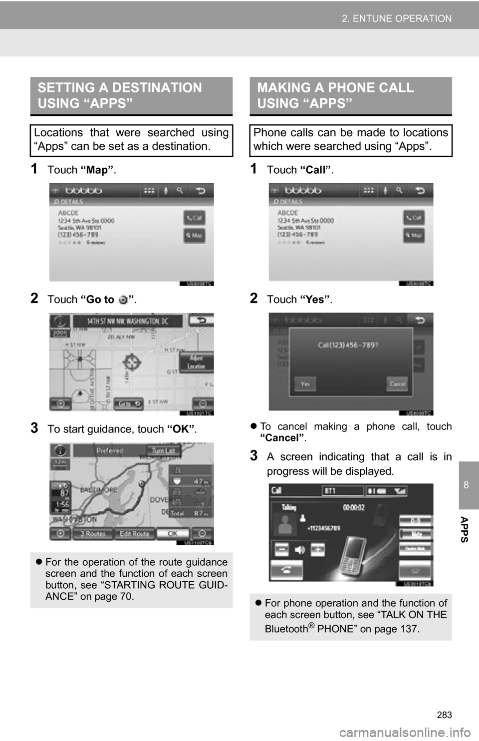
1Touch “Map”.
2Touch “Go to ” .
3To start guidance, touch “OK”.
1Touch “Call”.
2Touch “Yes”.
To cancel making a phone call, touch
“Cancel” .
3A screen indicating that a call is in
progress will be displayed.
SETTING A DESTINATION
USING “APPS”
Locations that were searched using
“Apps” can be set as a destination.
For the operation of the route guidance
screen and the function of each screen
button, see “STARTING ROUTE GUID-
ANCE” on page 70.
MAKING A PHONE CALL
USING “APPS”
Phone calls can be made to locations
which were searched using “Apps”.
For phone operation and the function of
each screen button, see “TALK ON THE
Bluetooth
® PHONE” on page 137.
Page 284 of 328
284
2. ENTUNE OPERATION
3. INPUTTING KEYWORD OPERATION
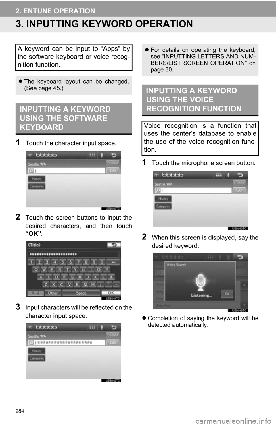
1Touch the character input space.
2Touch the screen buttons to input the
desired characters, and then touch
“OK”.
3Input characters will be reflected on the
character input space.
1Touch the microphone screen button.
2When this screen is displayed, say the
desired keyword.
Completion of saying the keyword will be
detected automatically.
A keyword can be input to “Apps” by
the software keyboard or voice recog-
nition function.
The keyboard layout can be changed.
(See page 45.)
INPUTTING A KEYWORD
USING THE SOFTWARE
KEYBOARD
For details on operating the keyboard,
see “INPUTTING LETTERS AND NUM-
BERS/LIST SCREEN OPERATION” on
page 30.
INPUTTING A KEYWORD
USING THE VOICE
RECOGNITION FUNCTION
Voice recognition is a function that
uses the center’s database to enable
the use of the voice recognition func-
tion.
Page 285 of 328
285
2. ENTUNE OPERATION
8
APPS
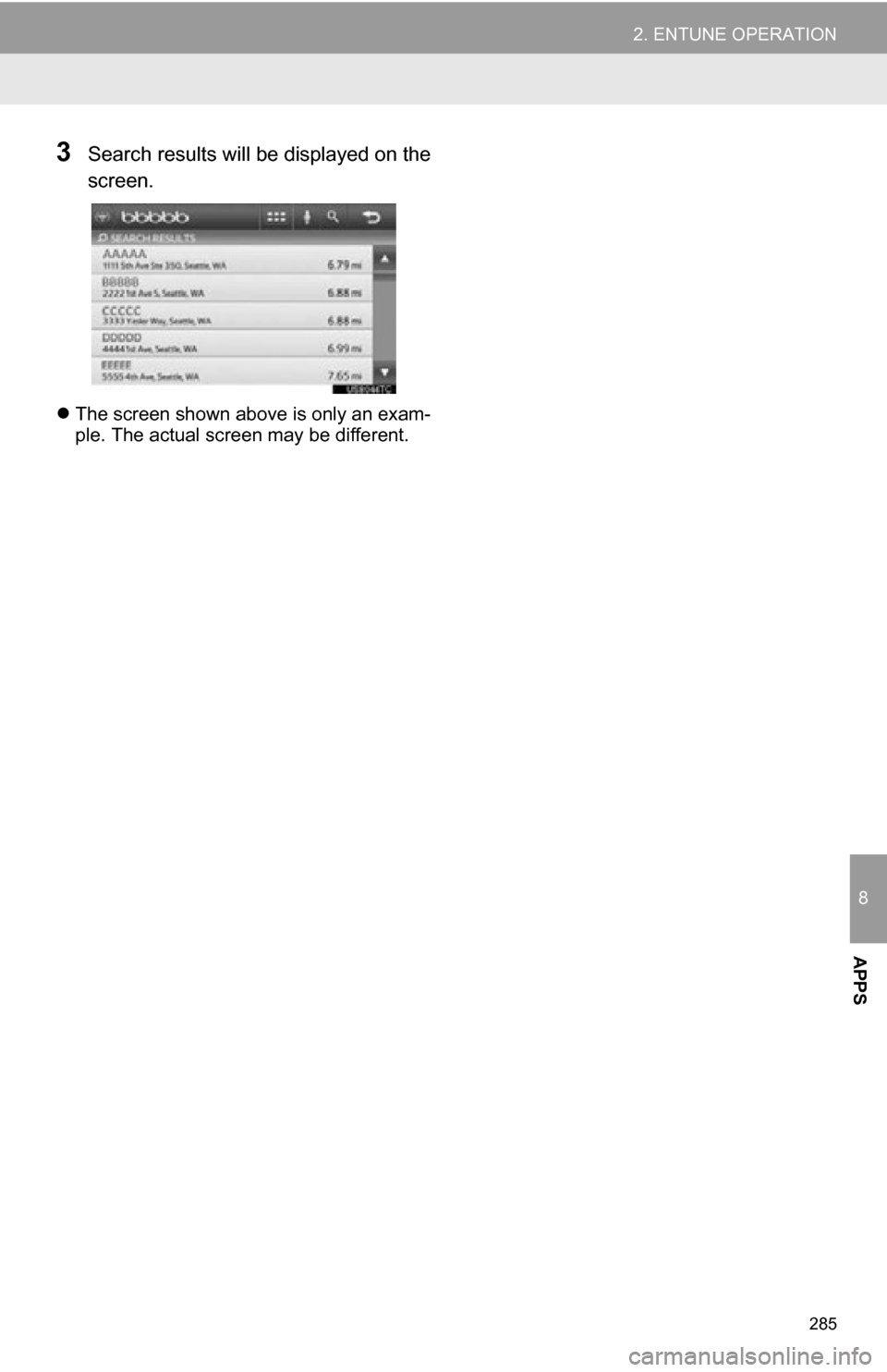
3Search results will be displayed on the
screen.
The screen shown above is only an exam-
ple. The actual screen may be different.
Page 286 of 328

286
2. ENTUNE OPERATION
Page 287 of 328
9
287
1
2
3
4
5
6
7
8
9
1. REAR VIEW MONITOR SYSTEM OPERATION ............................. 288
REAR VIEW MONITOR
GUIDE LINES .................................... 289
AREA DISPLAYED ON SCREEN........ 290
THE REAR VIEW MONITOR SYSTEM CAMERA ........................... 291
2. DRIVING PRECAUTIONS ........... 292
1REAR VIEW MONITOR
SYSTEM
PERIPHERAL MONITORING SYSTEM
Page 288 of 328
288
1. REAR VIEW MONITOR SYSTEM
1. REAR VIEW MONITOR SYSTEM OPERATION
1To display the rear view image on the
screen, place the shift lever in the “R”
position when the “POWER” <“EN-
GINE START STOP”> switch is in ON
a smart key system)
To display the rear view image on the
screen, place the shift lever in the “R”
position when the engine switch is in
the “ON” position. (Vehicles without a
smart key system)
The rear view monitor system assists
the driver by displaying an image of the
view behind the vehicle while backing
up. The image is displayed in reverse
on the screen. This reversed image is
a similar image to the one on the inside
rear view mirror.
If you move the shift lever out of the “R”
position, the screen returns to the previ-
ous screen. Operating another function
of the navigation system will display
another screen.
CAUTION
●Never depend on the rear view monitor
system entirely when backing up.
Always make sure your intended path is
clear.
Use caution, just as you would when
backing up any vehicle.
● Never back up while looking only at the
screen. The image on the screen is dif-
ferent from actual conditions. Depicted
distances between objects and flat sur-
faces will differ from actual distance. If
you back up while looking only at the
screen, you may hit a vehicle, a person
or an object. When backing up, be sure
to check behind and all around the vehi-
cle visually and with mirrors before pro-
ceeding.
● Always check the vehicle surrounding
area, because the guide lines are ancil-
lary lines.
● The guide lines are ancillary lines and
do not change even if the steering wheel
is turned.
● Do not use the system when the trunk is
not completely closed.
● Use your own eyes to confirm the vehi-
cle’s surroundings, as the displayed
image may become faint or dark, and
moving images will be distorted, or not
entirely visible when the outside temper-
ature is low. When backing up, be sure
to check behind and all around the vehi-
cle visually and with mirror before pro-
ceeding.
● Do not use the system in the following
cases:
• On icy or slick road surfaces, or in
snow.
• When using tire chains or emergency tires.
• On an uneven road, such as a slope.
Page 289 of 328
289
1. REAR VIEW MONITOR SYSTEM
9
PERIPHERAL MONITORING SYSTEM
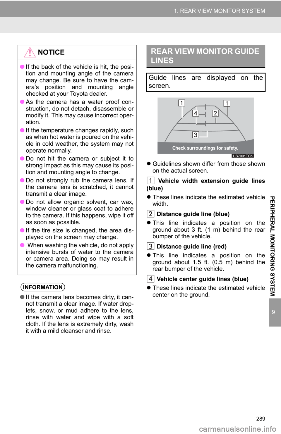
Guidelines shown differ from those shown
on the actual screen.
Vehicle width extension guide lines
(blue)
These lines indicate the estimated vehicle
width.
Distance guide line (blue)
This line indicates a position on the
ground about 3 ft. (1 m) behind the rear
bumper of the vehicle.
Distance guide line (red)
This line indicates a position on the
ground about 1.5 ft. (0.5 m) behind the
rear bumper of the vehicle.
Vehicle center gu ide lines (blue)
These lines indicate the estimated vehicle
center on the ground.
NOTICE
● If the back of the vehicle is hit, the posi-
tion and mounting angle of the camera
may change. Be sure to have the cam-
era’s position and mounting angle
checked at your Toyota dealer.
● As the camera has a water proof con-
struction, do not detach, disassemble or
modify it. This may cause incorrect oper-
ation.
● If the temperature changes rapidly, such
as when hot water is poured on the vehi-
cle in cold weather, the system may not
operate normally.
● Do not hit the camera or subject it to
strong impact as this may cause its posi-
tion and mounting angle to change.
● Do not strongly rub the camera lens. If
the camera lens is scratched, it cannot
transmit a clear image.
● Do not allow organic solvent, car wax,
window cleaner or glass coat to adhere
to the camera. If this happens, wipe it off
as soon as possible.
● If the tire size is changed, the area dis-
played on the screen may change.
● When washing the vehicle, do not apply
intensive bursts of water to the camera
or camera area. Doing so may result in
the camera malfunctioning.
INFORMATION
●If the camera lens becomes dirty, it can-
not transmit a clear image. If water drop-
lets, snow, or mud adhere to the lens,
rinse with water and wipe with a soft
cloth. If the lens is extremely dirty, wash
it with a mild cleanser and rinse.
REAR VIEW MONITOR GUIDE
LINES
Guide lines are displayed on the
screen.
Page 290 of 328
290
1. REAR VIEW MONITOR SYSTEM
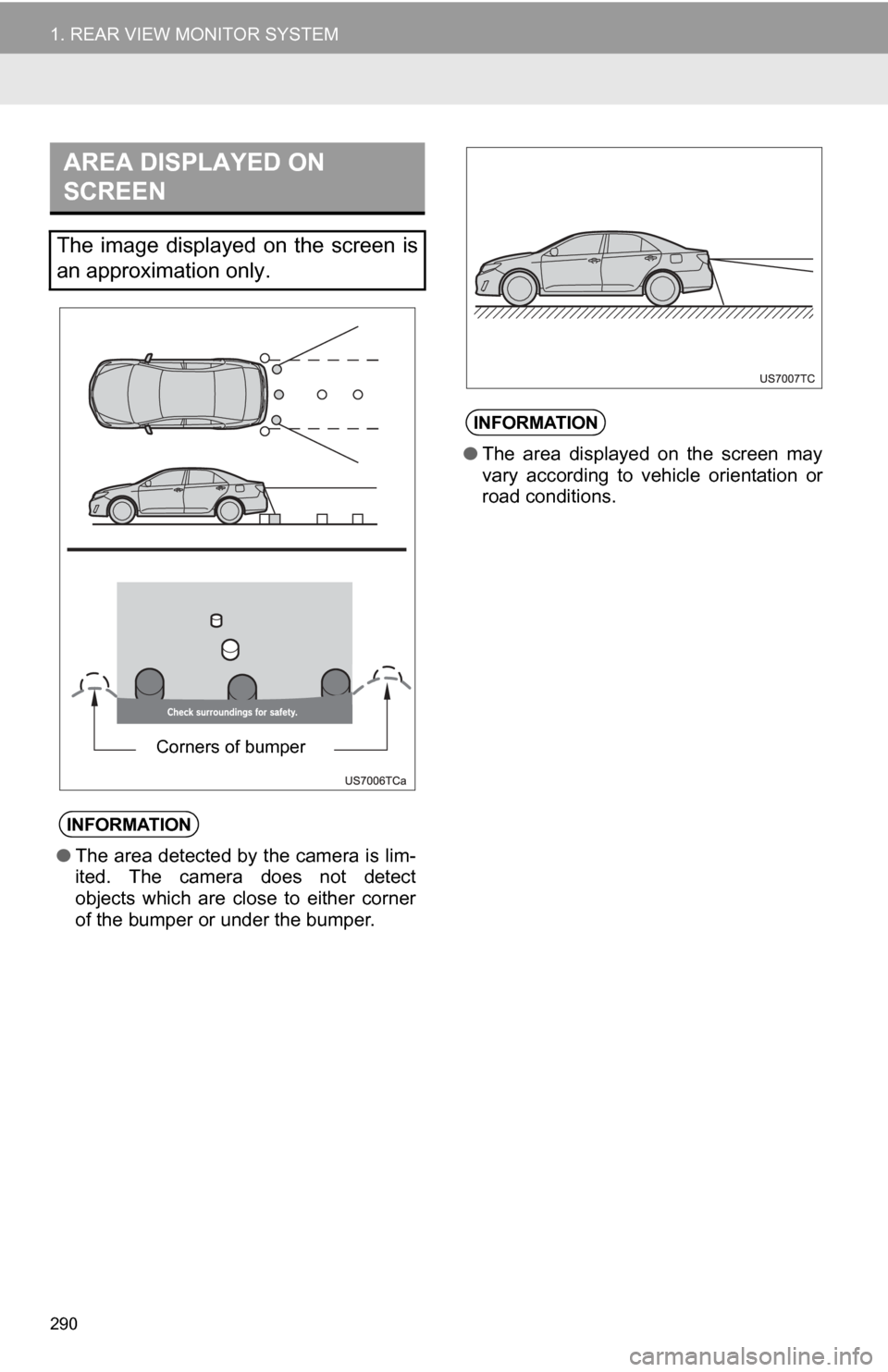
AREA DISPLAYED ON
SCREEN
The image displayed on the screen is
an approximation only.
INFORMATION
●The area detected by the camera is lim-
ited. The camera does not detect
objects which are close to either corner
of the bumper or under the bumper.
Corners of bumper
INFORMATION
●The area displayed on the screen may
vary according to vehicle orientation or
road conditions.