TOYOTA CAMRY V20 1986 Service Information
Manufacturer: TOYOTA, Model Year: 1986, Model line: CAMRY V20, Model: TOYOTA CAMRY V20 1986Pages: 2389, PDF Size: 84.44 MB
Page 1251 of 2389
26. INSTALL OIL PRESSURE SWITCH, ENGINE HANGERS
AND ALTERNATOR BRACKET
Torque the bolts.
Torque: 500 kg±cm (37 ft±Ib, 48 N±m)
27. INSTALL ALTERNATOR (See page CH±14)
28. INSTALL AIR CLEANER HOSE
29. INSTALL CRUISE CONTROL ACTUATOR
(See step 26 on page EM±137)
30. INSTALL RADIATOR RESERVOIR TANK
31. INSTALL ACCELERATOR CABLE, AND ADJUST IT
32. (A/T)
CONNECT THROTTLE CABLE, AND ADJUST IT
33. FILL WITH ENGINE COOLANT (See page CO±5)
Capacity (w/ Heater):
M/T 6.4 liters (6.8 US qts, 5.6 Imp. qts)
A/T (2WD) 6.3 liters (6.7 US qts, 5.5 Imp. qts)
A/T (4WD) 6.8 liters (7.2 US qts, 6.0 Imp. qts)
34. CONNECT CABLE TO NEGATIVE TERMINAL OF
BATTERY
35. START ENGINE AND CHECK FOR LEAKS
36. PERFORM ENGINE ADJUSTMENT
(a) Adjust the valve clearance. (See page EM±11)
Valve clearance (Cold):
Intake 0.19 ± 0.29 mm (0.007 ± 0.011 in.)
Exhaust 0.28 ± 0.38 mm (0.011 ± 0.015 in.)
(b) Adjust the ignition timing.
(See steps 7 to 10 on pages IG±16 and 17)
Ignition timing:
10° BTDC @ idle
(w/ Terminals TE 1 and E 1 connected)
37. CHECK TOE±IN (See page FA±5)
38. PERFORM ROAD TEST
Check for abnormal noise, shock, slippage, correct shift
points and smooth operation.
39. RECHECK ENGINE COOLANT LEVEL AND OIL LEVEL
± ENGINE MECHANICALCylinder Head (3S±FE)EM±74
Page 1252 of 2389
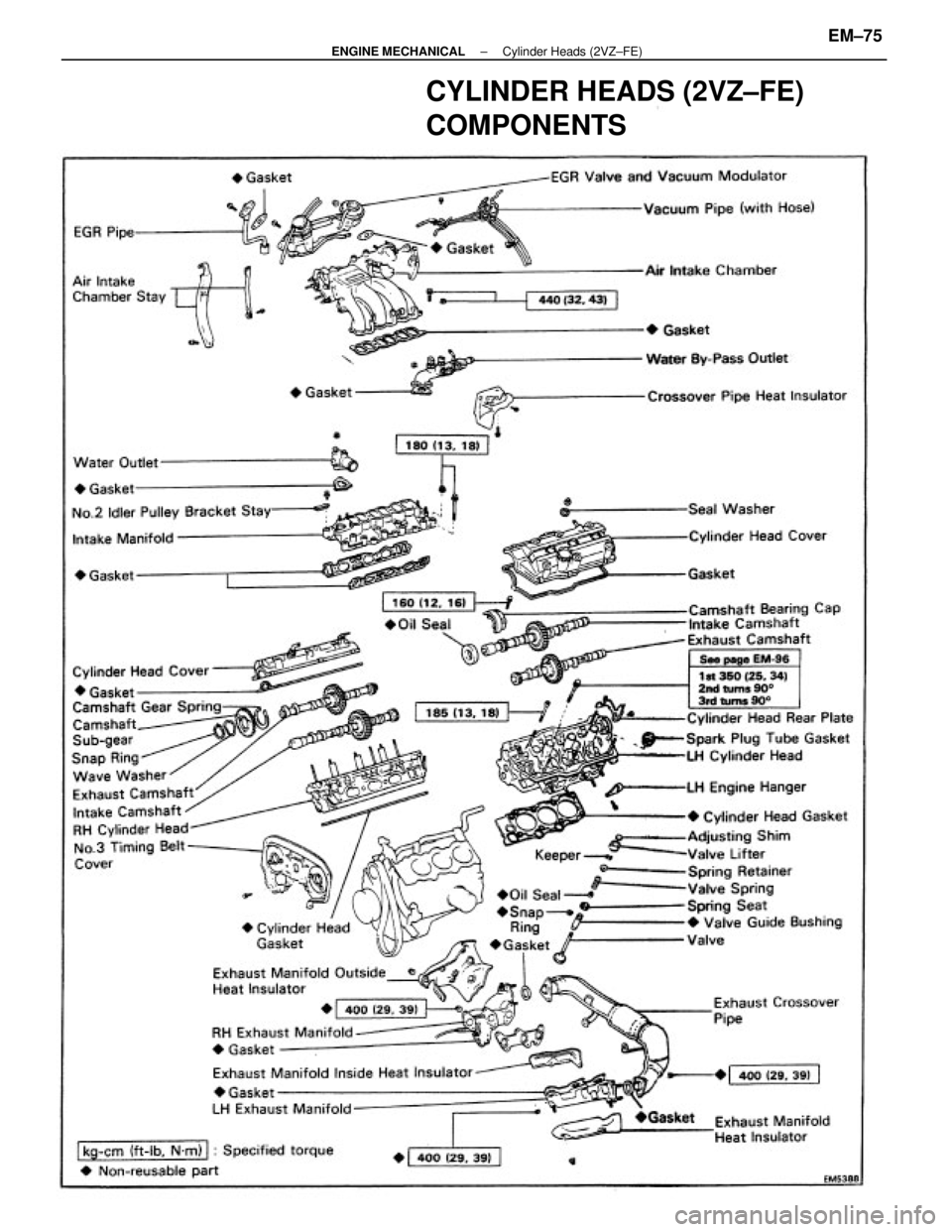
CYLINDER HEADS (2VZ±FE)
COMPONENTS
± ENGINE MECHANICALCylinder Heads (2VZ±FE)EM±75
Page 1253 of 2389
REMOVAL OF CYLINDER HEADS
(See page EM±75)
1. DISCONNECT CABLE FROM NEGATIVE TERMINAL
OF BATTERY
2. DRAIN ENGINE COOLANT (See page CO±5)
3. (A/T)
DISCONNECT THROTTLE CABLE FROM THROTTLE
BODY
4. DISCONNECT ACCELERATOR CABLE FROM
THROTTLE BODY
5. (w/ CRUISE CONTROL SYSTEM)
REMOVE CRUISE CONTROL ACTUATOR AND
VACUUM PUMP (See step 74 on page EM±140)
6. REMOVE AIR CLEANER HOSE
(a) Disconnect the following hoses:
(1) RSC valve air hose
(2) Vacuum pipe hose
(b) Remove the air cleaner hose.
7. RAISE VEHICLE
NOTICE: Be sure the vehicle is securely supported.
8. REMOVE ENGINE RH UNDER COVER
9. REMOVE SUSPENSION LOWER CROSSMEMBER
(See step 26 on page EM±142)
10. REMOVE FRONT EXHAUST PIPE
(See step 27 on page EM±142)
11. REMOVE ALTERNATOR (See page CH±7)
12. REMOVE ISC VALVE
(See steps 2 to 4 on pages Fl±118 and 119)
13. REMOVE THROTTLE BODY
(See steps 5 to 6 on page FI±113)
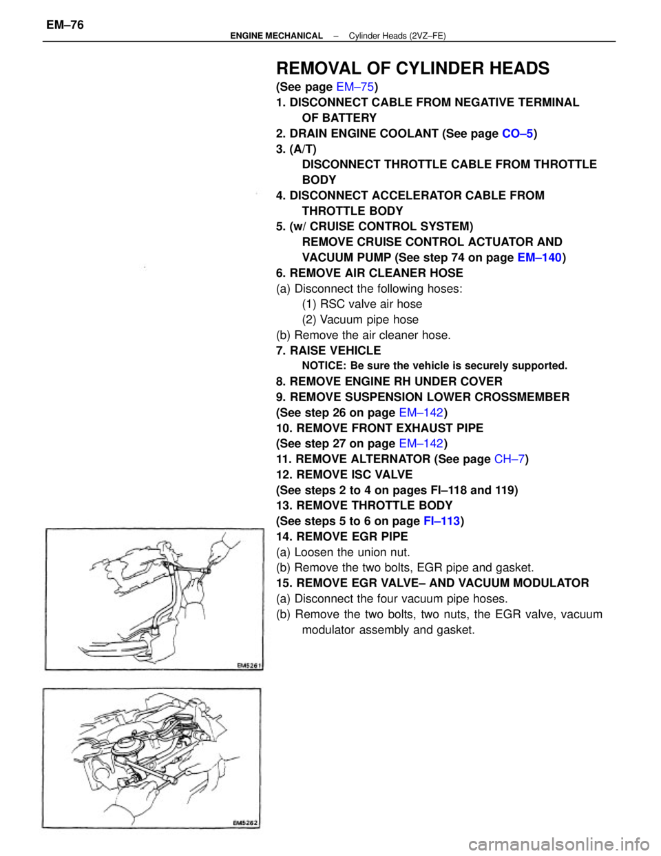
14. REMOVE EGR PIPE
(a) Loosen the union nut.
(b) Remove the two bolts, EGR pipe and gasket.
15. REMOVE EGR VALVE± AND VACUUM MODULATOR
(a) Disconnect the four vacuum pipe hoses.
(b) Remove the two bolts, two nuts, the EGR valve, vacuum
modulator assembly and gasket.
± ENGINE MECHANICALCylinder Heads (2VZ±FE)EM±76
Page 1254 of 2389

21. REMOVE AIR INTAKE CHAMBER
(a) Disconnect the following hoses:
(1) PCV hose
(2) Vacuum sensing hose
(3) Fuel pressure control VSV
(4) (Calif. only)
EGR gas temperature sensor connector
(5) A/C control valve vacuum hose
(b) Remove the four bolts and two intake chamber stays.
(c) Remove the two bolts, two nuts, intake chamber and two
gaskets.
22. REMOVE DELIVERY PIPES AND INJECTORS
(See steps 15 to 19 on pages FI±95 and 96) 18. REMOVE EXHAUST CROSSOVER PIPE
Remove the six nuts, two bolts, crossover pipe and two gas-
kets.
19. DISCONNECT COLD START INJECTOR CONNECTOR
20. REMOVE COLD START INJECTOR TUBE
(See step 3 on page FI±81) 16. REMOVE VACUUM PIPE
(a) Disconnect the following hoses:
(1) Four± BVSV vacuum hoses
(2) Fuel pressure control VSV hose
(3) A/C control valve vacuum hose
(b) Remove the two bolts and vacuum pipe.
17. REMOVE DISTRIBUTOR (See page IG±18)
23. REMOVE WATER OUTLET
(a) Disconnect the following connector and hose:
(1) Water temperature sensor connector
(2) Radiator upper hose
(b) Remove the three nuts, water outlet and gasket.
± ENGINE MECHANICALCylinder Heads (2VZ±FE)EM±77
Page 1255 of 2389
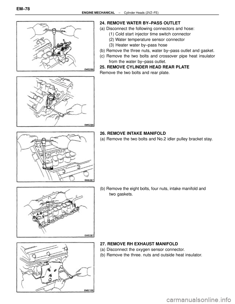
24. REMOVE WATER BY±PASS OUTLET
(a) Disconnect the following connectors and hose:
(1) Cold start injector time switch connector
(2) Water temperature sensor connector
(3) Heater water by±pass hose
(b) Remove the three nuts, water by±pass outlet and gasket.
(c) Remove the two bolts and crossover pipe heat insulator
from the water by±pass outlet.
25. REMOVE CYLINDER HEAD REAR PLATE
Remove the two bolts and rear plate.
27. REMOVE RH EXHAUST MANIFOLD
(a) Disconnect the oxygen sensor connector.
(b) Remove the three. nuts and outside heat insulator. 26. REMOVE INTAKE MANIFOLD
(a) Remove the two bolts and No.2 idler pulley bracket stay.
(b) Remove the eight bolts, four nuts, intake manifold and
two gaskets.
± ENGINE MECHANICALCylinder Heads (2VZ±FE)EM±78
Page 1256 of 2389
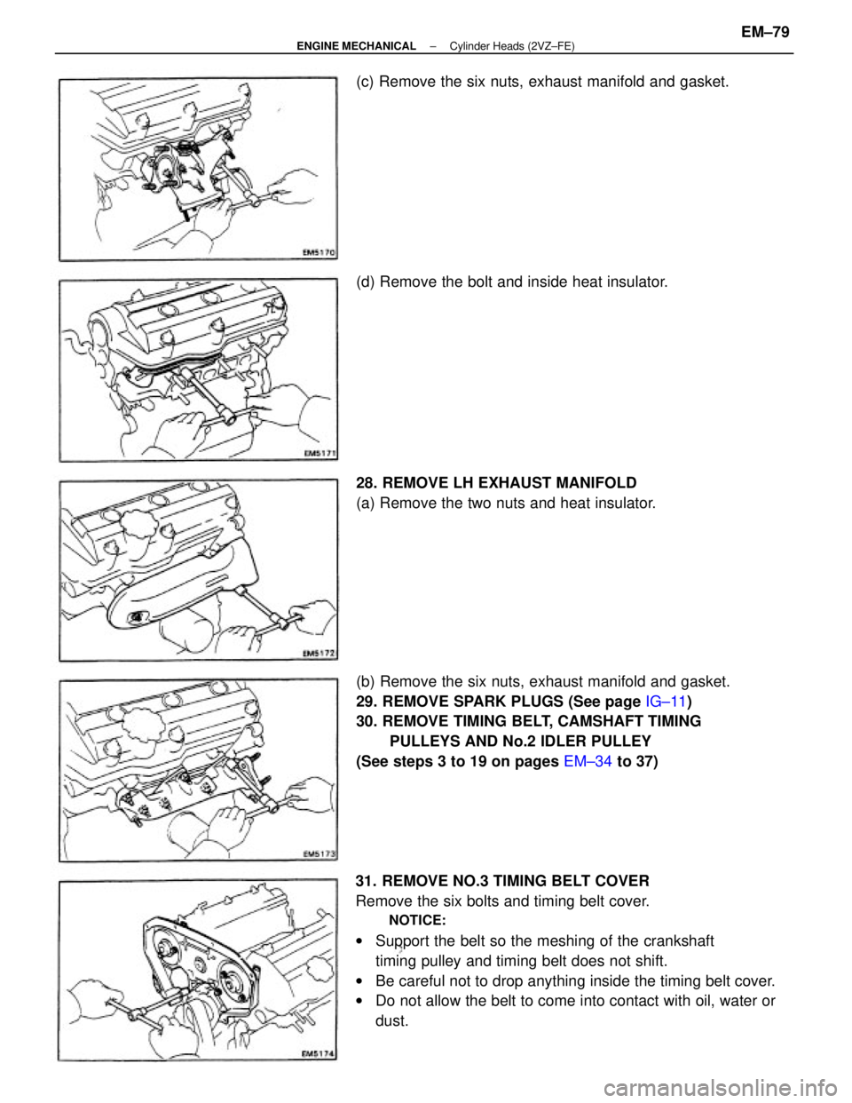
31. REMOVE NO.3 TIMING BELT COVER
Remove the six bolts and timing belt cover.
NOTICE:
wSupport the belt so the meshing of the crankshaft
timing pulley and timing belt does not shift.
wBe careful not to drop anything inside the timing belt cover.
wDo not allow the belt to come into contact with oil, water or
dust. (b) Remove the six nuts, exhaust manifold and gasket.
29. REMOVE SPARK PLUGS (See page IG±11)
30. REMOVE TIMING BELT, CAMSHAFT TIMING
PULLEYS AND No.2 IDLER PULLEY
(See steps 3 to 19 on pages EM±34 to 37) 28. REMOVE LH EXHAUST MANIFOLD
(a) Remove the two nuts and heat insulator. (c) Remove the six nuts, exhaust manifold and gasket.
(d) Remove the bolt and inside heat insulator.
± ENGINE MECHANICALCylinder Heads (2VZ±FE)EM±79
Page 1257 of 2389
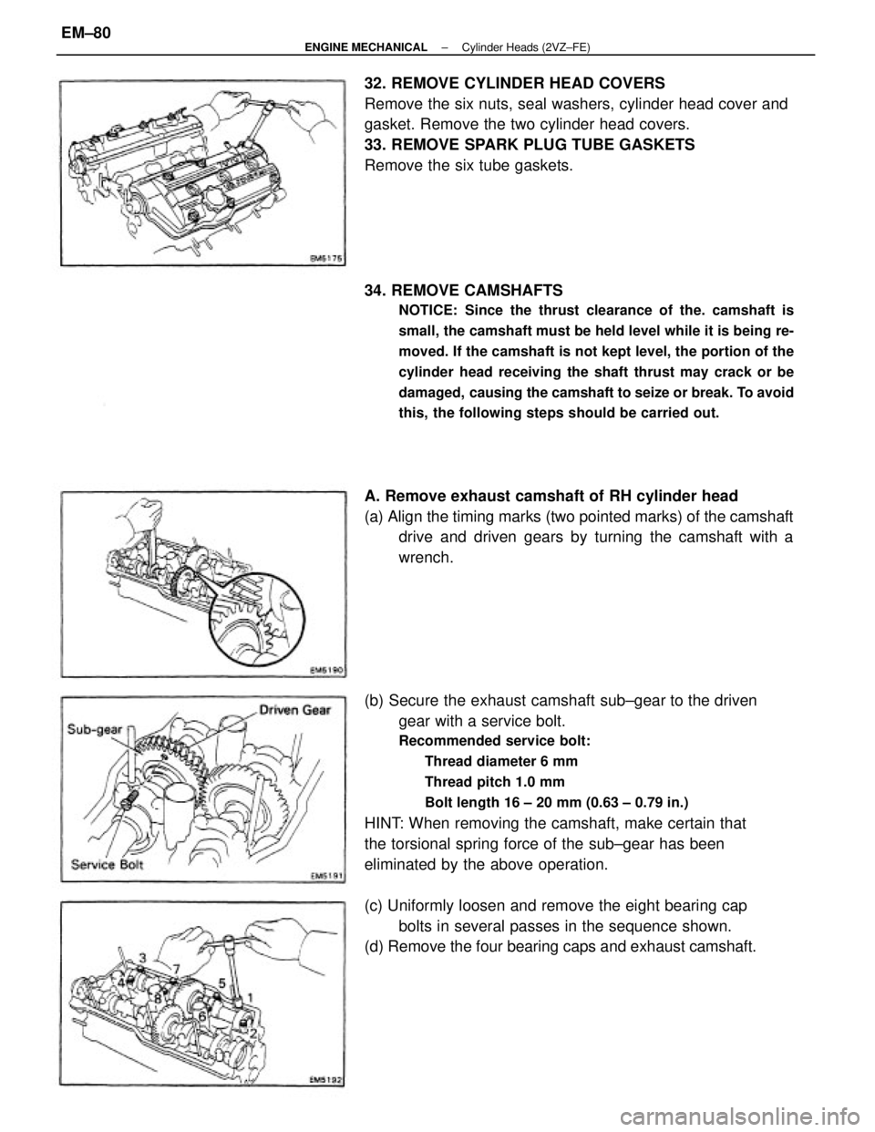
(b) Secure the exhaust camshaft sub±gear to the driven
gear with a service bolt.
Recommended service bolt:
Thread diameter 6 mm
Thread pitch 1.0 mm
Bolt length 16 ± 20 mm (0.63 ± 0.79 in.)
HINT: When removing the camshaft, make certain that
the torsional spring force of the sub±gear has been
eliminated by the above operation. 32. REMOVE CYLINDER HEAD COVERS
Remove the six nuts, seal washers, cylinder head cover and
gasket. Remove the two cylinder head covers.
33. REMOVE SPARK PLUG TUBE GASKETS
Remove the six tube gaskets.
34. REMOVE CAMSHAFTS
NOTICE: Since the thrust clearance of the. camshaft is
small, the camshaft must be held level while it is being re-
moved. If the camshaft is not kept level, the portion of the
cylinder head receiving the shaft thrust may crack or be
damaged, causing the camshaft to seize or break. To avoid
this, the following steps should be carried out.
A. Remove exhaust camshaft of RH cylinder head
(a) Align the timing marks (two pointed marks) of the camshaft
drive and driven gears by turning the camshaft with a
wrench.
(c) Uniformly loosen and remove the eight bearing cap
bolts in several passes in the sequence shown.
(d) Remove the four bearing caps and exhaust camshaft.
± ENGINE MECHANICALCylinder Heads (2VZ±FE)EM±80
Page 1258 of 2389
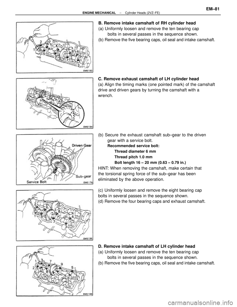
(b) Secure the exhaust camshaft sub±gear to the driven
gear with a service bolt.
Recommended service bolt:
Thread diameter 6 mm
Thread pitch 1.0 mm
Bolt length 16 ± 20 mm (0.63 ± 0.79 in.)
HINT: When removing the camshaft, make certain that
the torsional spring force of the sub±gear has been
eliminated by the above operation.
D. Remove intake camshaft of LH cylinder head
(a) Uniformly loosen and remove the ten bearing cap
bolts in several passes in the sequence shown.
(b) Remove the five bearing caps, oil seal and intake camshaft.B. Remove intake camshaft of RH cylinder head
(a) Uniformly loosen and remove the ten bearing cap
bolts in several passes in the sequence shown.
(b) Remove the five bearing caps, oil seal and intake camshaft.
C. Remove exhaust camshaft of LH cylinder head
(a) Align the timing marks (one pointed mark) of the camshaft
drive and driven gears by turning the camshaft with a
wrench.
(c) Uniformly loosen and remove the eight bearing cap
bolts in several passes in the sequence shown.
(d) Remove the four bearing caps and exhaust camshaft.
± ENGINE MECHANICALCylinder Heads (2VZ±FE)EM±81
Page 1259 of 2389
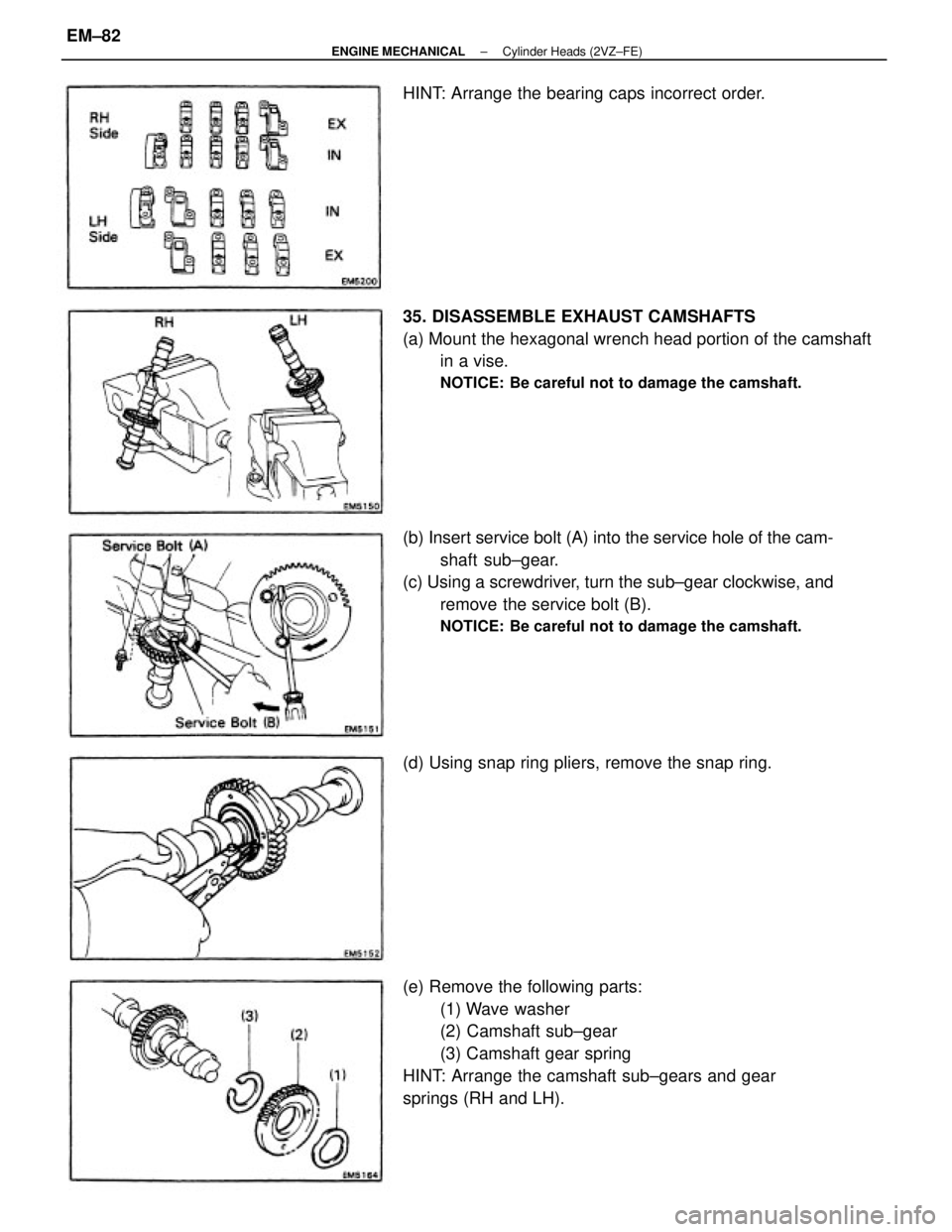
(e) Remove the following parts:
(1) Wave washer
(2) Camshaft sub±gear
(3) Camshaft gear spring
HINT: Arrange the camshaft sub±gears and gear
springs (RH and LH). (b) Insert service bolt (A) into the service hole of the cam-
shaft sub±gear.
(c) Using a screwdriver, turn the sub±gear clockwise, and
remove the service bolt (B).
NOTICE: Be careful not to damage the camshaft.
35. DISASSEMBLE EXHAUST CAMSHAFTS
(a) Mount the hexagonal wrench head portion of the camshaft
in a vise.
NOTICE: Be careful not to damage the camshaft.
(d) Using snap ring pliers, remove the snap ring. HINT: Arrange the bearing caps incorrect order.
± ENGINE MECHANICALCylinder Heads (2VZ±FE)EM±82
Page 1260 of 2389
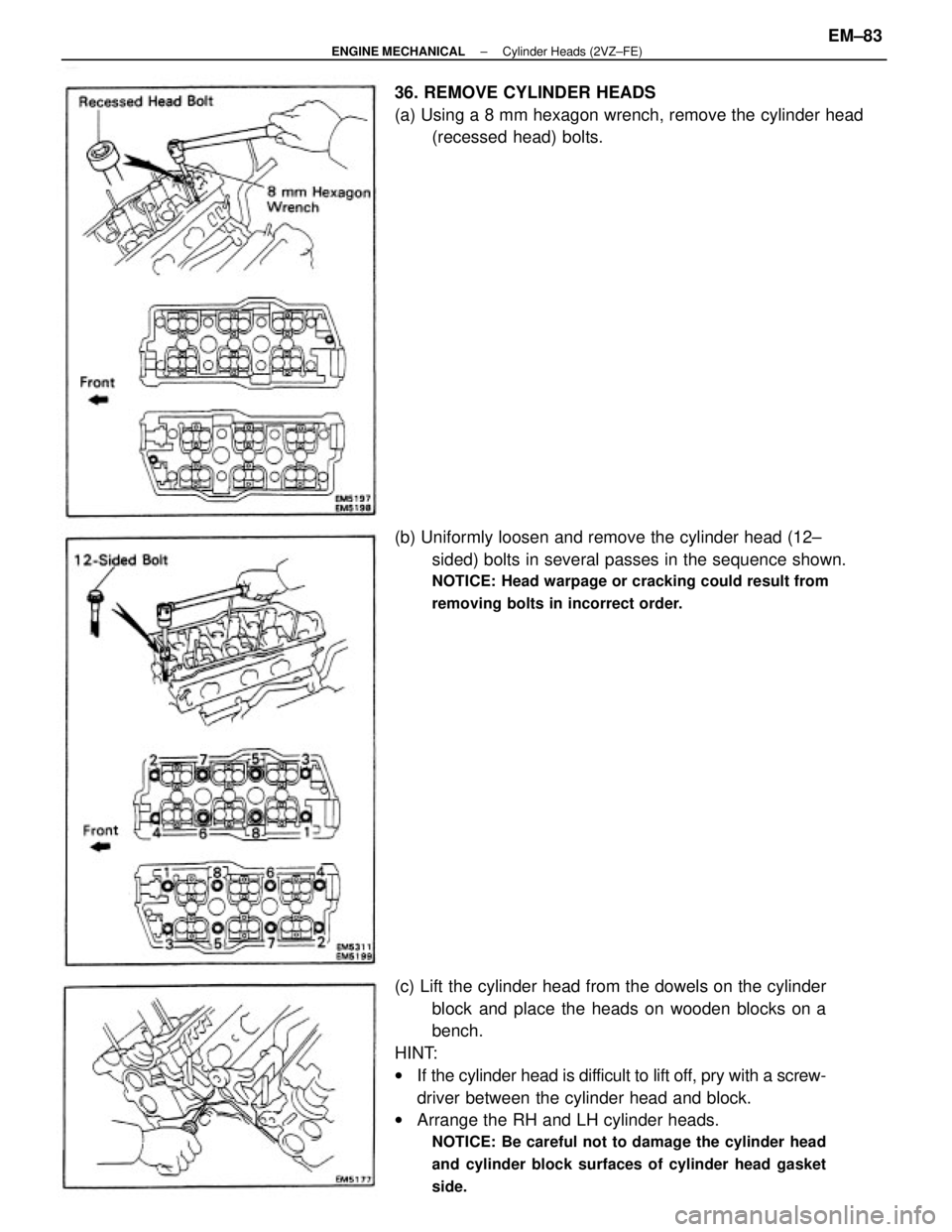
(c) Lift the cylinder head from the dowels on the cylinder
block and place the heads on wooden blocks on a
bench.
HINT:
wIf the cylinder head is difficult to lift off, pry with a screw-
driver between the cylinder head and block.
wArrange the RH and LH cylinder heads.
NOTICE: Be careful not to damage the cylinder head
and cylinder block surfaces of cylinder head gasket
side.
(b) Uniformly loosen and remove the cylinder head (12±
sided) bolts in several passes in the sequence shown.
NOTICE: Head warpage or cracking could result from
removing bolts in incorrect order.
36. REMOVE CYLINDER HEADS
(a) Using a 8 mm hexagon wrench, remove the cylinder head
(recessed head) bolts.
± ENGINE MECHANICALCylinder Heads (2VZ±FE)EM±83