TOYOTA CAMRY V20 1986 Service Information
Manufacturer: TOYOTA, Model Year: 1986, Model line: CAMRY V20, Model: TOYOTA CAMRY V20 1986Pages: 2389, PDF Size: 84.44 MB
Page 2381 of 2389
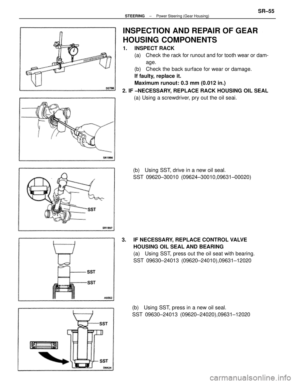
INSPECTION AND REPAIR OF GEAR
HOUSING COMPONENTS
1. INSPECT RACK
(a) Check the rack for runout and for tooth wear or dam-
age.
(b) Check the back surface for wear or damage.
If faulty, replace it.
Maximum runout: 0.3 mm (0.012 in.)
3. IF NECESSARY, REPLACE CONTROL VALVE
HOUSING OIL SEAL AND BEARING
(a) Using SST, press out the oil seat with bearing.
SST 09630±24013 (09620±24010),09631±12020 2. IF ±NECESSARY, REPLACE RACK HOUSING OIL SEAL
(a) Using a screwdriver, pry out the oil seai.
(b) Using SST, press in a new oil seal.
SST 09630±24013 (09620±24020),09631±12020(b) Using SST, drive in a new oil seal.
SST 09620±30010 (09624±30010,09631±00020)
± STEERINGPower Steering (Gear Housing)SR±55
Page 2382 of 2389
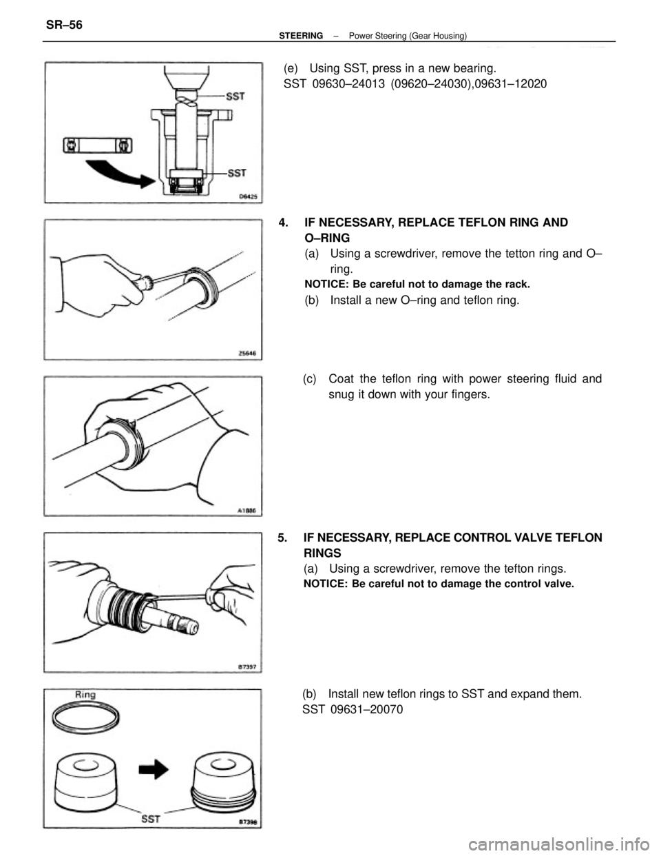
4. IF NECESSARY, REPLACE TEFLON RING AND
O±RING
(a) Using a screwdriver, remove the tetton ring and O±
ring.
NOTICE: Be careful not to damage the rack.
(b) Install a new O±ring and teflon ring.
5. IF NECESSARY, REPLACE CONTROL VALVE TEFLON
RINGS
(a) Using a screwdriver, remove the tefton rings.
NOTICE: Be careful not to damage the control valve.
(c) Coat the teflon ring with power steering fluid and
snug it down with your fingers. (e) Using SST, press in a new bearing.
SST 09630±24013 (09620±24030),09631±12020
(b) Install new teflon rings to SST and expand them.
SST 09631±20070
± STEERINGPower Steering (Gear Housing)SR±56
Page 2383 of 2389
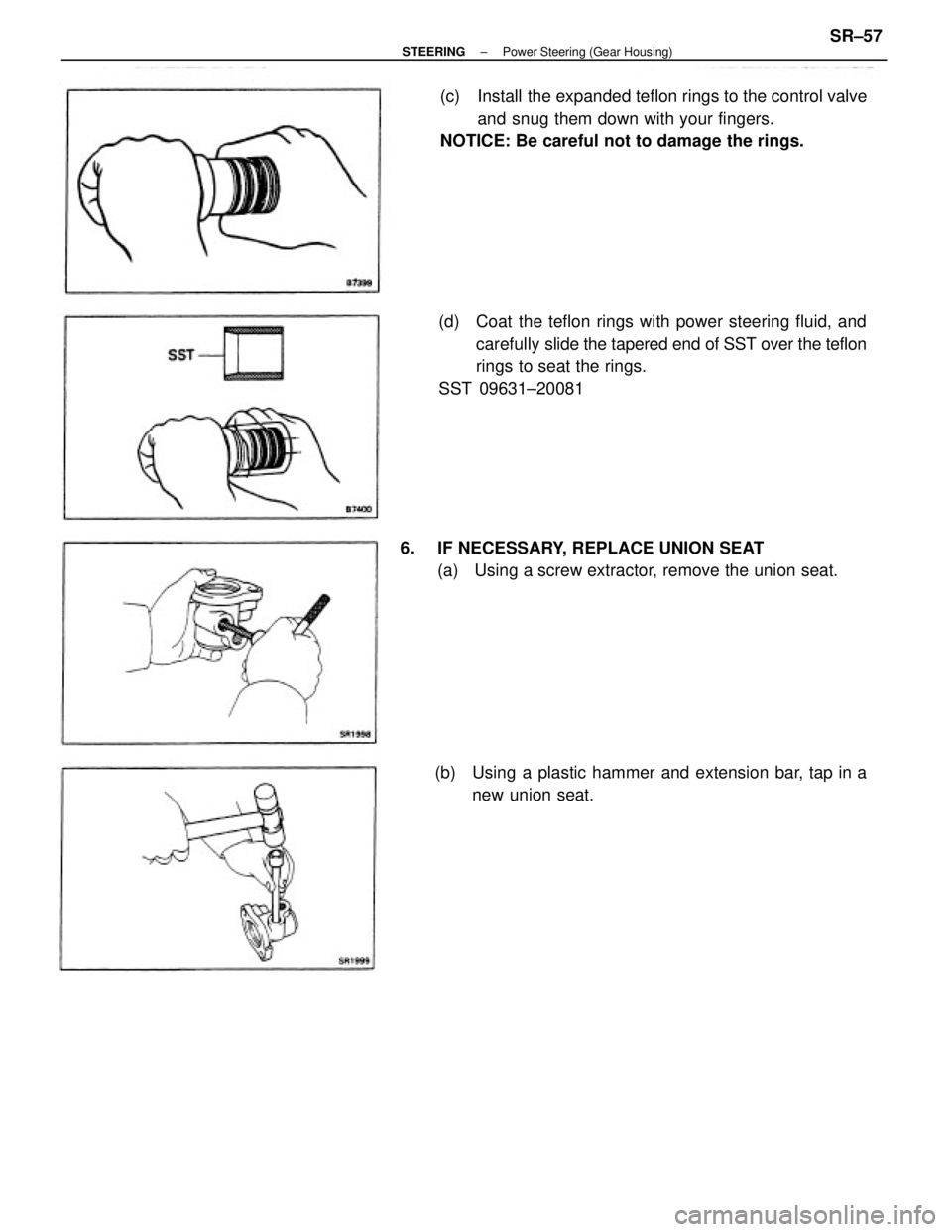
(d) Coat the teflon rings with power steering fluid, and
carefully slide the tapered end of SST over the teflon
rings to seat the rings.
SST 09631±20081(c) Install the expanded teflon rings to the control valve
and snug them down with your fingers.
NOTICE: Be careful not to damage the rings.
6. IF NECESSARY, REPLACE UNION SEAT
(a) Using a screw extractor, remove the union seat.
(b) Using a plastic hammer and extension bar, tap in a
new union seat.
± STEERINGPower Steering (Gear Housing)SR±57
Page 2384 of 2389
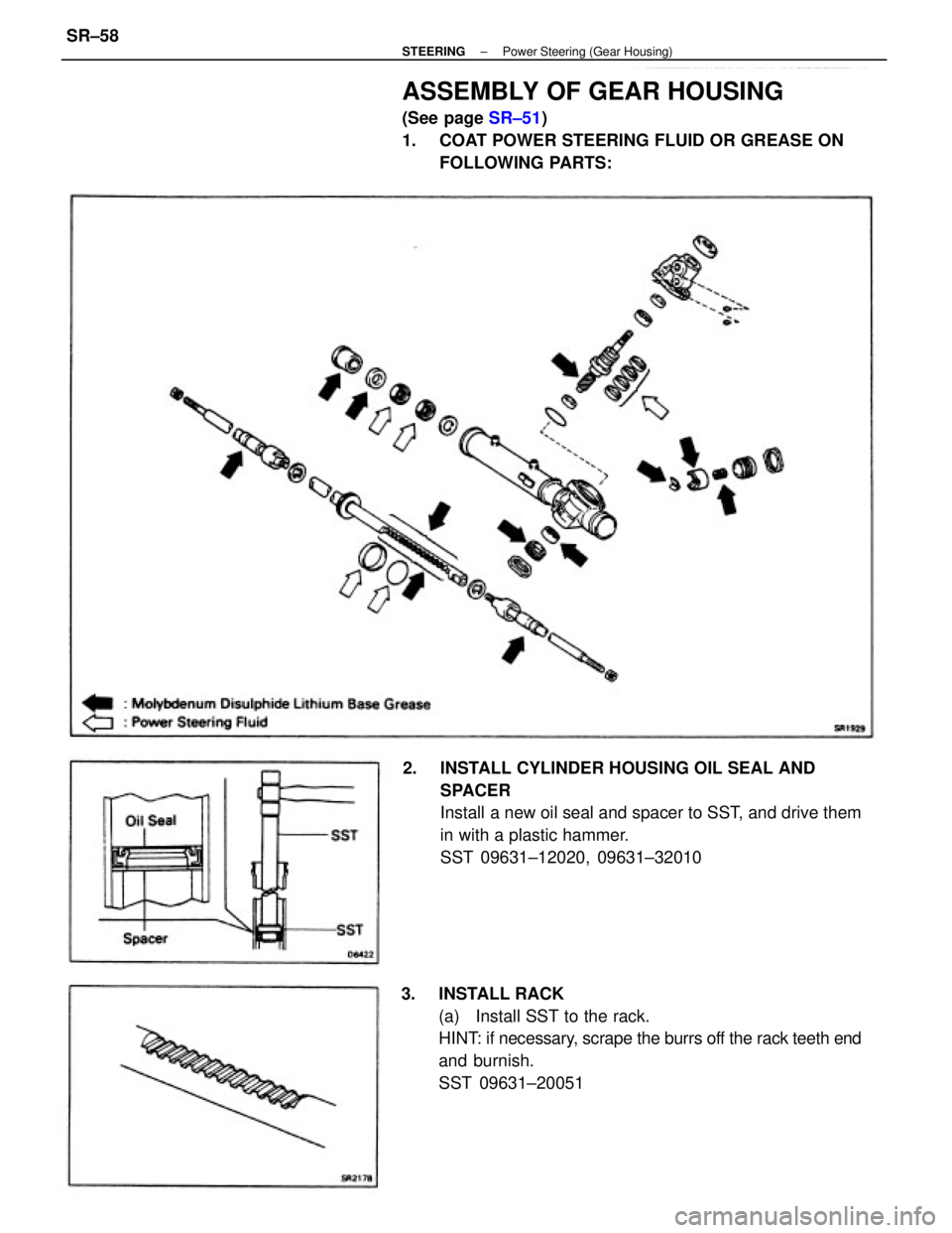
3. INSTALL RACK
(a) Install SST to the rack.
HINT: if necessary, scrape the burrs off the rack teeth end
and burnish.
SST 09631±20051 2. INSTALL CYLINDER HOUSING OIL SEAL AND
SPACER
Install a new oil seal and spacer to SST, and drive them
in with a plastic hammer.
SST 09631±12020, 09631±32010
ASSEMBLY OF GEAR HOUSING
(See page SR±51)
1. COAT POWER STEERING FLUID OR GREASE ON
FOLLOWING PARTS:
± STEERINGPower Steering (Gear Housing)SR±58
Page 2385 of 2389
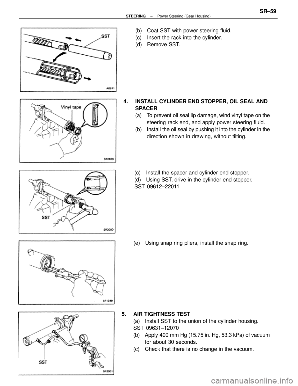
5. AIR TIGHTNESS TEST
(a) Install SST to the union of the cylinder housing.
SST 09631±12070
(b) Apply 400 mm Hg (15.75 in. Hg, 53.3 kPa) of vacuum
for about 30 seconds.
(c) Check that there is no change in the vacuum. 4. INSTALL CYLINDER END STOPPER, OIL SEAL AND
SPACER
(a) To prevent oil seal lip damage, wind vinyl tape on the
steering rack end, and apply power steering fluid.
(b) Install the oil seal by pushing it into the cylinder in the
direction shown in drawing, without tilting.
(c) Install the spacer and cylinder end stopper.
(d) Using SST, drive in the cylinder end stopper.
SST 09612±22011(b) Coat SST with power steering fluid.
(c) Insert the rack into the cylinder.
(d) Remove SST.
(e) Using snap ring pliers, install the snap ring.
± STEERINGPower Steering (Gear Housing)SR±59
Page 2386 of 2389
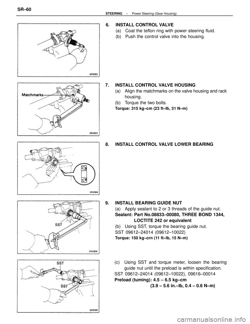
9. INSTALL BEARING GUIDE NUT
(a) Apply sealant to 2 or 3 threads of the guide nut.
Sealant: Part No.08833±00080, THREE BOND 1344,
LOCTITE 242 or equivalent
(b) Using SST, torque the bearing guide nut.
SST 09612±24014 (09612±10022)
Torque: 150 kg±crn (11 ft±Ib, 15 N±m)
7. INSTALL CONTROL VALVE HOUSING
(a) Align the matchmarks on the valve housing and rack
housing.
(b) Torque the two bolts.
Torque: 315 kg±cm (23 ft±Ib, 31 N±m)
(c) Using SST and torque meter, loosen the bearing
guide nut until the preload is within specification.
SST 09612±24014 (09612±10022), 09616±00014
Preload (tuming): 4.5 ± 6.5 kg±cm
(3.9 ± 5.6 in.±Ib, 0.4 ± 0.6 N±m) 6. INSTALL CONTROL VALVE
(a) Coat the teflon ring with power steering fluid.
(b) Push the control valve into the housing.
8. INSTALL CONTROL VALVE LOWER BEARING
± STEERINGPower Steering (Gear Housing)SR±60
Page 2387 of 2389
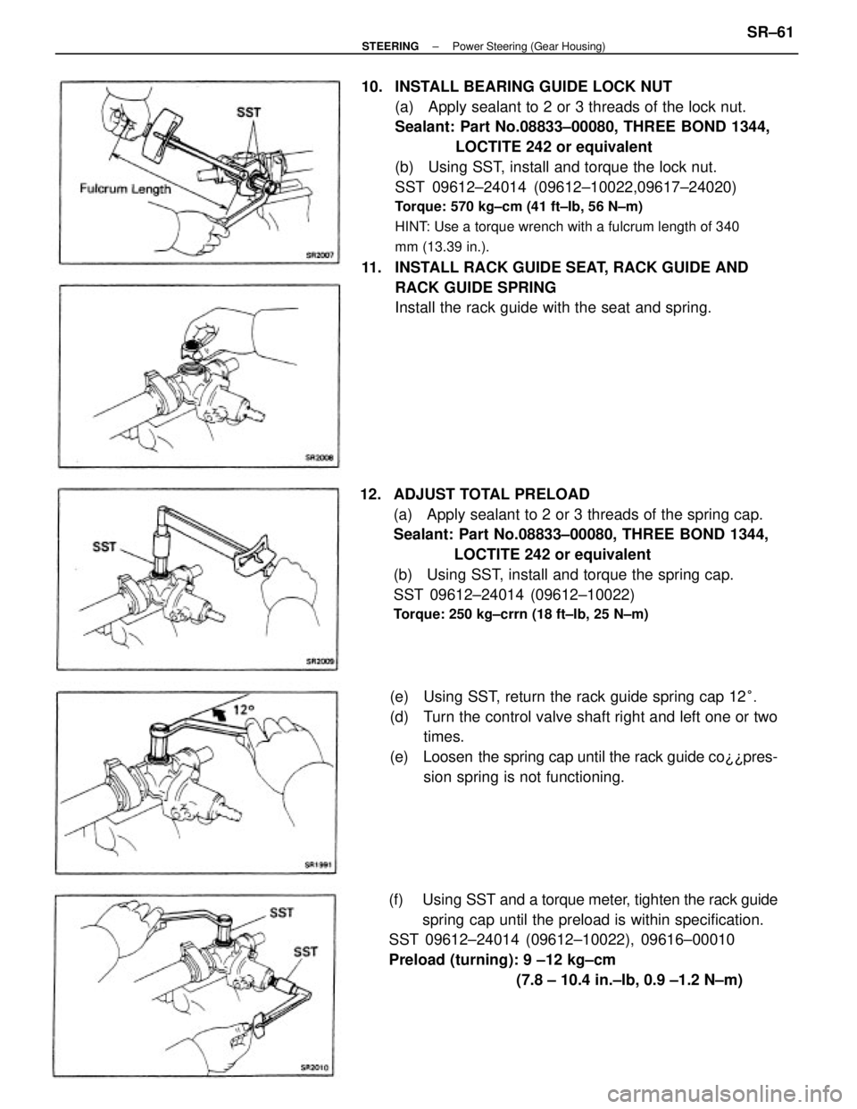
10. INSTALL BEARING GUIDE LOCK NUT
(a) Apply sealant to 2 or 3 threads of the lock nut.
Sealant: Part No.08833±00080, THREE BOND 1344,
LOCTITE 242 or equivalent
(b) Using SST, install and torque the lock nut.
SST 09612±24014 (09612±10022,09617±24020)
Torque: 570 kg±cm (41 ft±Ib, 56 N±m)
HINT: Use a torque wrench with a fulcrum length of 340
mm (13.39 in.).
11. INSTALL RACK GUIDE SEAT, RACK GUIDE AND
RACK GUIDE SPRING
Install the rack guide with the seat and spring.
12. ADJUST TOTAL PRELOAD
(a) Apply sealant to 2 or 3 threads of the spring cap.
Sealant: Part No.08833±00080, THREE BOND 1344,
LOCTITE 242 or equivalent
(b) Using SST, install and torque the spring cap.
SST 09612±24014 (09612±10022)
Torque: 250 kg±crrn (18 ft±Ib, 25 N±m)
(e) Using SST, return the rack guide spring cap 12°.
(d) Turn the control valve shaft right and left one or two
times.
(e) Loosen the spring cap until the rack guide co¿¿pres-
sion spring is not functioning.
(f) Using SST and a torque meter, tighten the rack guide
spring cap until the preload is within specification.
SST 09612±24014 (09612±10022), 09616±00010
Preload (turning): 9 ±12 kg±cm
(7.8 ± 10.4 in.±Ib, 0.9 ±1.2 N±m)
± STEERINGPower Steering (Gear Housing)SR±61
Page 2388 of 2389
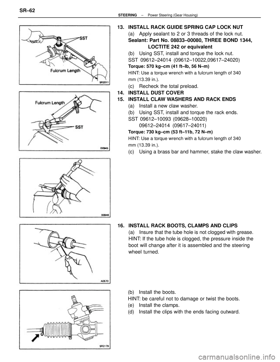
13. INSTALL RACK GUIDE SPRING CAP LOCK NUT
(a) Apply sealant to 2 or 3 threads of the lock nut.
Sealant: Part No. 08833±00080, THREE BOND 1344,
LOCTITE 242 or equivalent
(b) Using SST, install and torque the lock nut.
SST 09612±24014 (09612±10022,09617±24020)
Torque: 570 kg±cm (41 ft±Ib, 56 N±m)
HINT: Use a torque wrench with a fulcrum length of 340
mm (13.39 in.).
(c) Recheck the total preload.
14. INSTALL DUST COVER
15. INSTALL CLAW WASHERS AND RACK ENDS
(a) Install a new claw washer.
(b) Using SST, install and torque the rack ends.
SST 09612±10093 (09628±10020)
09612±24014 (09617±24011)
Torque: 730 kg±cm (53 ft±11b, 72 N±m)
HINT: Use a torque wrench with a fulcrum length of 340
mm (13.39 in.).
(c) Using a brass bar and hammer, stake the claw washer.
16. INSTALL RACK BOOTS, CLAMPS AND CLIPS
(a) Insure that the tube hole is not clogged with grease.
HINT: If the tube hole is clogged, the pressure inside the
boot will change after it is assembled and the steering
wheel turned.
(b) Install the boots.
HINT: be careful not to damage or twist the boots.
(e) Install the clamps.
(d) Install the clips with the ends facing outward.
± STEERINGPower Steering (Gear Housing)SR±62
Page 2389 of 2389
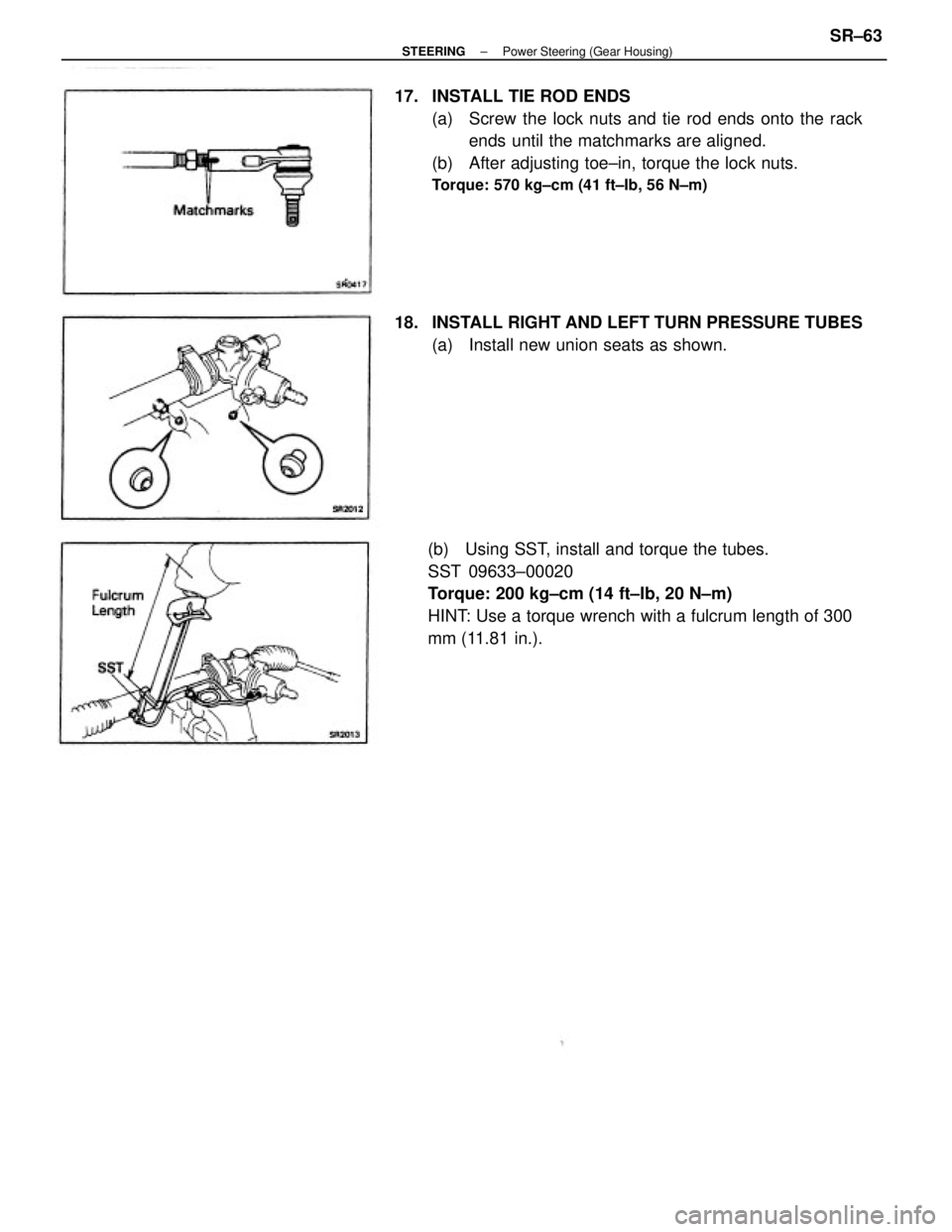
17. INSTALL TIE ROD ENDS
(a) Screw the lock nuts and tie rod ends onto the rack
ends until the matchmarks are aligned.
(b) After adjusting toe±in, torque the lock nuts.
Torque: 570 kg±cm (41 ft±Ib, 56 N±m)
(b) Using SST, install and torque the tubes.
SST 09633±00020
Torque: 200 kg±cm (14 ft±Ib, 20 N±m)
HINT: Use a torque wrench with a fulcrum length of 300
mm (11.81 in.). 18. INSTALL RIGHT AND LEFT TURN PRESSURE TUBES
(a) Install new union seats as shown.
± STEERINGPower Steering (Gear Housing)SR±63