ac relay replace TOYOTA CAMRY V20 1986 Service Information
[x] Cancel search | Manufacturer: TOYOTA, Model Year: 1986, Model line: CAMRY V20, Model: TOYOTA CAMRY V20 1986Pages: 2389, PDF Size: 84.44 MB
Page 771 of 2389
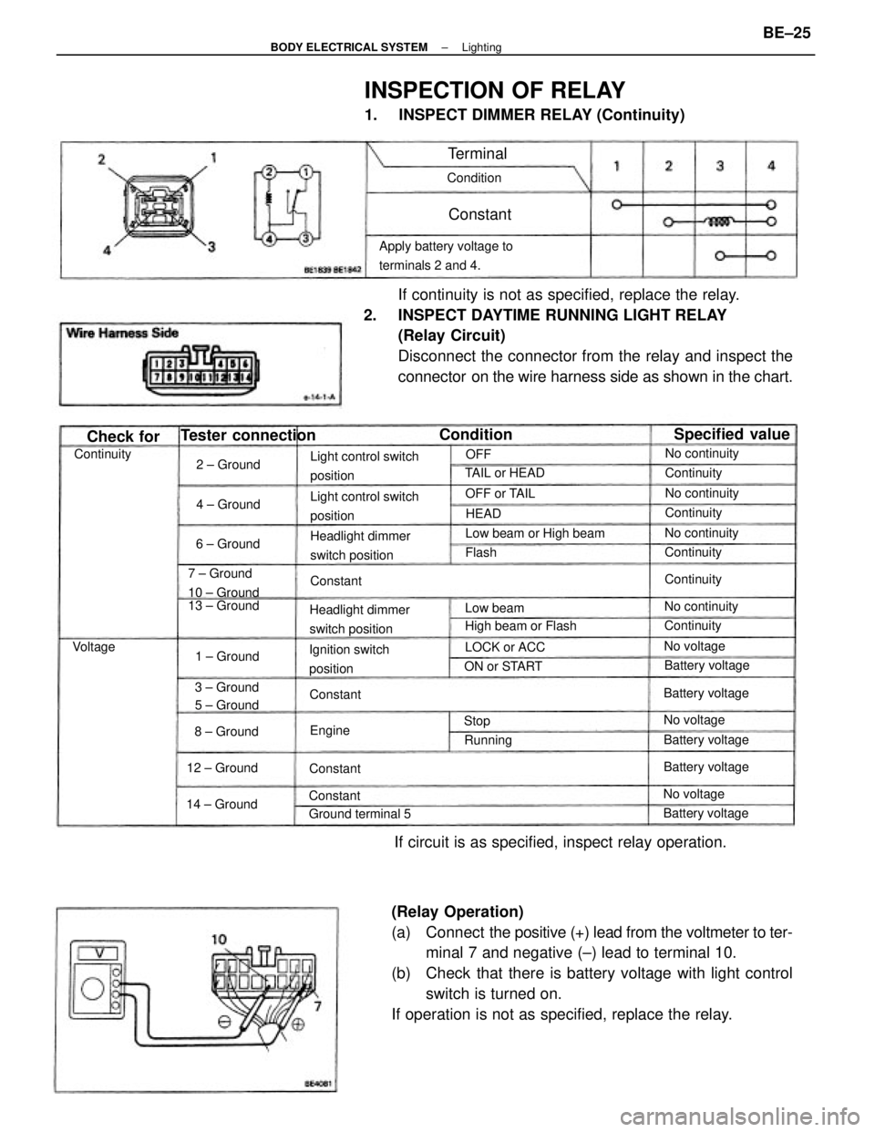
(Relay Operation)
(a) Connect the positive (+) lead from the voltmeter to ter-
minal 7 and negative (±) lead to terminal 10.
(b) Check that there is battery voltage with light control
switch is turned on.
If operation is not as specified, replace the relay.If continuity is not as specified, replace the relay.
2. INSPECT DAYTIME RUNNING LIGHT RELAY
(Relay Circuit)
Disconnect the connector from the relay and inspect the
connector on the wire harness side as shown in the chart.
INSPECTION OF RELAY
1. INSPECT DIMMER RELAY (Continuity)
If circuit is as specified, inspect relay operation.
Apply battery voltage to
terminals 2 and 4.
Light control switch
position
Light control switch
position
Headlight dimmer
switch positionHeadlight dimmer
switch positionLow beam or High beam
Ignition switch
position 7 ± Ground
10 ± Ground
High beam or Flash 13 ± Ground
3 ± Ground
5 ± Ground
Tester connection
Ground terminal 5
Specified value
Battery voltageBattery voltageBattery voltage
Battery voltage Battery voltageNo continuity
No continuity TAIL or HEADNo continuity
No continuity
14 ± Ground12 ± GroundON or STARTLOCK or ACC
1 ± GroundOFF or TAIL
8 ± Ground2 ± Ground
6 ± Ground4 ± Ground
No voltage
No voltage
No voltageContinuity
Continuity Continuity
Continuity
ContinuityContinuity
Condition
Check for
Low beam Condition
Running
Terminal
Constant
Constant
Constant
Constant
Constant Voltage
EngineHEAD
Flash
StopOFF
± BODY ELECTRICAL SYSTEMLightingBE±25
Page 772 of 2389
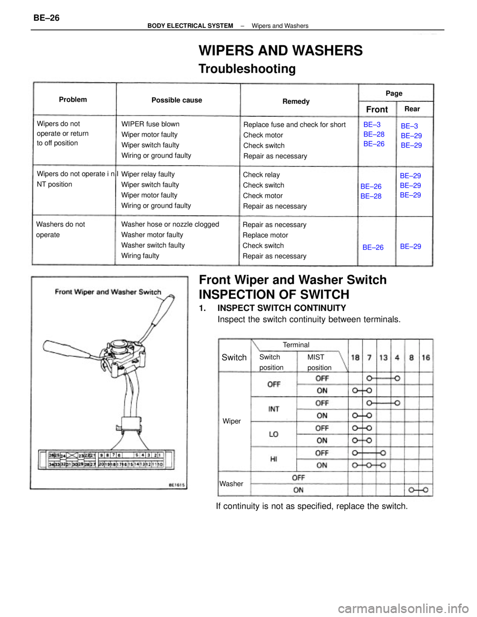
Front Wiper and Washer Switch
INSPECTION OF SWITCH
1. INSPECT SWITCH CONTINUITY
Inspect the switch continuity between terminals.
WIPERS AND WASHERS
Troubleshooting
Replace fuse and check for short
Check motor
Check switch
Repair as necessary
Washer hose or nozzle clogged
Washer motor faulty
Washer switch faulty
Wiring faultyWIPER fuse blown
Wiper motor faulty
Wiper switch faulty
Wiring or ground faulty
Wiper relay faulty
Wiper switch faulty
Wiper motor faulty
Wiring or ground faulty
Repair as necessary
Replace motor
Check switch
Repair as necessaryCheck relay
Check switch
Check motor
Repair as necessary
If continuity is not as specified, replace the switch.
Wipers do not
operate or return
to off position
Wipers do not operate i n I
NT position
Washers do not
operateBE±29
BE±29
BE±29BE±3
BE±29
BE±29 BE±3
BE±28
BE±26 Possible cause
BE±26
BE±28
Switch
positionMIST
position Terminal Remedy Problem
Washer
Switch
WiperBE±26BE±29 Page
FrontRear
± BODY ELECTRICAL SYSTEMWipers and WashersBE±26
Page 775 of 2389
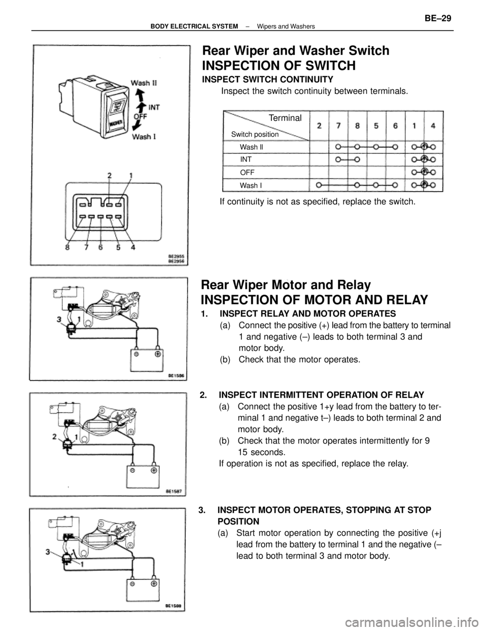
Rear Wiper Motor and Relay
INSPECTION OF MOTOR AND RELAY
1. INSPECT RELAY AND MOTOR OPERATES
(a) Connect the positive (+) lead from the battery to terminal
1 and negative (±) leads to both terminal 3 and
motor body.
(b) Check that the motor operates.
2. INSPECT INTERMITTENT OPERATION OF RELAY
(a) Connect the positive 1+y lead from the battery to ter-
minal 1 and negative t±) leads to both terminal 2 and
motor body.
(b) Check that the motor operates intermittently for 9
15 seconds.
If operation is not as specified, replace the relay.
3. INSPECT MOTOR OPERATES, STOPPING AT STOP
POSITION
(a) Start motor operation by connecting the positive (+j
lead from the battery to terminal 1 and the negative (±
lead to both terminal 3 and motor body.
Rear Wiper and Washer Switch
INSPECTION OF SWITCH
INSPECT SWITCH CONTINUITY
Inspect the switch continuity between terminals.
If continuity is not as specified, replace the switch.
Switch position
Terminal
Wash ll
Wash IOFF INT
± BODY ELECTRICAL SYSTEMWipers and WashersBE±29
Page 777 of 2389
Replace fuse and check for short
Replace bulb
Check switch
Check switch
Check switch
Check relay
Repair a s necessary ºDOMEº fuse blown
Bulb burned out
Door courtesy switch faulty
Unlock warning switch faulty
Buckle switch faulty
Seat belt warning relay faulty
Wiring or ground faultyºGAUGEº fuse blown
Bulb burned out
Brake fluid level warning switch faulty
Parking brake switch faulty
Wiring or ground faultyReplace fuse and check for short
Replace bulb
Check switch
Check switch
Repair as necessary ºGAUGEº fuse blown
Water temperature gauge faulty
Water temperature sender gauge faulty
Wiring or ground faulty
ºGAUGEº fuse blown
Buibburned out
oil pressure warning switch faulty
Wiring or ground faultyºGAUGEº fuse blown
Bulb burned out
Fuel level warning switch faulty
Wiring or ground faulty
Replace fuse and check for short
Replace bulb
Check switch
±Repair as necessaryReplace fuse and check for short
Replace bulb
Check switch
Repair as necessary
Replace fuse and check for short
Replace bulb
Check switch
Repair as necessaryReplace fuse and check for short
Check gauge
Check sender gauge
Repair as necessaryReplace fuse .and check for short
Check gauge
Check sender gauge
Repair as necessary
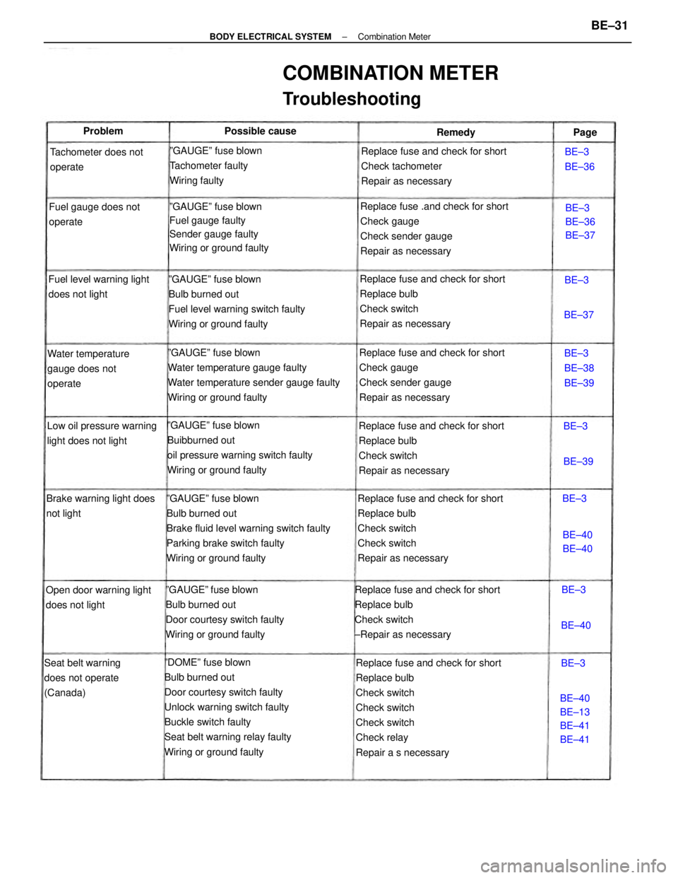
COMBINATION METER
Troubleshooting
ºGAUGEº fuse blown
Bulb burned out
Door courtesy switch faulty
Wiring or ground faultyReplace fuse and check for short
Check tachometer
Repair as necessary
ºGAUGEº fuse blown
Fuel gauge faulty
Sender gauge faulty
Wiring or ground faultyºGAUGEº fuse blown
Tachometer faulty
Wiring faulty
Low oil pressure warning
light does not lightWater temperature
gauge does not
operate
Seat belt warning
does not operate
(Canada)Tachometer does not
operate
Brake warning light does
not lightFuel gauge does not
operate
Open door warning light
does not lightFuel level warning light
does not light
BE±40
BE±13
BE±41
BE±41BE±3
BE±38
BE±39BE±3
BE±36
BE±37 Possible cause
BE±3
BE±36
BE±40
BE±40 Problem
Remedy
BE±40BE±39BE±37Page
BE±3BE±3
BE±3
BE±3
BE±3
± BODY ELECTRICAL SYSTEMCombination MeterBE±31
Page 787 of 2389
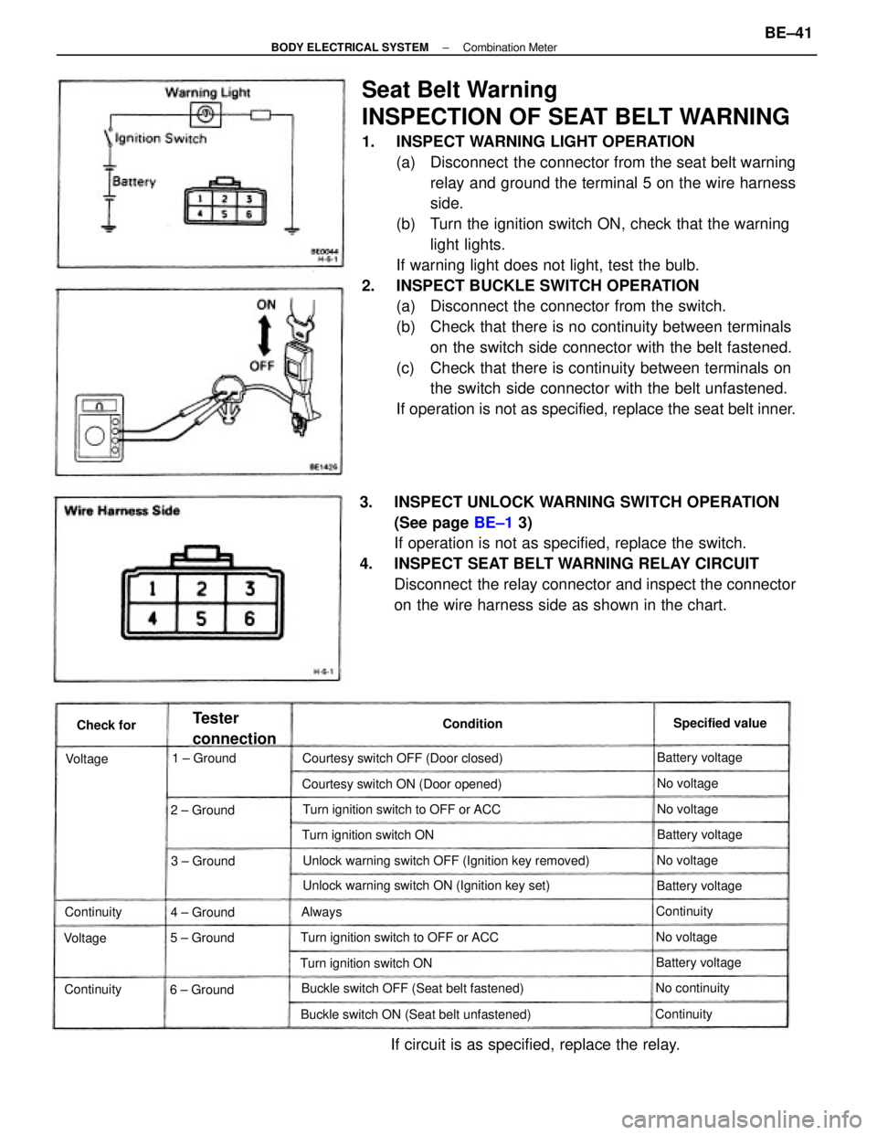
Seat Belt Warning
INSPECTION OF SEAT BELT WARNING
1. INSPECT WARNING LIGHT OPERATION
(a) Disconnect the connector from the seat belt warning
relay and ground the terminal 5 on the wire harness
side.
(b) Turn the ignition switch ON, check that the warning
light lights.
If warning light does not light, test the bulb.
2. INSPECT BUCKLE SWITCH OPERATION
(a) Disconnect the connector from the switch.
(b) Check that there is no continuity between terminals
on the switch side connector with the belt fastened.
(c) Check that there is continuity between terminals on
the switch side connector with the belt unfastened.
If operation is not as specified, replace the seat belt inner.
3. INSPECT UNLOCK WARNING SWITCH OPERATION
(See page BE±1 3)
If operation is not as specified, replace the switch.
4. INSPECT SEAT BELT WARNING RELAY CIRCUIT
Disconnect the relay connector and inspect the connector
on the wire harness side as shown in the chart.
Unlock warning switch OFF (Ignition key removed)
If circuit is as specified, replace the relay.
Unlock warning switch ON (Ignition key set)
Buckle switch ON (Seat belt unfastened)Buckle switch OFF (Seat belt fastened)Courtesy switch ON (Door opened)
Turn ignition switch to OFF or ACCTurn ignition switch to OFF or ACC Courtesy switch OFF (Door closed)
Turn ignition switch ONTurn ignition switch ON
6 ± Ground
Tester
connectionSpecified value
Battery voltage
Battery voltage
Battery voltageBattery voltage
No continuity 1 ± Ground
2 ± Ground
3 ± Ground
5 ± Ground4 ± GroundContinuity
Continuity
ContinuityNo voltageNo voltageNo voltage
No voltage
Continuity Condition
Check for
VoltageVoltage
Always
± BODY ELECTRICAL SYSTEMCombination MeterBE±41
Page 788 of 2389
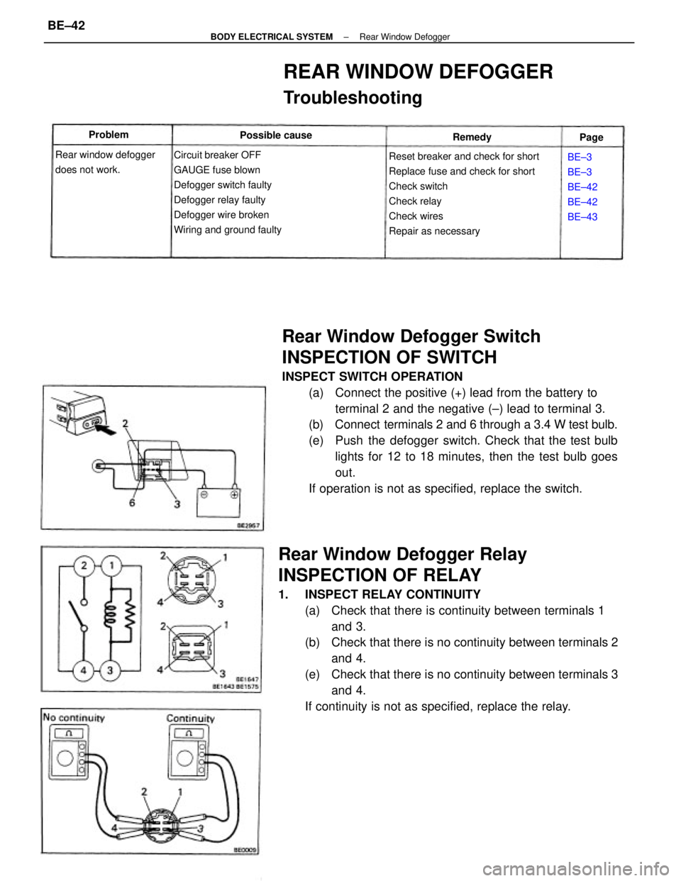
Rear Window Defogger Switch
INSPECTION OF SWITCH
INSPECT SWITCH OPERATION
(a) Connect the positive (+) lead from the battery to
terminal 2 and the negative (±) lead to terminal 3.
(b) Connect terminals 2 and 6 through a 3.4 W test bulb.
(e) Push the defogger switch. Check that the test bulb
lights for 12 to 18 minutes, then the test bulb goes
out.
If operation is not as specified, replace the switch.
Rear Window Defogger Relay
INSPECTION OF RELAY
1. INSPECT RELAY CONTINUITY
(a) Check that there is continuity between terminals 1
and 3.
(b) Check that there is no continuity between terminals 2
and 4.
(e) Check that there is no continuity between terminals 3
and 4.
If continuity is not as specified, replace the relay.
Reset breaker and check for short
Replace fuse and check for short
Check switch
Check relay
Check wires
Repair as necessary
REAR WINDOW DEFOGGER
Troubleshooting
Circuit breaker OFF
GAUGE fuse blown
Defogger switch faulty
Defogger relay faulty
Defogger wire broken
Wiring and ground faulty Rear window defogger
does not work.BE±3
BE±3
BE±42
BE±42
BE±43 Possible cause Problem
Remedy
Page
± BODY ELECTRICAL SYSTEMRear Window DefoggerBE±42
Page 789 of 2389
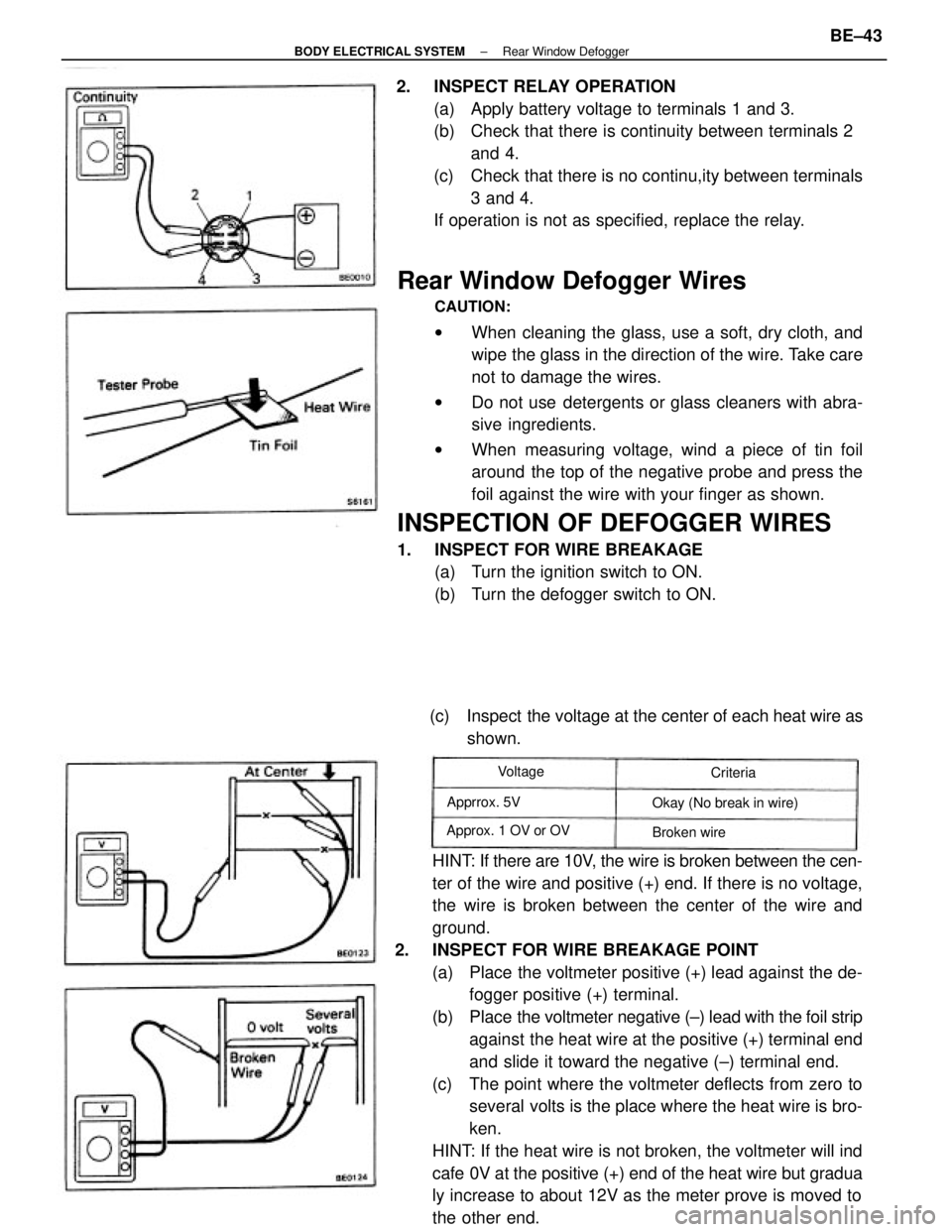
Rear Window Defogger Wires
CAUTION:
wWhen cleaning the glass, use a soft, dry cloth, and
wipe the glass in the direction of the wire. Take care
not to damage the wires.
wDo not use detergents or glass cleaners with abra-
sive ingredients.
wWhen measuring voltage, wind a piece of tin foil
around the top of the negative probe and press the
foil against the wire with your finger as shown.
INSPECTION OF DEFOGGER WIRES
1. INSPECT FOR WIRE BREAKAGE
(a) Turn the ignition switch to ON.
(b) Turn the defogger switch to ON.
HINT: If there are 10V, the wire is broken between the cen-
ter of the wire and positive (+) end. If there is no voltage,
the wire is broken between the center of the wire and
ground.
2. INSPECT FOR WIRE BREAKAGE POINT
(a) Place the voltmeter positive (+) lead against the de-
fogger positive (+) terminal.
(b) Place the voltmeter negative (±) lead with the foil strip
against the heat wire at the positive (+) terminal end
and slide it toward the negative (±) terminal end.
(c) The point where the voltmeter deflects from zero to
several volts is the place where the heat wire is bro-
ken.
HINT: If the heat wire is not broken, the voltmeter will ind
cafe 0V at the positive (+) end of the heat wire but gradua
ly increase to about 12V as the meter prove is moved to
the other end. 2. INSPECT RELAY OPERATION
(a) Apply battery voltage to terminals 1 and 3.
(b) Check that there is continuity between terminals 2
and 4.
(c) Check that there is no continu,ity between terminals
3 and 4.
If operation is not as specified, replace the relay.
(c) Inspect the voltage at the center of each heat wire as
shown.
Okay (No break in wire)
Approx. 1 OV or OVApprrox. 5V
Broken wire Voltage
Criteria
± BODY ELECTRICAL SYSTEMRear Window DefoggerBE±43
Page 793 of 2389
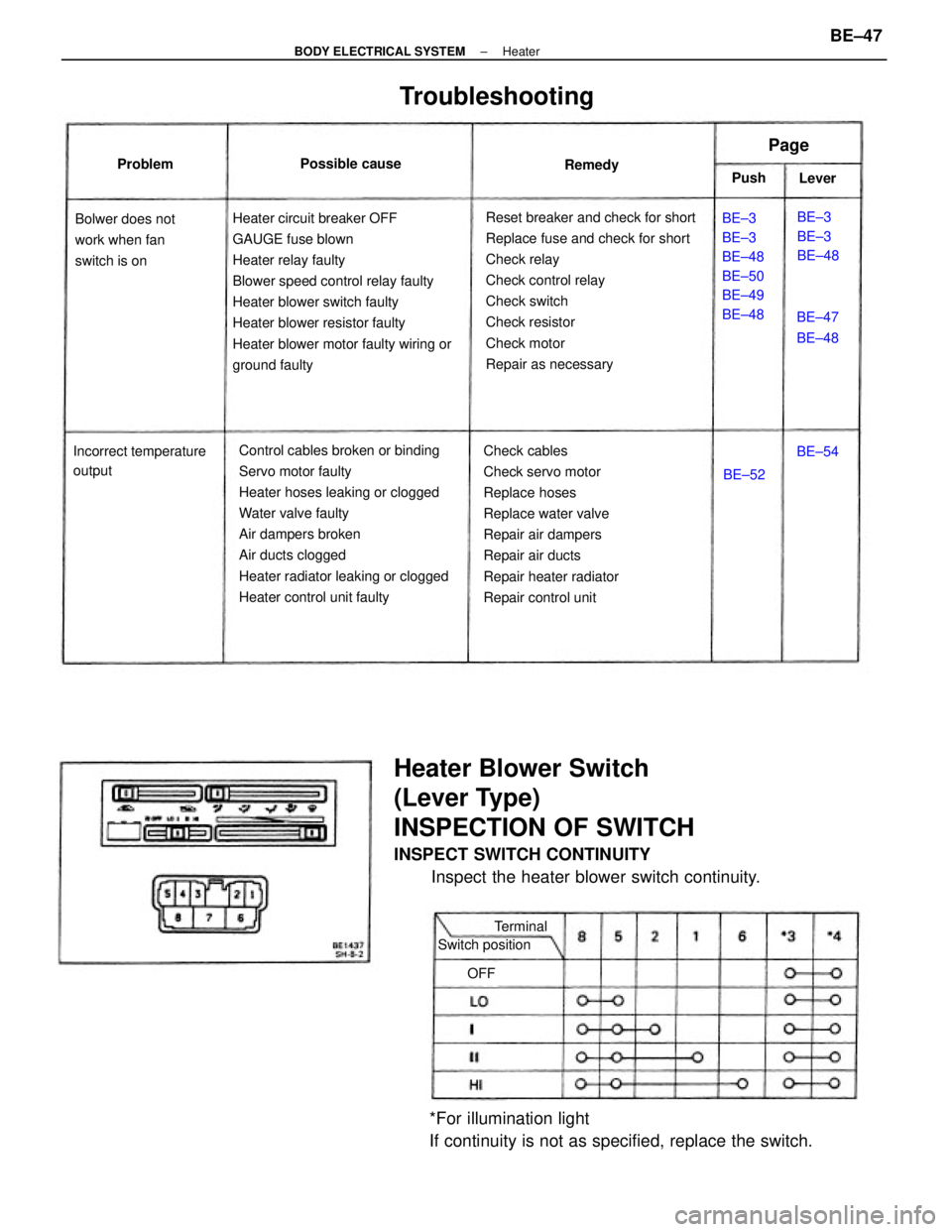
Heater Blower Switch
(Lever Type)
INSPECTION OF SWITCH
INSPECT SWITCH CONTINUITY
Inspect the heater blower switch continuity.
Control cables broken or binding
Servo motor faulty
Heater hoses leaking or clogged
Water valve faulty
Air dampers broken
Air ducts clogged
Heater radiator leaking or clogged
Heater control unit faulty Heater circuit breaker OFF
GAUGE fuse blown
Heater relay faulty
Blower speed control relay faulty
Heater blower switch faulty
Heater blower resistor faulty
Heater blower motor faulty wiring or
ground faultyReset breaker and check for short
Replace fuse and check for short
Check relay
Check control relay
Check switch
Check resistor
Check motor
Repair as necessary
Check cables
Check servo motor
Replace hoses
Replace water valve
Repair air dampers
Repair air ducts
Repair heater radiator
Repair control unit
*For illumination light
If continuity is not as specified, replace the switch.
Troubleshooting
BE±3
BE±3
BE±48
BE±50
BE±49
BE±48 Bolwer does not
work when fan
switch is on
Incorrect temperature
outputBE±3
BE±3
BE±48
Switch position Possible cause
BE±47
BE±48
Terminal Problem
Remedy
Lever
BE±52
Page
BE±54 Push
OFF
± BODY ELECTRICAL SYSTEMHeaterBE±47
Page 794 of 2389
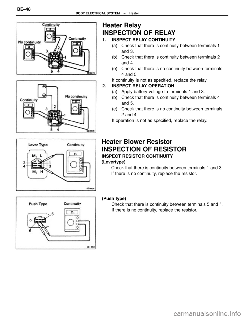
Heater Relay
INSPECTION OF RELAY
1. INSPECT RELAY CONTINUITY
(a) Check that there is continuity between terminals 1
and 3.
(b) Check that there is continuity between terminals 2
and 4.
(e) Check that there is no continuity between terminals
4 and 5.
If continuity is not as specified, replace the relay.
2. INSPECT RELAY OPERATION
(a) Apply battery voltage to terminals 1 and 3.
(b) Check that there is continuity between terminals 4
and 5.
(e) Check that there is no continuity between terminals
2 and 4.
If operation is not as specified, replace the relay.
Heater Blower Resistor
INSPECTION OF RESISTOR
INSPECT RESISTOR CONTINUITY
(Levertype)
Check that there is continuity between terminals 1 and 3.
If there is no continuity, replace the resistor.
(Push type)
Check that there is continuity between terminals 5 and ^.
If there is no continuity, replace the resistor.
± BODY ELECTRICAL SYSTEMHeaterBE±48
Page 796 of 2389
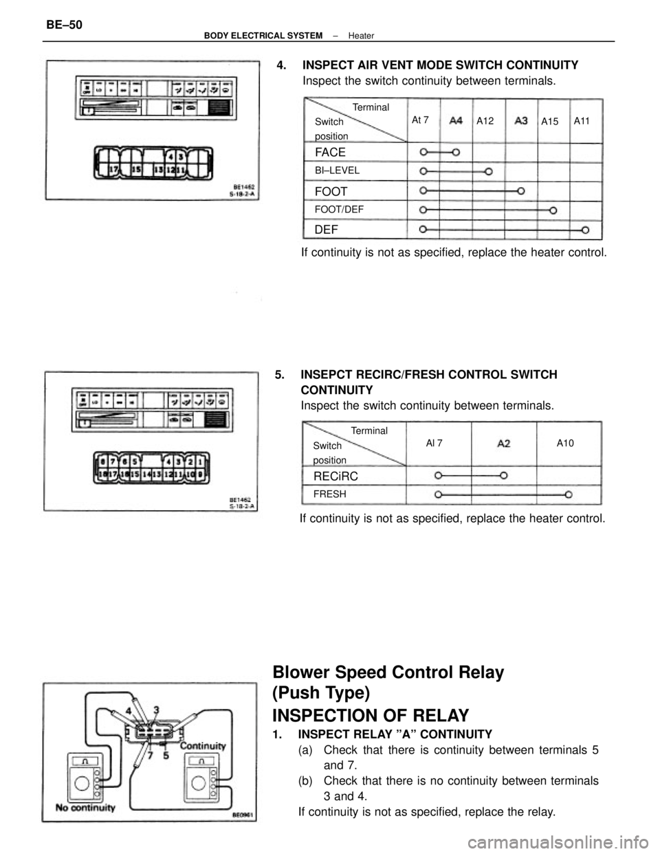
Blower Speed Control Relay
(Push Type)
INSPECTION OF RELAY
1. INSPECT RELAY ºAº CONTINUITY
(a) Check that there is continuity between terminals 5
and 7.
(b) Check that there is no continuity between terminals
3 and 4.
If continuity is not as specified, replace the relay. 5. INSEPCT RECIRC/FRESH CONTROL SWITCH
CONTINUITY
Inspect the switch continuity between terminals. 4. INSPECT AIR VENT MODE SWITCH CONTINUITY
Inspect the switch continuity between terminals.
If continuity is not as specified, replace the heater control.
If continuity is not as specified, replace the heater control.
Switch
positionSwitch
position
FOOT/DEFBI±LEVELTerminal
Terminal
RECiRC
FRESH
FA C E
FOOT
Al 7 A10 At 7
A11
DEF
A12
A15
± BODY ELECTRICAL SYSTEMHeaterBE±50