clock TOYOTA CAMRY V20 1986 Service Information
[x] Cancel search | Manufacturer: TOYOTA, Model Year: 1986, Model line: CAMRY V20, Model: TOYOTA CAMRY V20 1986Pages: 2389, PDF Size: 84.44 MB
Page 193 of 2389

AT4419
SST
AT4493
SST
AT4494
AT4495AT4524
4. ADJUST TOTAL PRELOAD
(a) Install the transfer right case.
(b) Install and torque the ten bolts.
Torque: 450 kg-cm (33 ft-lb, 44 N-m)
HINT: Do not apply seal packing and do not install gasket.
Each bolt length (mm, in.) is indicated in the figure.
(c) Using SST and a spring tension gauge, measure
the total preload.
SST 09326-2001 1
Preload (at starting):
Add driven pinion preload
0.5 - 0.9 kg (1.1 - 2.0 lb, 4.9 - 8.8 N)
HINT: Turn the drive pinion counterclockwise and clock-
wise several times.
(d) Adjust the total preload by tightening the adjusting
nut with SST.
SST 09318-12010
HINT: Measure the preload while tightening the bearing
adjusting nut a little at a time.
5. CHECK RING GEAR BACKLASH
(a) Using a dial indicator, measure the ring gear back-
lash.
Backlash: 0.13 - 0.18 mm (0.0051 - 0.0071 in.)
(b) When the backlash is outside the standard value,
select a different plate washer to the one selected in
step 3. Again adjust the backlash and total preload.
6. CHECK TOOTH CONTACT
(a) Coat 3 or 4 teeth at four different positions on the
ring gear with red lead.
(b) Rotate the ring gear, inspect the teeth pattern.
- TRANSFER (A540H)Assembly of Component PartsTF-33
Page 350 of 2389
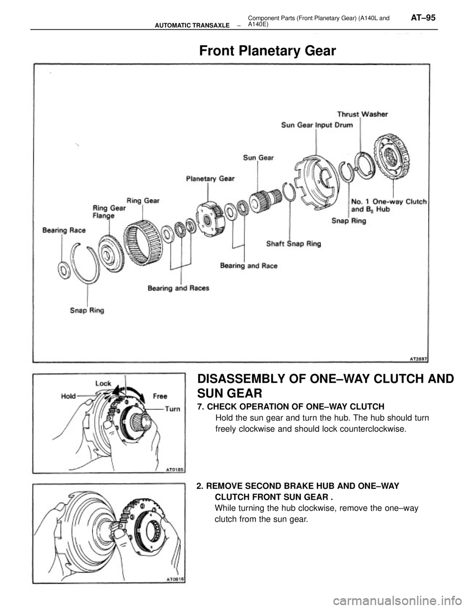
DISASSEMBLY OF ONE±WAY CLUTCH AND
SUN GEAR
7. CHECK OPERATION OF ONE±WAY CLUTCH
Hold the sun gear and turn the hub. The hub should turn
freely clockwise and should lock counterclockwise.
2. REMOVE SECOND BRAKE HUB AND ONE±WAY
CLUTCH FRONT SUN GEAR .
While turning the hub clockwise, remove the one±way
clutch from the sun gear.
Front Planetary Gear
± AUTOMATIC TRANSAXLEComponent Parts (Front Planetary Gear) (A140L and
A140E)AT±95
Page 352 of 2389
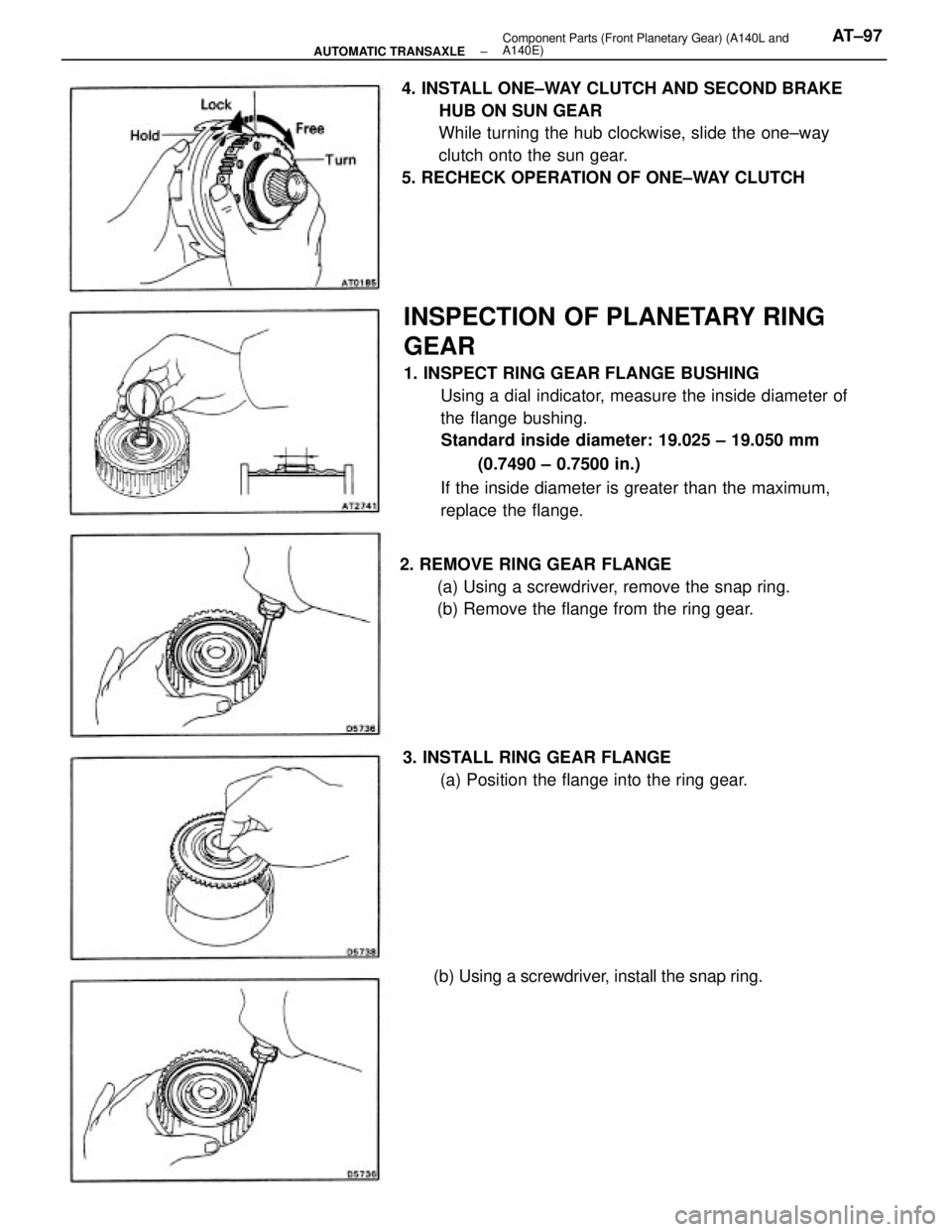
INSPECTION OF PLANETARY RING
GEAR
1. INSPECT RING GEAR FLANGE BUSHING
Using a dial indicator, measure the inside diameter of
the flange bushing.
Standard inside diameter: 19.025 ± 19.050 mm
(0.7490 ± 0.7500 in.)
If the inside diameter is greater than the maximum,
replace the flange. 4. INSTALL ONE±WAY CLUTCH AND SECOND BRAKE
HUB ON SUN GEAR
While turning the hub clockwise, slide the one±way
clutch onto the sun gear.
5. RECHECK OPERATION OF ONE±WAY CLUTCH
2. REMOVE RING GEAR FLANGE
(a) Using a screwdriver, remove the snap ring.
(b) Remove the flange from the ring gear.
3. INSTALL RING GEAR FLANGE
(a) Position the flange into the ring gear.
(b) Using a screwdriver, install the snap ring.
± AUTOMATIC TRANSAXLEComponent Parts (Front Planetary Gear) (A140L and
A140E)AT±97
Page 356 of 2389
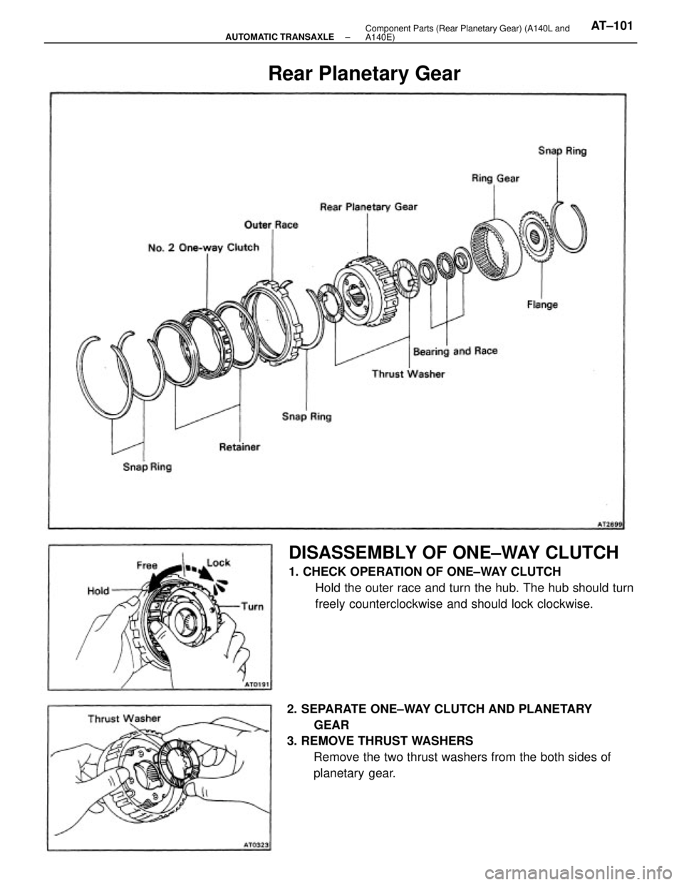
2. SEPARATE ONE±WAY CLUTCH AND PLANETARY
GEAR
3. REMOVE THRUST WASHERS
Remove the two thrust washers from the both sides of
planetary gear.
DISASSEMBLY OF ONE±WAY CLUTCH
1. CHECK OPERATION OF ONE±WAY CLUTCH
Hold the outer race and turn the hub. The hub should turn
freely counterclockwise and should lock clockwise.
Rear Planetary Gear
± AUTOMATIC TRANSAXLEComponent Parts (Rear Planetary Gear) (A140L and
A140E)AT±101
Page 366 of 2389
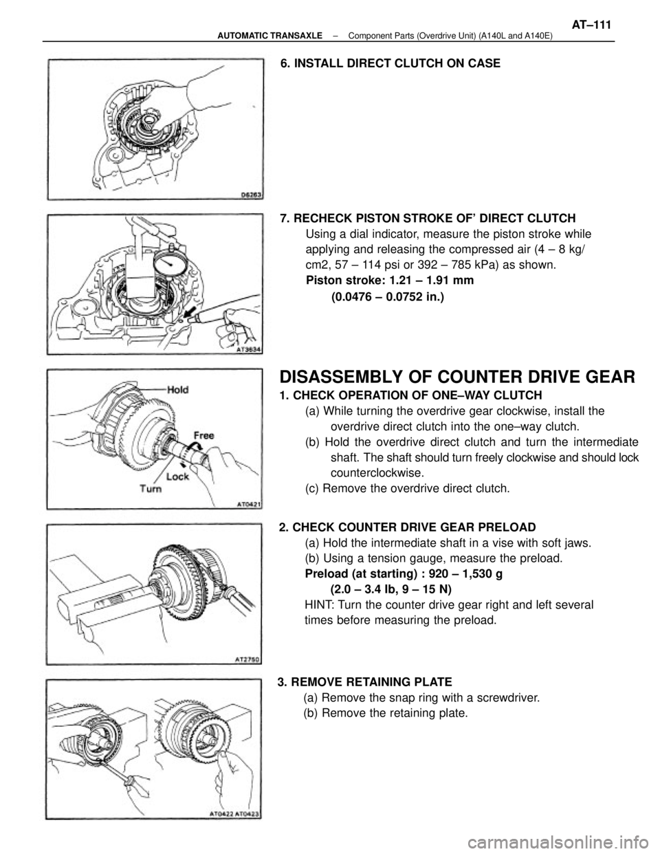
DISASSEMBLY OF COUNTER DRIVE GEAR
1. CHECK OPERATION OF ONE±WAY CLUTCH
(a) While turning the overdrive gear clockwise, install the
overdrive direct clutch into the one±way clutch.
(b) Hold the overdrive direct clutch and turn the intermediate
shaft. The shaft should turn freely clockwise and should lock
counterclockwise.
(c) Remove the overdrive direct clutch.
2. CHECK COUNTER DRIVE GEAR PRELOAD
(a) Hold the intermediate shaft in a vise with soft jaws.
(b) Using a tension gauge, measure the preload.
Preload (at starting) : 920 ± 1,530 g
(2.0 ± 3.4 Ib, 9 ± 15 N)
HINT: Turn the counter drive gear right and left several
times before measuring the preload. 7. RECHECK PISTON STROKE OF' DIRECT CLUTCH
Using a dial indicator, measure the piston stroke while
applying and releasing the compressed air (4 ± 8 kg/
cm2, 57 ± 114 psi or 392 ± 785 kPa) as shown.
Piston stroke: 1.21 ± 1.91 mm
(0.0476 ± 0.0752 in.)
3. REMOVE RETAINING PLATE
(a) Remove the snap ring with a screwdriver.
(b) Remove the retaining plate. 6. INSTALL DIRECT CLUTCH ON CASE
± AUTOMATIC TRANSAXLEComponent Parts (Overdrive Unit) (A140L and A140E)AT±111
Page 372 of 2389
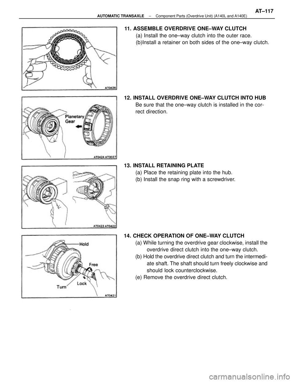
14. CHECK OPERATION OF ONE±WAY CLUTCH
(a) While turning the overdrive gear clockwise, install the
overdrive direct clutch into the one±way clutch.
(b) Hold the overdrive direct clutch and turn the intermedi-
ate shaft. The shaft should turn freely clockwise and
should lock counterclockwise.
(e) Remove the overdrive direct clutch. 11. ASSEMBLE OVERDRIVE ONE±WAY CLUTCH
(a) Install the one±way clutch into the outer race.
(b)Install a retainer on both sides of the one±way clutch.
12. INSTALL OVERDRIVE ONE±WAY CLUTCH INTO HUB
Be sure that the one±way clutch is installed in the cor-
rect direction.
13. INSTALL RETAINING PLATE
(a) Place the retaining plate into the hub.
(b) Install the snap ring with a screwdriver.
± AUTOMATIC TRANSAXLEComponent Parts (Overdrive Unit) (A140L and A140E)AT±117
Page 375 of 2389
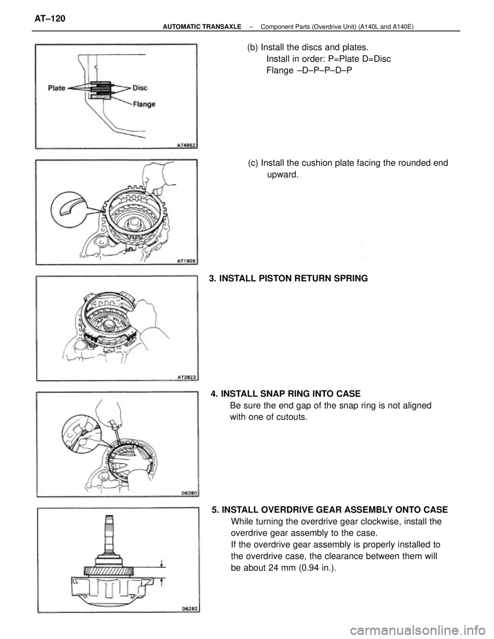
5. INSTALL OVERDRIVE GEAR ASSEMBLY ONTO CASE
While turning the overdrive gear clockwise, install the
overdrive gear assembly to the case.
If the overdrive gear assembly is properly installed to
the overdrive case, the clearance between them will
be about 24 mm (0.94 in.). 4. INSTALL SNAP RING INTO CASE
Be sure the end gap of the snap ring is not aligned
with one of cutouts.(b) Install the discs and plates.
Install in order: P=Plate D=Disc
Flange ±D±P±P±D±P
(c) Install the cushion plate facing the rounded end
upward.
3. INSTALL PISTON RETURN SPRING
± AUTOMATIC TRANSAXLEComponent Parts (Overdrive Unit) (A140L and A140E)AT±120
Page 411 of 2389
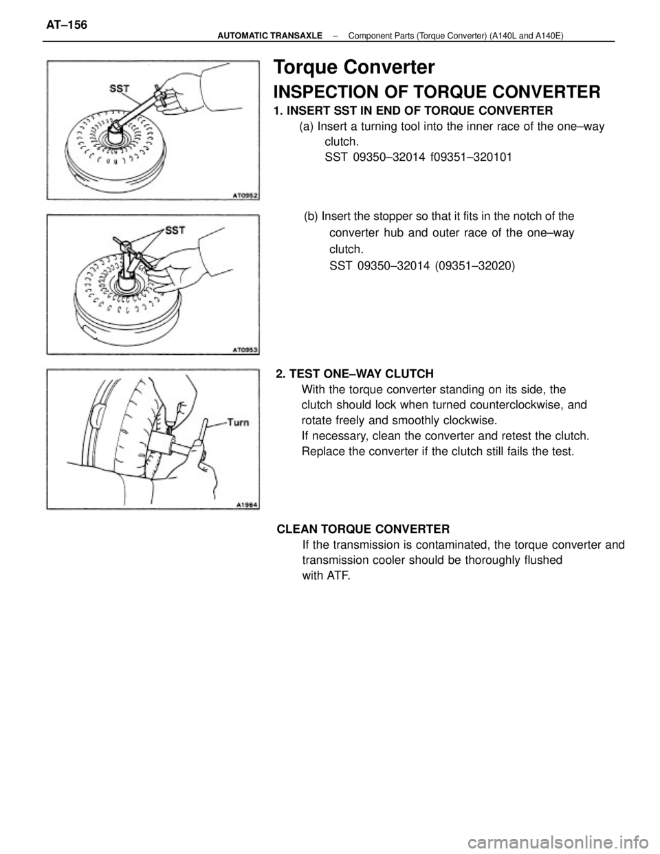
Torque Converter
INSPECTION OF TORQUE CONVERTER
1. INSERT SST IN END OF TORQUE CONVERTER
(a) Insert a turning tool into the inner race of the one±way
clutch.
SST 09350±32014 f09351±320101
2. TEST ONE±WAY CLUTCH
With the torque converter standing on its side, the
clutch should lock when turned counterclockwise, and
rotate freely and smoothly clockwise.
If necessary, clean the converter and retest the clutch.
Replace the converter if the clutch still fails the test.
CLEAN TORQUE CONVERTER
If the transmission is contaminated, the torque converter and
transmission cooler should be thoroughly flushed
with ATF.(b) Insert the stopper so that it fits in the notch of the
converter hub and outer race of the one±way
clutch.
SST 09350±32014 (09351±32020)
± AUTOMATIC TRANSAXLEComponent Parts (Torque Converter) (A140L and A140E)AT±156
Page 416 of 2389
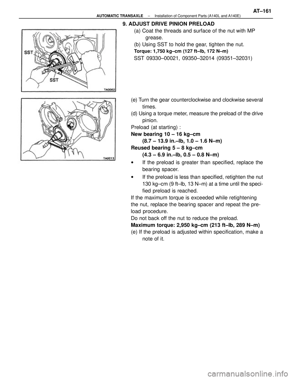
(e) Turn the gear counterclockwise and clockwise several
times.
(d) Using a torque meter, measure the preload of the drive
pinion.
Preload (at starting) :
New bearing 10 ± 16 kg±cm
(8.7 ± 13.9 in.±lb, 1.0 ± 1.6 N±m)
Reused bearing 5 ± 8 kg±cm
(4.3 ± 6.9 in.±Ib, 0.5 ± 0.8 N±m)
wIf the preload is greater than specified, replace the
bearing spacer.
wIf the preload is less than specified, retighten the nut
130 kg±cm (9 ft±lb, 13 N±m) at a time until the speci-
fied preload is reached.
If the maximum torque is exceeded while retightening
the nut, replace the bearing spacer and repeat the pre-
load procedure.
Do not back off the nut to reduce the preload.
Maximum torque: 2,950 kg±cm (213 ft±Ib, 289 N±m)
(e) If the preload is adjusted within specification, make a
note of it. 9. ADJUST DRIVE PINION PRELOAD
(a) Coat the threads and surface of the nut with MP
grease.
(b) Using SST to hold the gear, tighten the nut.
Torque: 1,750 kg±cm (127 ft±lb, 172 N±m)
SST 09330±00021, 09350±32014 (09351±32031)
± AUTOMATIC TRANSAXLEInstallation of Component Parts (A140L and A140E)AT±161
Page 424 of 2389
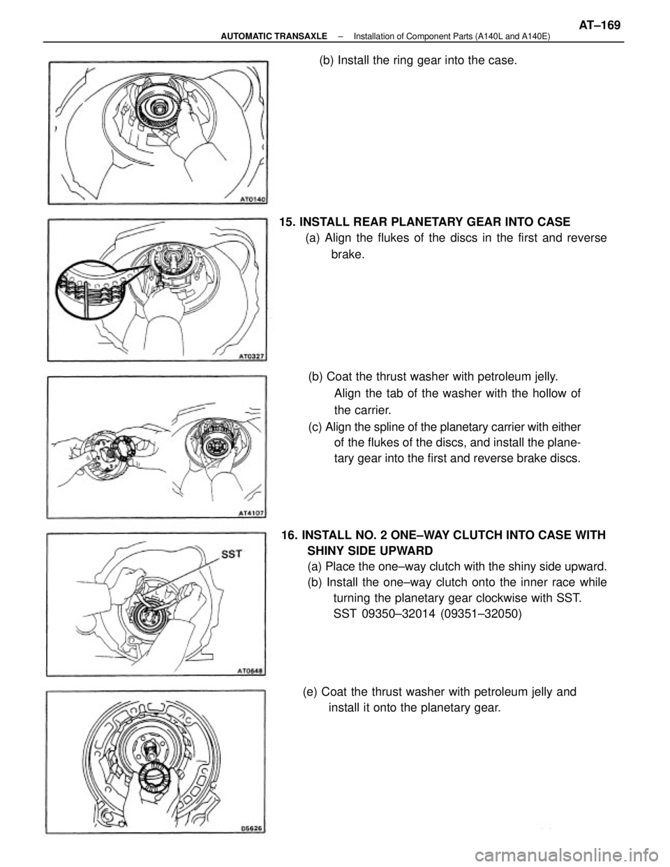
16. INSTALL NO. 2 ONE±WAY CLUTCH INTO CASE WITH
SHINY SIDE UPWARD
(a) Place the one±way clutch with the shiny side upward.
(b) Install the one±way clutch onto the inner race while
turning the planetary gear clockwise with SST.
SST 09350±32014 (09351±32050) (b) Coat the thrust washer with petroleum jelly.
Align the tab of the washer with the hollow of
the carrier.
(c) Align the spline of the planetary carrier with either
of the flukes of the discs, and install the plane-
tary gear into the first and reverse brake discs. 15. INSTALL REAR PLANETARY GEAR INTO CASE
(a) Align the flukes of the discs in the first and reverse
brake.
(e) Coat the thrust washer with petroleum jelly and
install it onto the planetary gear. (b) Install the ring gear into the case.
± AUTOMATIC TRANSAXLEInstallation of Component Parts (A140L and A140E)AT±169