clock TOYOTA CAMRY V20 1986 Service Information
[x] Cancel search | Manufacturer: TOYOTA, Model Year: 1986, Model line: CAMRY V20, Model: TOYOTA CAMRY V20 1986Pages: 2389, PDF Size: 84.44 MB
Page 425 of 2389
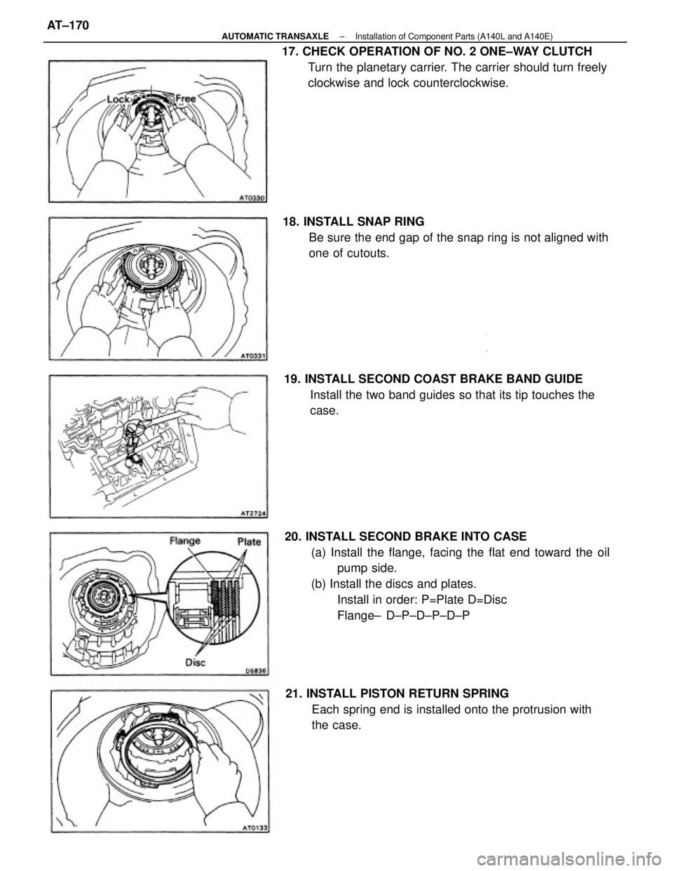
20. INSTALL SECOND BRAKE INTO CASE
(a) Install the flange, facing the flat end toward the oil
pump side.
(b) Install the discs and plates.
Install in order: P=Plate D=Disc
Flange± D±P±D±P±D±P 17. CHECK OPERATION OF NO. 2 ONE±WAY CLUTCH
Turn the planetary carrier. The carrier should turn freely
clockwise and lock counterclockwise.
18. INSTALL SNAP RING
Be sure the end gap of the snap ring is not aligned with
one of cutouts.
21. INSTALL PISTON RETURN SPRING
Each spring end is installed onto the protrusion with
the case. 19. INSTALL SECOND COAST BRAKE BAND GUIDE
Install the two band guides so that its tip touches the
case.
± AUTOMATIC TRANSAXLEInstallation of Component Parts (A140L and A140E)AT±170
Page 427 of 2389
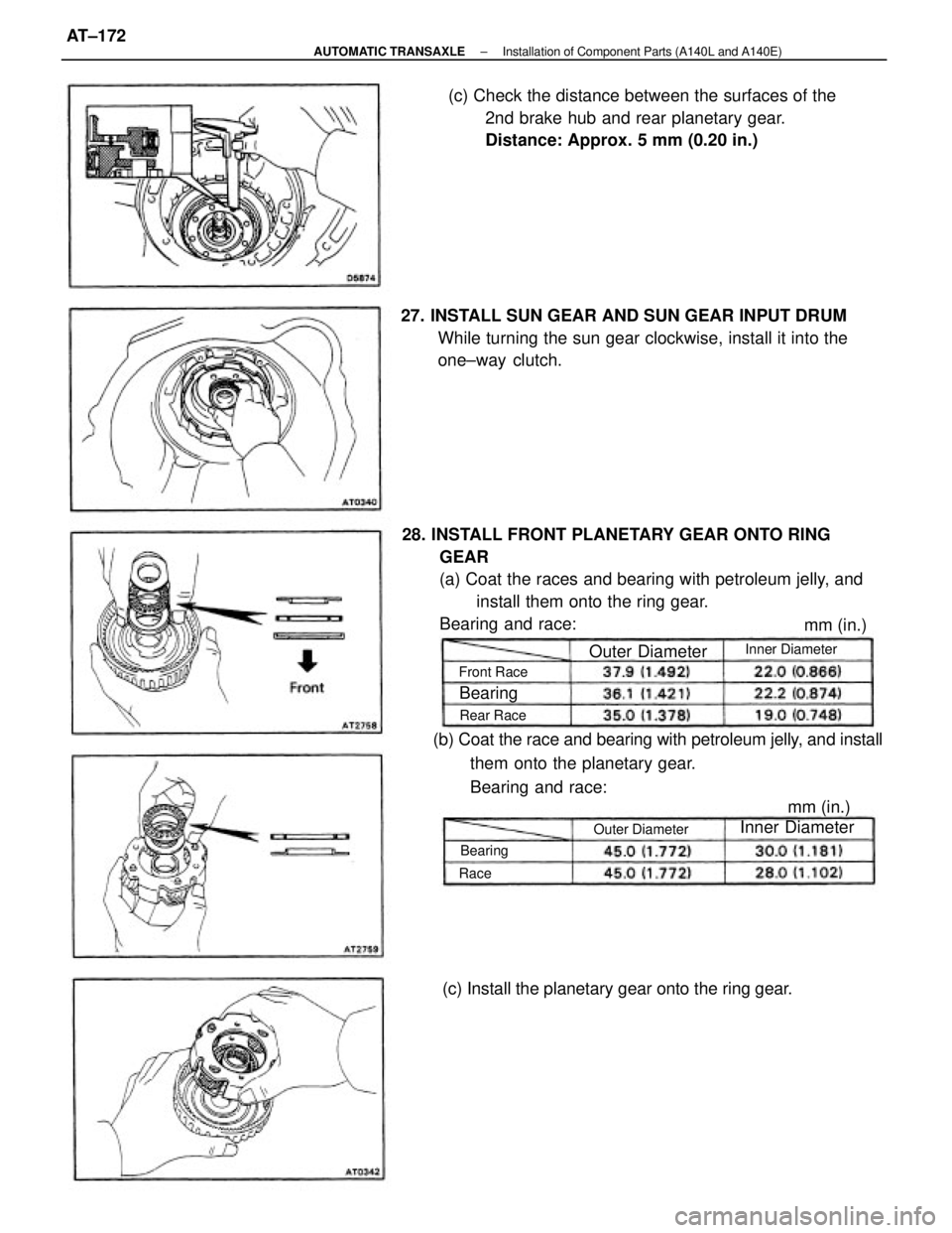
28. INSTALL FRONT PLANETARY GEAR ONTO RING
GEAR
(a) Coat the races and bearing with petroleum jelly, and
install them onto the ring gear.
Bearing and race:(c) Check the distance between the surfaces of the
2nd brake hub and rear planetary gear.
Distance: Approx. 5 mm (0.20 in.)
(b) Coat the race and bearing with petroleum jelly, and install
them onto the planetary gear.
Bearing and race: 27. INSTALL SUN GEAR AND SUN GEAR INPUT DRUM
While turning the sun gear clockwise, install it into the
one±way clutch.
(c) Install the planetary gear onto the ring gear.Outer Diameter
Outer DiameterInner DiameterInner Diameter
Front Race
mm (in.)
Rear Race
mm (in.)
Bearing
Bearing
Race
± AUTOMATIC TRANSAXLEInstallation of Component Parts (A140L and A140E)AT±172
Page 448 of 2389
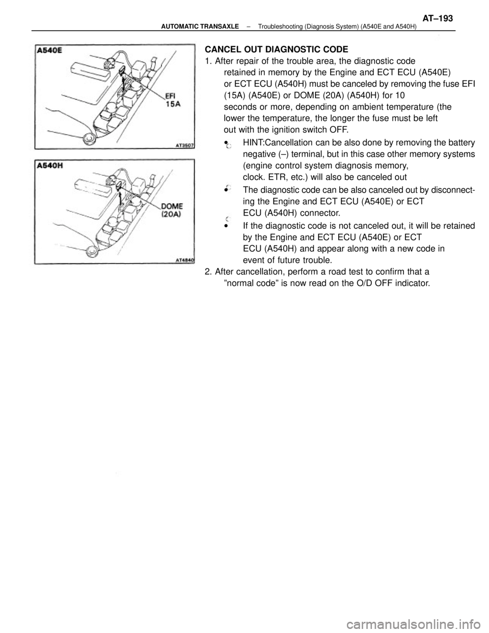
CANCEL OUT DIAGNOSTIC CODE
1. After repair of the trouble area, the diagnostic code
retained in memory by the Engine and ECT ECU (A540E)
or ECT ECU (A540H) must be canceled by removing the fuse EFI
(15A) (A540E) or DOME (20A) (A540H) for 10
seconds or more, depending on ambient temperature (the
lower the temperature, the longer the fuse must be left
out with the ignition switch OFF.
wHINT:Cancellation can be also done by removing the battery
negative (±) terminal, but in this case other memory systems
(engine control system diagnosis memory,
clock. ETR, etc.) will also be canceled out
wThe diagnostic code can be also canceled out by disconnect-
ing the Engine and ECT ECU (A540E) or ECT
ECU (A540H) connector.
wIf the diagnostic code is not canceled out, it will be retained
by the Engine and ECT ECU (A540E) or ECT
ECU (A540H) and appear along with a new code in
event of future trouble.
2. After cancellation, perform a road test to confirm that a
ºnormal codeº is now read on the O/D OFF indicator.
± AUTOMATIC TRANSAXLETroubleshooting (Diagnosis System) (A540E and A540H)AT±193
Page 535 of 2389
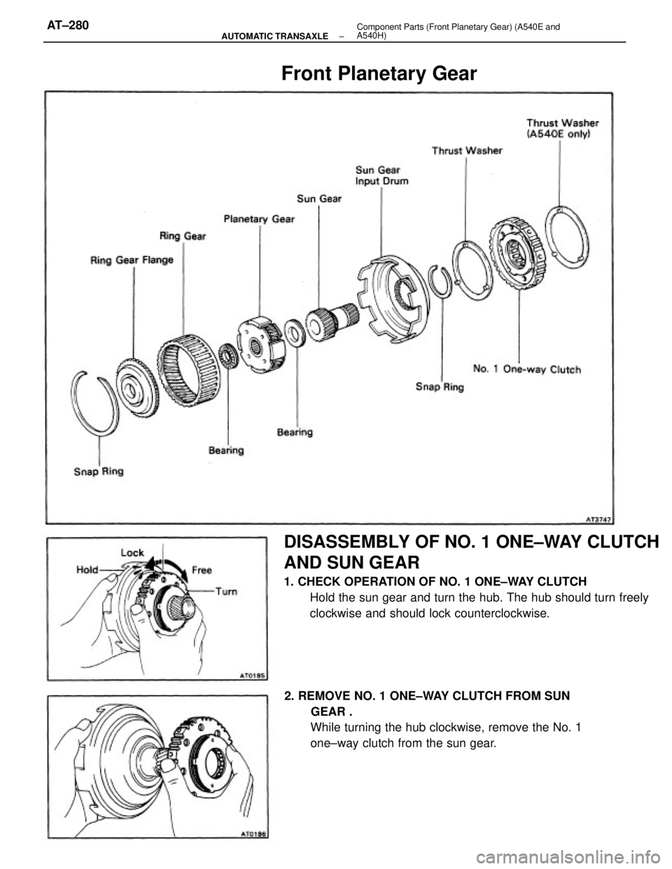
DISASSEMBLY OF NO. 1 ONE±WAY CLUTCH
AND SUN GEAR
1. CHECK OPERATION OF NO. 1 ONE±WAY CLUTCH
Hold the sun gear and turn the hub. The hub should turn freely
clockwise and should lock counterclockwise.
2. REMOVE NO. 1 ONE±WAY CLUTCH FROM SUN
GEAR .
While turning the hub clockwise, remove the No. 1
one±way clutch from the sun gear.
Front Planetary Gear
± AUTOMATIC TRANSAXLEComponent Parts (Front Planetary Gear) (A540E and
A540H)AT±280
Page 537 of 2389

INSPECTION OF PLANETARY RING GEAR
1. INSPECT RING GEAR FLANGE BUSHING
Using a dial indicator, measure the inside diameter of the
flange bushing.
Maximum inside diameter: 30.08 mm (1.1842 in.)
If the inside diameter is greater than the maximum, replace
the flange. 3. INSTALL NO. 1 ONE±WAY CLUTCH ON SUN GEAR
While turning the hub clockwise, slide the No. 1 one±
way clutch onto the sun gear.
4. RECHECK OPERATION OF NO. 1 ONE±WAY CLUTCH
2. REMOVE RING GEAR FLANGE
(a) Using a screwdriver, remove the snap ring.
(b) Remove the flange from the ring gear.
3. INSTALL RING GEAR FLANGE
(a) Position the flange into the ring gear.
(b) Using a screwdriver, install the snap ring.
± AUTOMATIC TRANSAXLEComponent Parts (Front Planetary Gear) (A540E and
A540H)AT±282
Page 541 of 2389
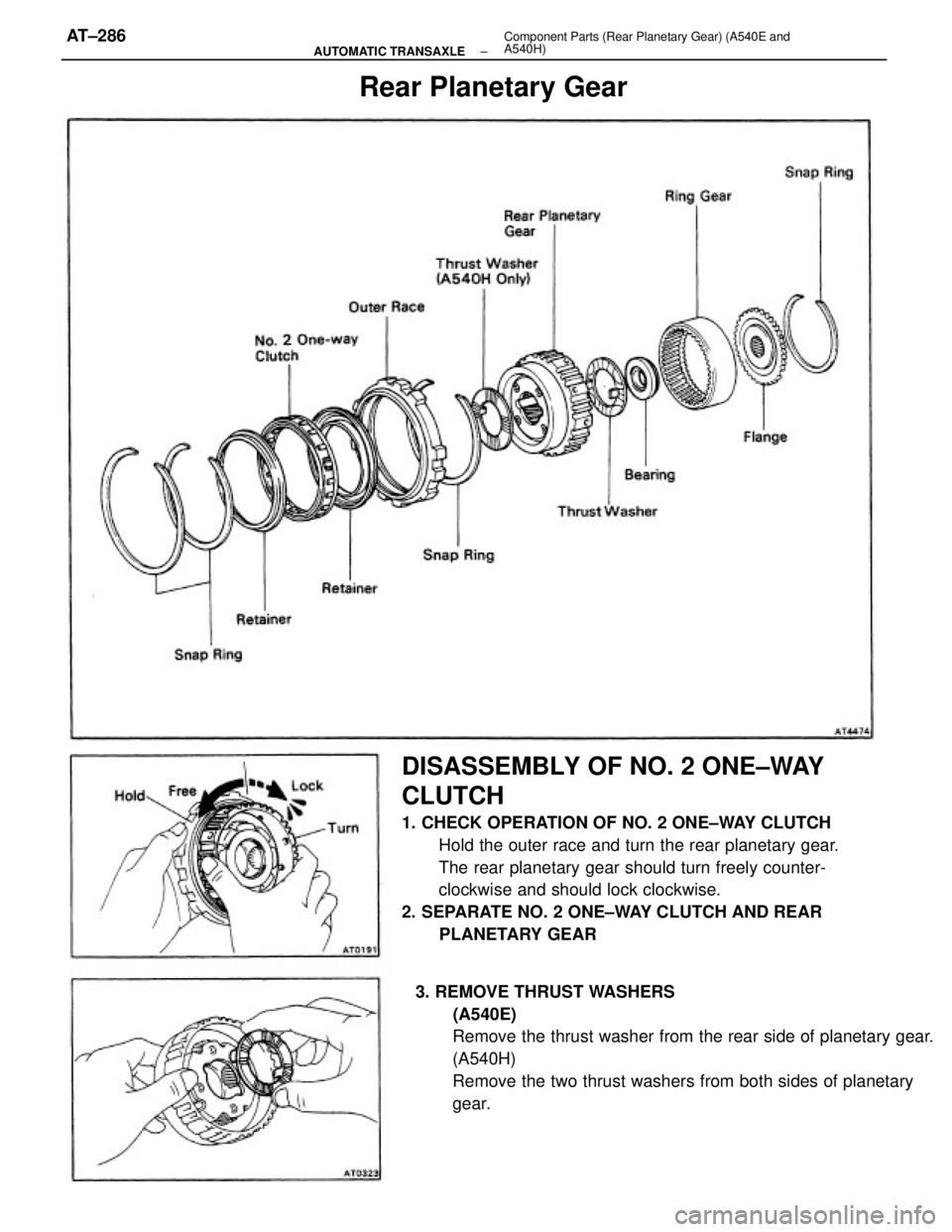
DISASSEMBLY OF NO. 2 ONE±WAY
CLUTCH
1. CHECK OPERATION OF NO. 2 ONE±WAY CLUTCH
Hold the outer race and turn the rear planetary gear.
The rear planetary gear should turn freely counter-
clockwise and should lock clockwise.
2. SEPARATE NO. 2 ONE±WAY CLUTCH AND REAR
PLANETARY GEAR
3. REMOVE THRUST WASHERS
(A540E)
Remove the thrust washer from the rear side of planetary gear.
(A540H)
Remove the two thrust washers from both sides of planetary
gear.
Rear Planetary Gear
± AUTOMATIC TRANSAXLEComponent Parts (Rear Planetary Gear) (A540E and
A540H)AT±286
Page 551 of 2389
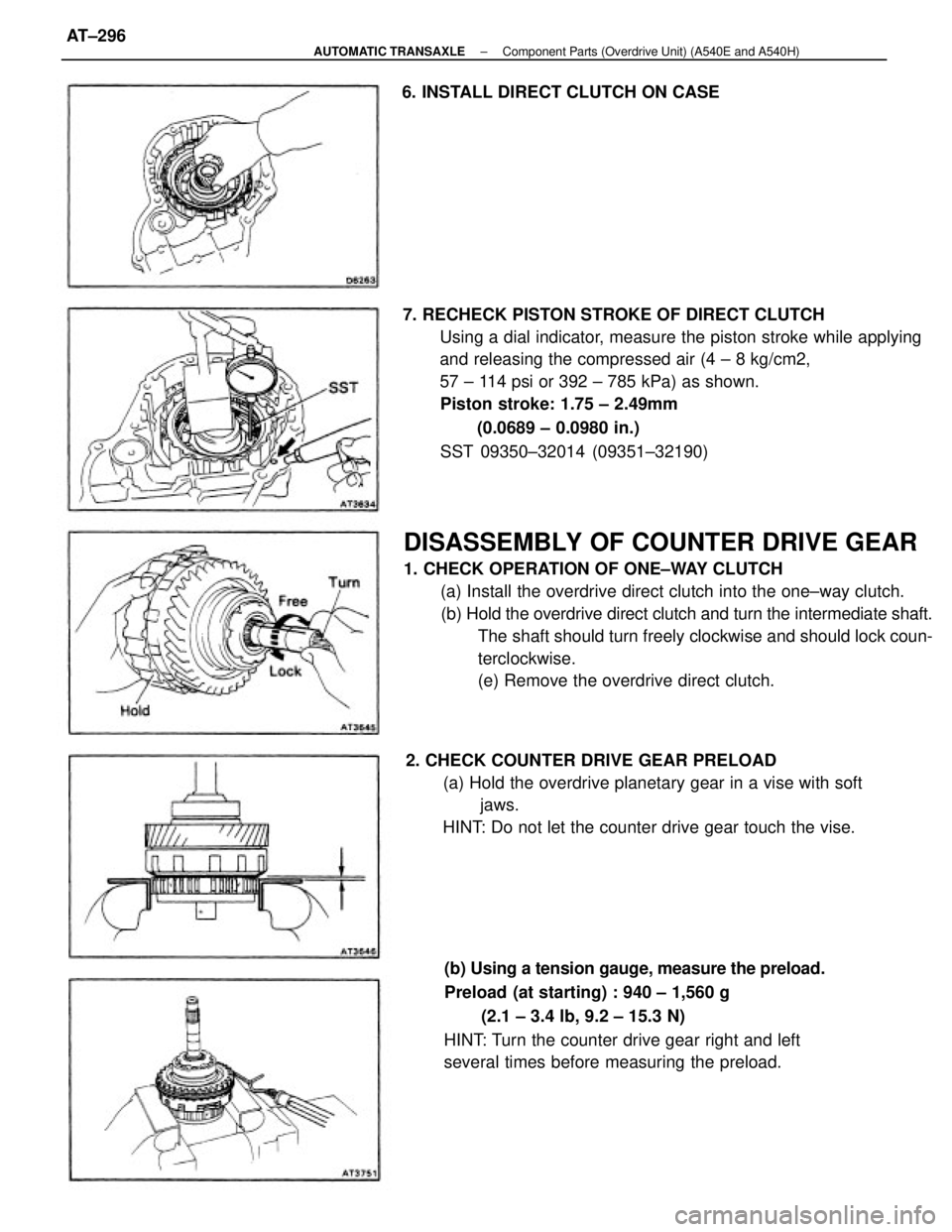
DISASSEMBLY OF COUNTER DRIVE GEAR
1. CHECK OPERATION OF ONE±WAY CLUTCH
(a) Install the overdrive direct clutch into the one±way clutch.
(b) Hold the overdrive direct clutch and turn the intermediate shaft.
The shaft should turn freely clockwise and should lock coun-
terclockwise.
(e) Remove the overdrive direct clutch. 7. RECHECK PISTON STROKE OF DIRECT CLUTCH
Using a dial indicator, measure the piston stroke while applying
and releasing the compressed air (4 ± 8 kg/cm2,
57 ± 114 psi or 392 ± 785 kPa) as shown.
Piston stroke: 1.75 ± 2.49mm
(0.0689 ± 0.0980 in.)
SST 09350±32014 (09351±32190)
(b) Using a tension gauge, measure the preload.
Preload (at starting) : 940 ± 1,560 g
(2.1 ± 3.4 lb, 9.2 ± 15.3 N)
HINT: Turn the counter drive gear right and left
several times before measuring the preload. 2. CHECK COUNTER DRIVE GEAR PRELOAD
(a) Hold the overdrive planetary gear in a vise with soft
jaws.
HINT: Do not let the counter drive gear touch the vise. 6. INSTALL DIRECT CLUTCH ON CASE
± AUTOMATIC TRANSAXLEComponent Parts (Overdrive Unit) (A540E and A540H)AT±296
Page 558 of 2389
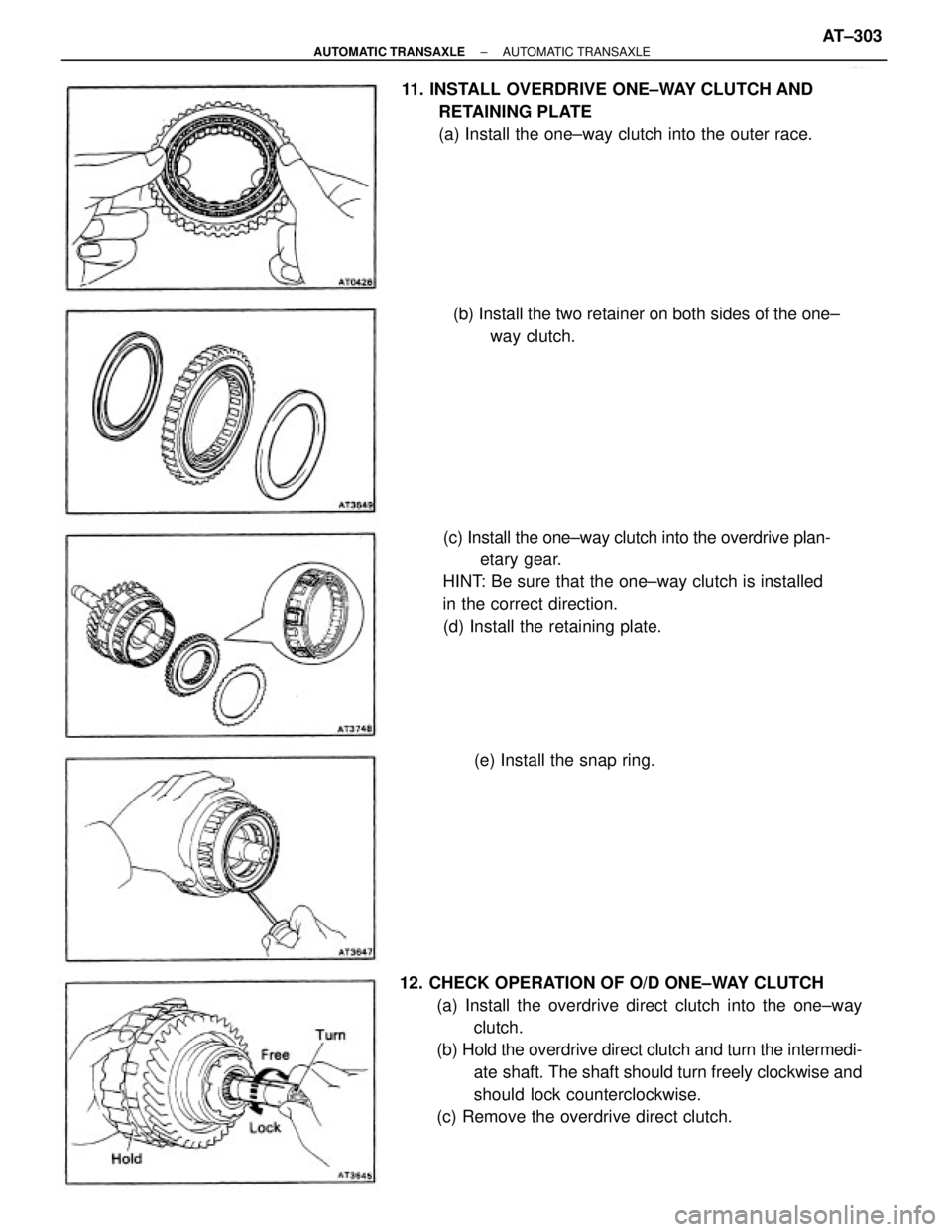
12. CHECK OPERATION OF O/D ONE±WAY CLUTCH
(a) Install the overdrive direct clutch into the one±way
clutch.
(b) Hold the overdrive direct clutch and turn the intermedi-
ate shaft. The shaft should turn freely clockwise and
should lock counterclockwise.
(c) Remove the overdrive direct clutch.(c) Install the one±way clutch into the overdrive plan-
etary gear.
HINT: Be sure that the one±way clutch is installed
in the correct direction.
(d) Install the retaining plate. 11. INSTALL OVERDRIVE ONE±WAY CLUTCH AND
RETAINING PLATE
(a) Install the one±way clutch into the outer race.
(b) Install the two retainer on both sides of the one±
way clutch.
(e) Install the snap ring.
± AUTOMATIC TRANSAXLEAUTOMATIC TRANSAXLEAT±303
Page 561 of 2389
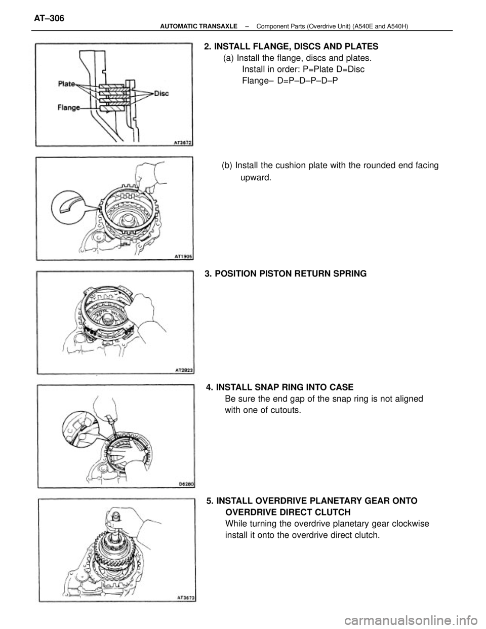
5. INSTALL OVERDRIVE PLANETARY GEAR ONTO
OVERDRIVE DIRECT CLUTCH
While turning the overdrive planetary gear clockwise
install it onto the overdrive direct clutch. 2. INSTALL FLANGE, DISCS AND PLATES
(a) Install the flange, discs and plates.
Install in order: P=Plate D=Disc
Flange± D=P±D±P±D±P
4. INSTALL SNAP RING INTO CASE
Be sure the end gap of the snap ring is not aligned
with one of cutouts. (b) Install the cushion plate with the rounded end facing
upward.
3. POSITION PISTON RETURN SPRING
± AUTOMATIC TRANSAXLEComponent Parts (Overdrive Unit) (A540E and A540H)AT±306
Page 621 of 2389
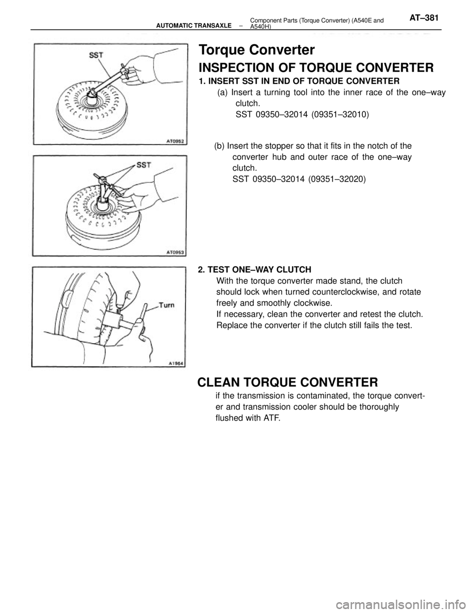
Torque Converter
INSPECTION OF TORQUE CONVERTER
1. INSERT SST IN END OF TORQUE CONVERTER
(a) Insert a turning tool into the inner race of the one±way
clutch.
SST 09350±32014 (09351±32010)
2. TEST ONE±WAY CLUTCH
With the torque converter made stand, the clutch
should lock when turned counterclockwise, and rotate
freely and smoothly clockwise.
If necessary, clean the converter and retest the clutch.
Replace the converter if the clutch still fails the test.
CLEAN TORQUE CONVERTER
if the transmission is contaminated, the torque convert-
er and transmission cooler should be thoroughly
flushed with ATF. (b) Insert the stopper so that it fits in the notch of the
converter hub and outer race of the one±way
clutch.
SST 09350±32014 (09351±32020)
± AUTOMATIC TRANSAXLEComponent Parts (Torque Converter) (A540E and
A540H)AT±381