clock TOYOTA CAMRY V20 1986 Service Information
[x] Cancel search | Manufacturer: TOYOTA, Model Year: 1986, Model line: CAMRY V20, Model: TOYOTA CAMRY V20 1986Pages: 2389, PDF Size: 84.44 MB
Page 1247 of 2389
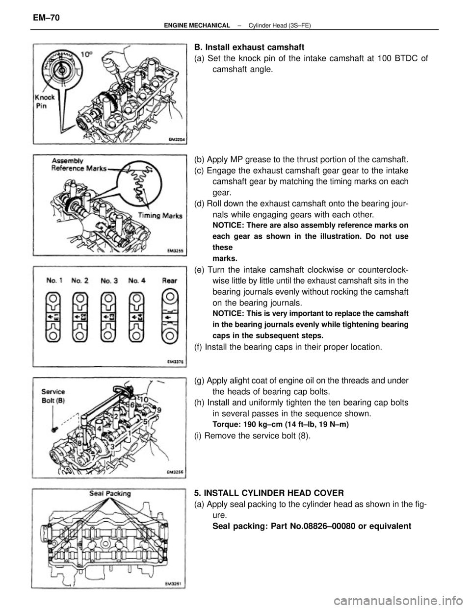
(b) Apply MP grease to the thrust portion of the camshaft.
(c) Engage the exhaust camshaft gear gear to the intake
camshaft gear by matching the timing marks on each
gear.
(d) Roll down the exhaust camshaft onto the bearing jour-
nals while engaging gears with each other.
NOTICE: There are also assembly reference marks on
each gear as shown in the illustration. Do not use
these
marks.
(e) Turn the intake camshaft clockwise or counterclock-
wise little by little until the exhaust camshaft sits in the
bearing journals evenly without rocking the camshaft
on the bearing journals.
NOTICE: This is very important to replace the camshaft
in the bearing journals evenly while tightening bearing
caps in the subsequent steps.
(f) Install the bearing caps in their proper location.
(g) Apply alight coat of engine oil on the threads and under
the heads of bearing cap bolts.
(h) Install and uniformly tighten the ten bearing cap bolts
in several passes in the sequence shown.
Torque: 190 kg±cm (14 ft±lb, 19 N±m)
(i) Remove the service bolt (8).
5. INSTALL CYLINDER HEAD COVER
(a) Apply seal packing to the cylinder head as shown in the fig-
ure.
Seal packing: Part No.08826±00080 or equivalent B. Install exhaust camshaft
(a) Set the knock pin of the intake camshaft at 100 BTDC of
camshaft angle.
± ENGINE MECHANICALCylinder Head (3S±FE)EM±70
Page 1259 of 2389
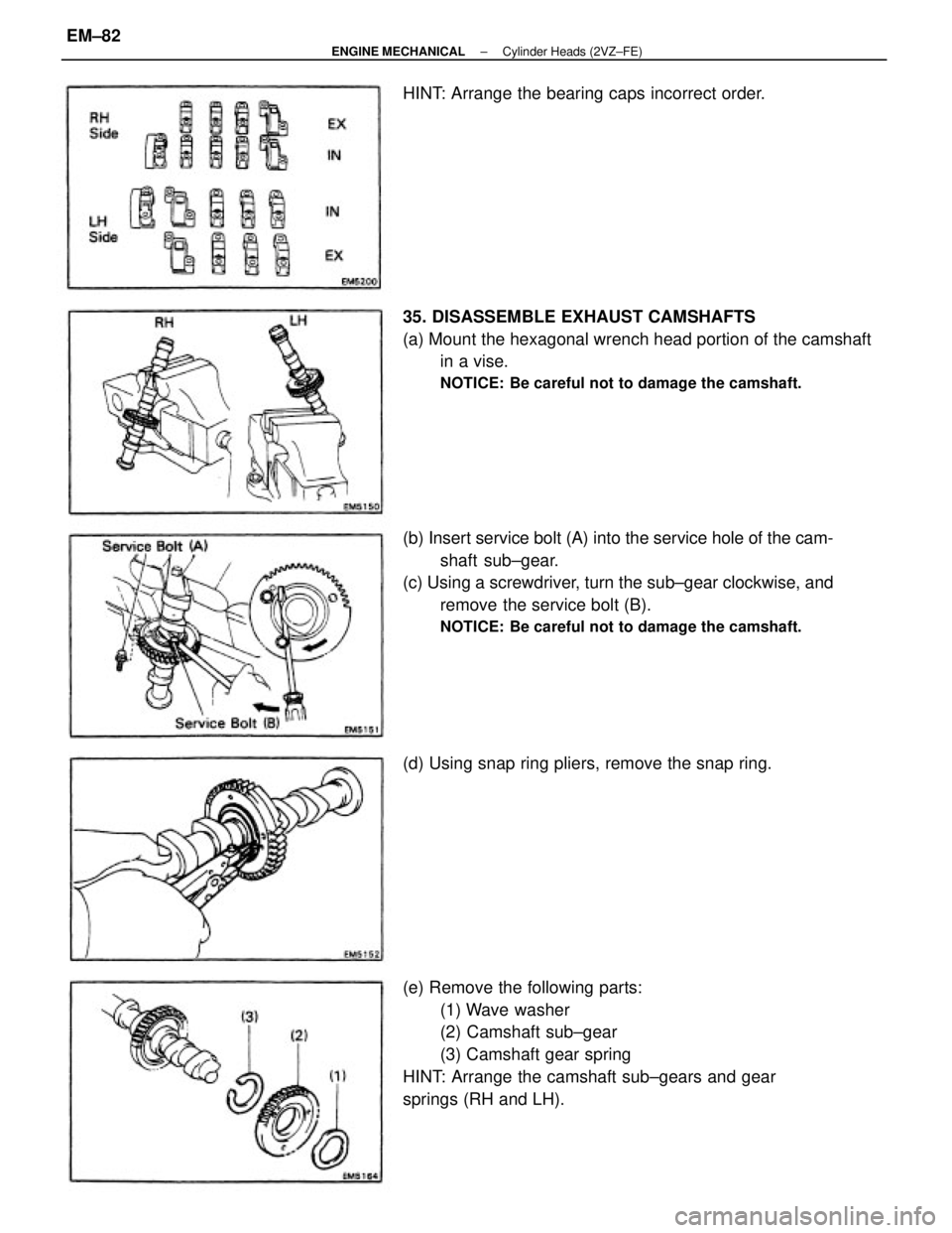
(e) Remove the following parts:
(1) Wave washer
(2) Camshaft sub±gear
(3) Camshaft gear spring
HINT: Arrange the camshaft sub±gears and gear
springs (RH and LH). (b) Insert service bolt (A) into the service hole of the cam-
shaft sub±gear.
(c) Using a screwdriver, turn the sub±gear clockwise, and
remove the service bolt (B).
NOTICE: Be careful not to damage the camshaft.
35. DISASSEMBLE EXHAUST CAMSHAFTS
(a) Mount the hexagonal wrench head portion of the camshaft
in a vise.
NOTICE: Be careful not to damage the camshaft.
(d) Using snap ring pliers, remove the snap ring. HINT: Arrange the bearing caps incorrect order.
± ENGINE MECHANICALCylinder Heads (2VZ±FE)EM±82
Page 1275 of 2389
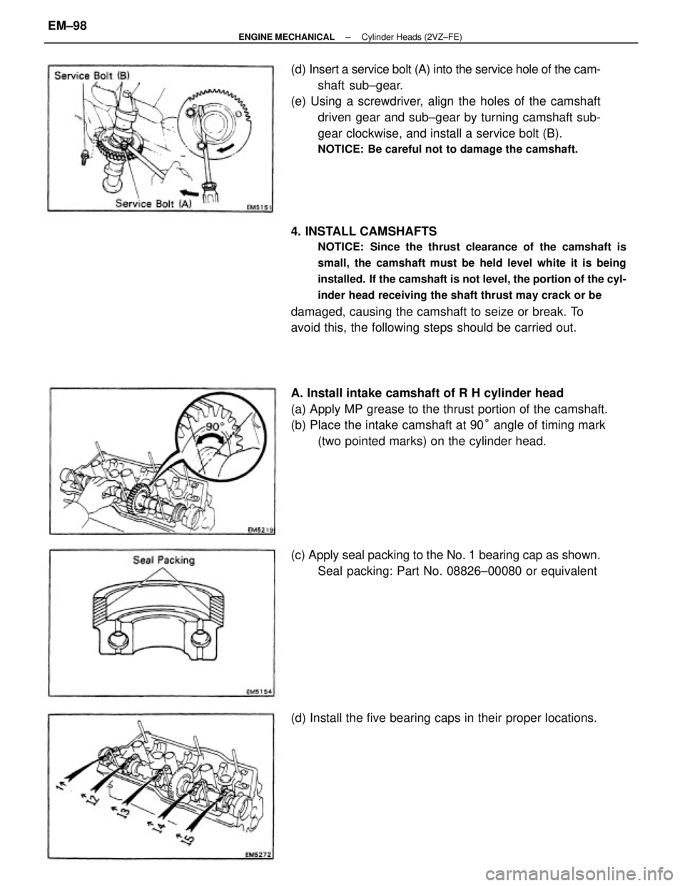
4. INSTALL CAMSHAFTS
NOTICE: Since the thrust clearance of the camshaft is
small, the camshaft must be held level white it is being
installed. If the camshaft is not level, the portion of the cyl-
inder head receiving the shaft thrust may crack or be
damaged, causing the camshaft to seize or break. To
avoid this, the following steps should be carried out. (d) Insert a service bolt (A) into the service hole of the cam-
shaft sub±gear.
(e) Using a screwdriver, align the holes of the camshaft
driven gear and sub±gear by turning camshaft sub-
gear clockwise, and install a service bolt (B).
NOTICE: Be careful not to damage the camshaft.
A. Install intake camshaft of R H cylinder head
(a) Apply MP grease to the thrust portion of the camshaft.
(b) Place the intake camshaft at 90° angle of timing mark
(two pointed marks) on the cylinder head.
(c) Apply seal packing to the No. 1 bearing cap as shown.
Seal packing: Part No. 08826±00080 or equivalent
(d) Install the five bearing caps in their proper locations.
± ENGINE MECHANICALCylinder Heads (2VZ±FE)EM±98
Page 1849 of 2389
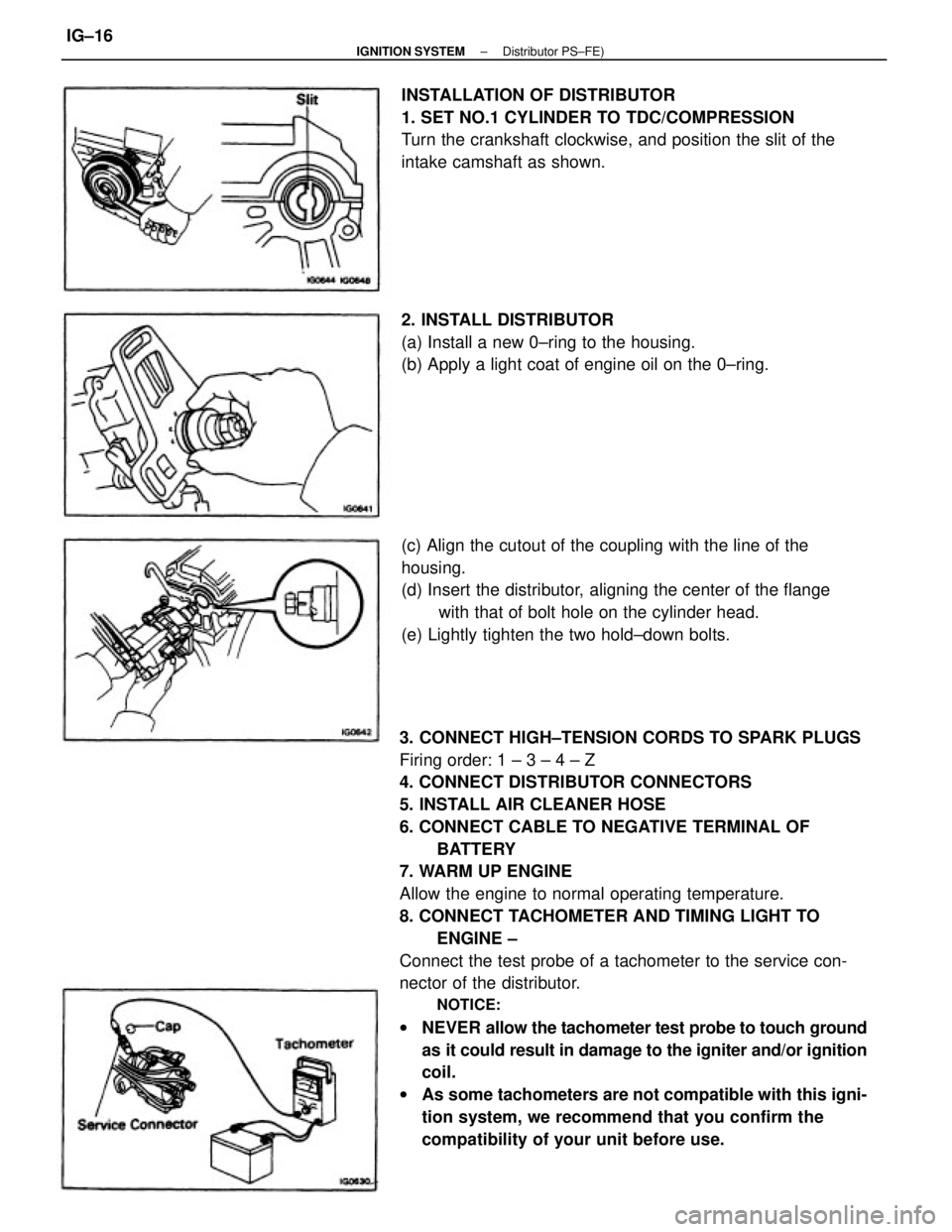
3. CONNECT HIGH±TENSION CORDS TO SPARK PLUGS
Firing order: 1 ± 3 ± 4 ± Z
4. CONNECT DISTRIBUTOR CONNECTORS
5. INSTALL AIR CLEANER HOSE
6. CONNECT CABLE TO NEGATIVE TERMINAL OF
BATTERY
7. WARM UP ENGINE
Allow the engine to normal operating temperature.
8. CONNECT TACHOMETER AND TIMING LIGHT TO
ENGINE ±
Connect the test probe of a tachometer to the service con-
nector of the distributor.
NOTICE:
wNEVER allow the tachometer test probe to touch ground
as it could result in damage to the igniter and/or ignition
coil.
wAs some tachometers are not compatible with this igni-
tion system, we recommend that you confirm the
compatibility of your unit before use. (c) Align the cutout of the coupling with the line of the
housing.
(d) Insert the distributor, aligning the center of the flange
with that of bolt hole on the cylinder head.
(e) Lightly tighten the two hold±down bolts. INSTALLATION OF DISTRIBUTOR
1. SET NO.1 CYLINDER TO TDC/COMPRESSION
Turn the crankshaft clockwise, and position the slit of the
intake camshaft as shown.
2. INSTALL DISTRIBUTOR
(a) Install a new 0±ring to the housing.
(b) Apply a light coat of engine oil on the 0±ring.
± IGNITION SYSTEMDistributor PS±FE)IG±16
Page 1852 of 2389
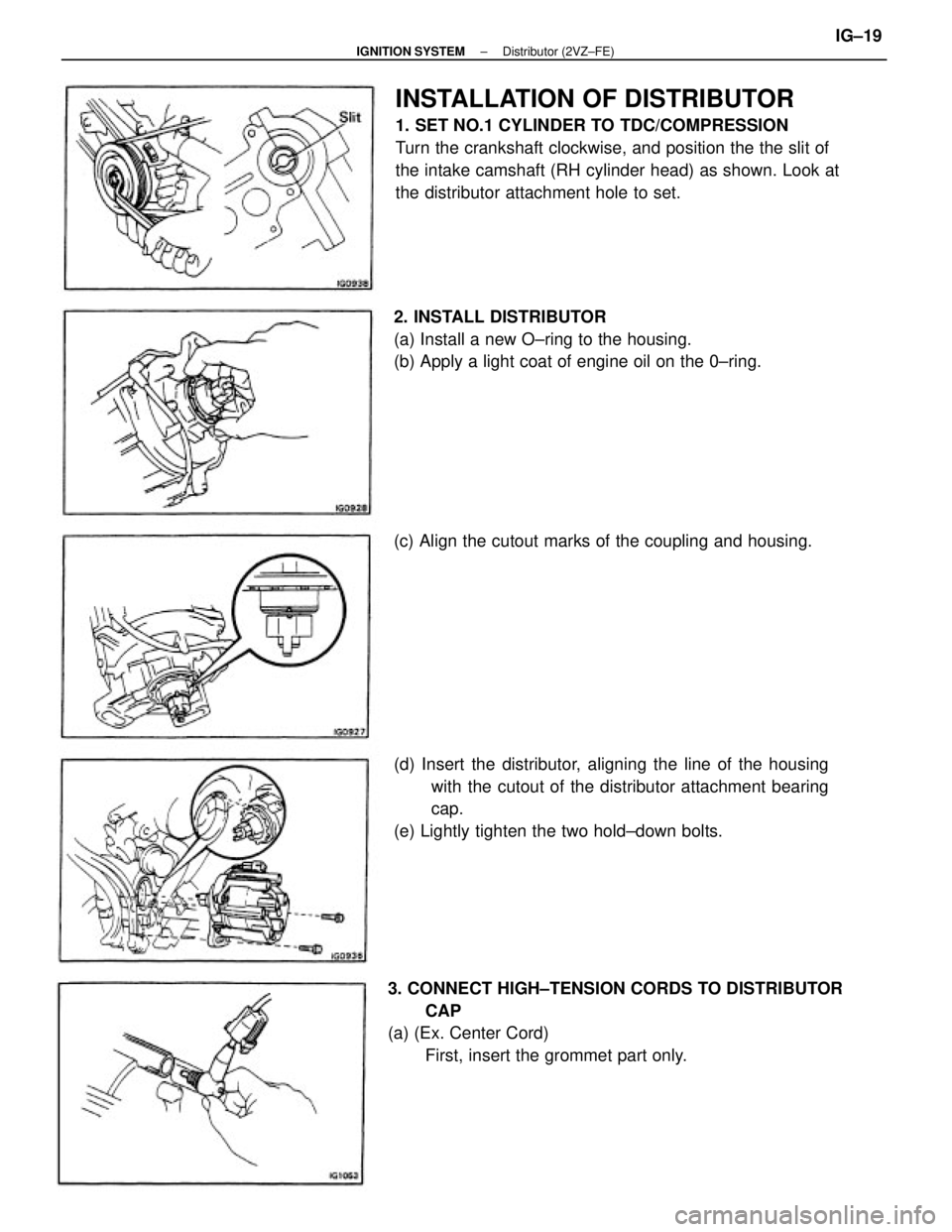
INSTALLATION OF DISTRIBUTOR
1. SET NO.1 CYLINDER TO TDC/COMPRESSION
Turn the crankshaft clockwise, and position the the slit of
the intake camshaft (RH cylinder head) as shown. Look at
the distributor attachment hole to set.
3. CONNECT HIGH±TENSION CORDS TO DISTRIBUTOR
CAP
(a) (Ex. Center Cord)
First, insert the grommet part only. (d) Insert the distributor, aligning the line of the housing
with the cutout of the distributor attachment bearing
cap.
(e) Lightly tighten the two hold±down bolts. 2. INSTALL DISTRIBUTOR
(a) Install a new O±ring to the housing.
(b) Apply a light coat of engine oil on the 0±ring.
(c) Align the cutout marks of the coupling and housing.
± IGNITION SYSTEMDistributor (2VZ±FE)IG±19
Page 2098 of 2389
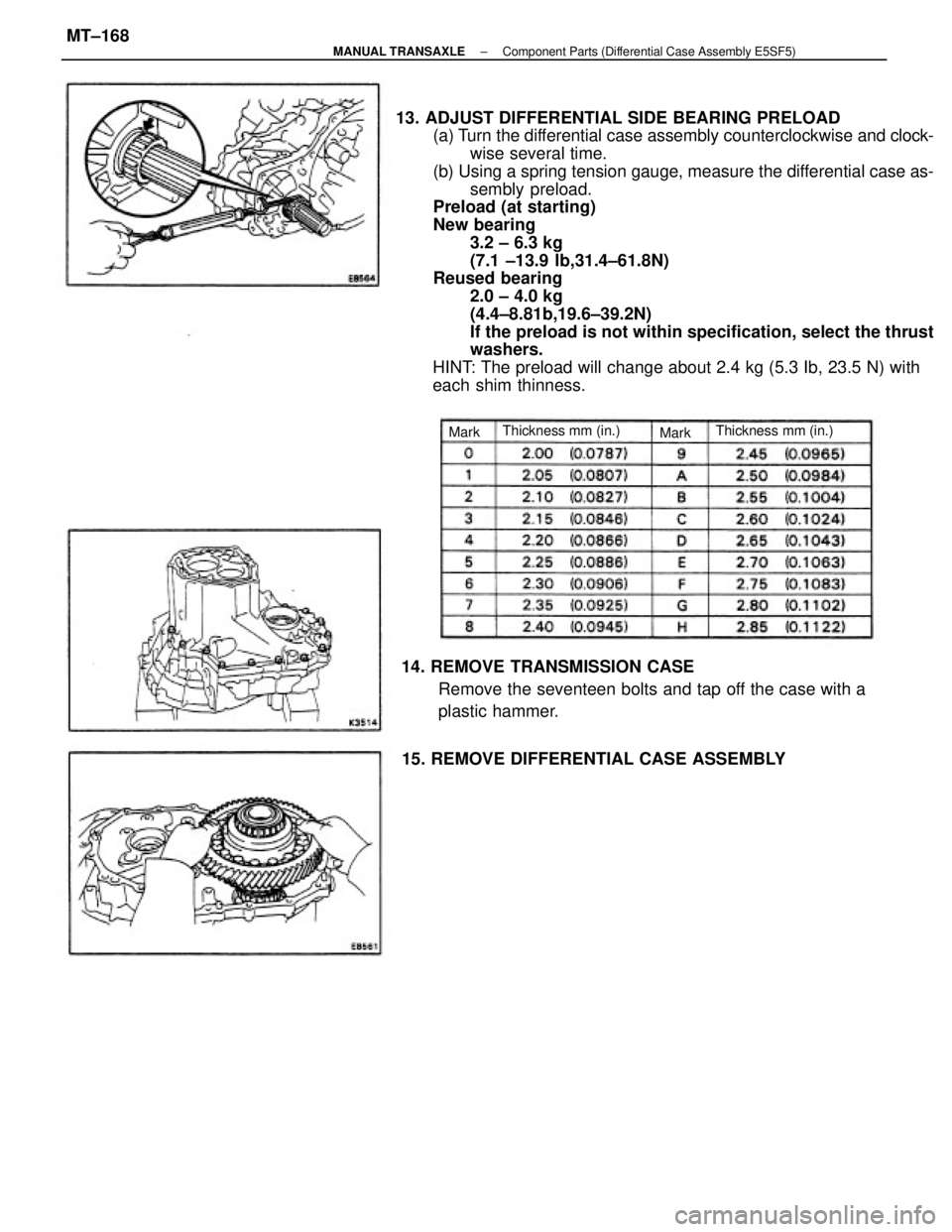
13. ADJUST DIFFERENTIAL SIDE BEARING PRELOAD
(a) Turn the differential case assembly counterclockwise and clock-
wise several time.
(b) Using a spring tension gauge, measure the differential case as-
sembly preload.
Preload (at starting)
New bearing
3.2 ± 6.3 kg
(7.1 ±13.9 lb,31.4±61.8N)
Reused bearing
2.0 ± 4.0 kg
(4.4±8.81b,19.6±39.2N)
If the preload is not within specification, select the thrust
washers.
HINT: The preload will change about 2.4 kg (5.3 Ib, 23.5 N) with
each shim thinness.
14. REMOVE TRANSMISSION CASE
Remove the seventeen bolts and tap off the case with a
plastic hammer.
15. REMOVE DIFFERENTIAL CASE ASSEMBLY
Thickness mm (in.) Thickness mm (in.)
Mark Mark
± MANUAL TRANSAXLEComponent Parts (Differential Case Assembly E5SF5)MT±168
Page 2100 of 2389
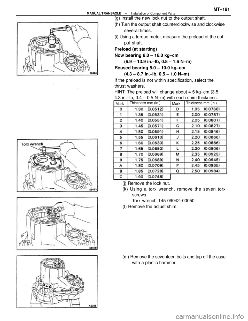
(g) Install the new lock nut to the output shaft.
(h) Turn the output shaft counterclockwise and clockwise
several times.
(i) Using a torque meter, measure the preload of the out-
put shaft.
Preload (at starting)
Now bearing 8.0 ± 16.0 kg±cm
(6.9 ± 13.9 in.±Ib, 0.8 ± 1.6 N±m)
Reused bearing 5.0 ± 10.0 kg±cm
(4.3 ± 8.7 in.±Ib, 0.5 ± 1.0 N±m)
If the preload is not within specification, select the
thrust washers.
HINT: The preload will change about 4 5 kg±cm (3.5
4.3 in.±Ib, 0.4 ± 0.5 N±m) with each shim thickness.
(j) Remove the lock nut.
(k) Using a torx wrench, remove the seven torx
screws.
Torx wrench T45 09042±00050
(I) Remove the adjust shim.
(m) Remove the seventeen bolts and tap off the case
with a plastic hammer.
Thickness mm (in.)
Thickness mm (in.)
Mark Mark
± MANUAL TRANSAXLEInstallation of Component PartsMT±191
Page 2129 of 2389
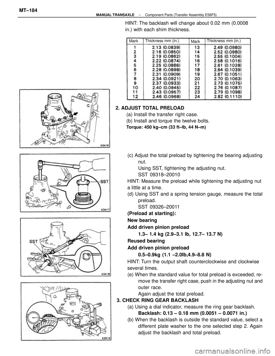
(c) Adjust the total preload by tightening the bearing adjusting
nut.
Using SST, tightening the adjusting nut.
SST 09318±20010
HINT: Measure the preload while tightening the adjusting nut
a little at a time.
(d) Using SST and a spring tension gauge, measure the total
preload.
SST 09326±20011
(Preload at starting):
New bearing
Add driven pinion preload
1.3± 1.4 kg (2.9±3.1 Ib, 12.7± 13.7 N)
Reused bearing
Add driven pinion preload
0.5±0.9kg (1.1 ±2.0Ib,4.9±8.8 N)
HINT: Turn the output shaft counterclockwise and clockwise
several times.
(e) When the standard value for total preload is exceeded, re-
move the transfer right case, push in the adjusting nut and
outer race.
Again adjust the total preload.
3. CHECK RING GEAR BACKLASH
(a) Using a dial indicator, measure the ring gear backlash.
Backlash: 0.13 ± 0.18 mm (0.0051 ± 0.0071 in.)
(b) When the backlash is outside the standard value, select a
different plate washer to the one selected step 2. Again
adjust the backlash and total preload. 2. ADJUST TOTAL PRELOAD
(a) Install the transfer right case.
(b) Install and torque the twelve bolts.
Torque: 450 kg±cm (33 ft±lb, 44 N±m)
HINT: The backlash will change about 0.02 mm (0.0008
in.) with each shim thickness.
Thickness mm (in.) Thickness mm (in.)
Mark
Mark
± MANUAL TRANSAXLEComponent Parts (Transfer Assembly E56F5)MT±184
Page 2316 of 2389
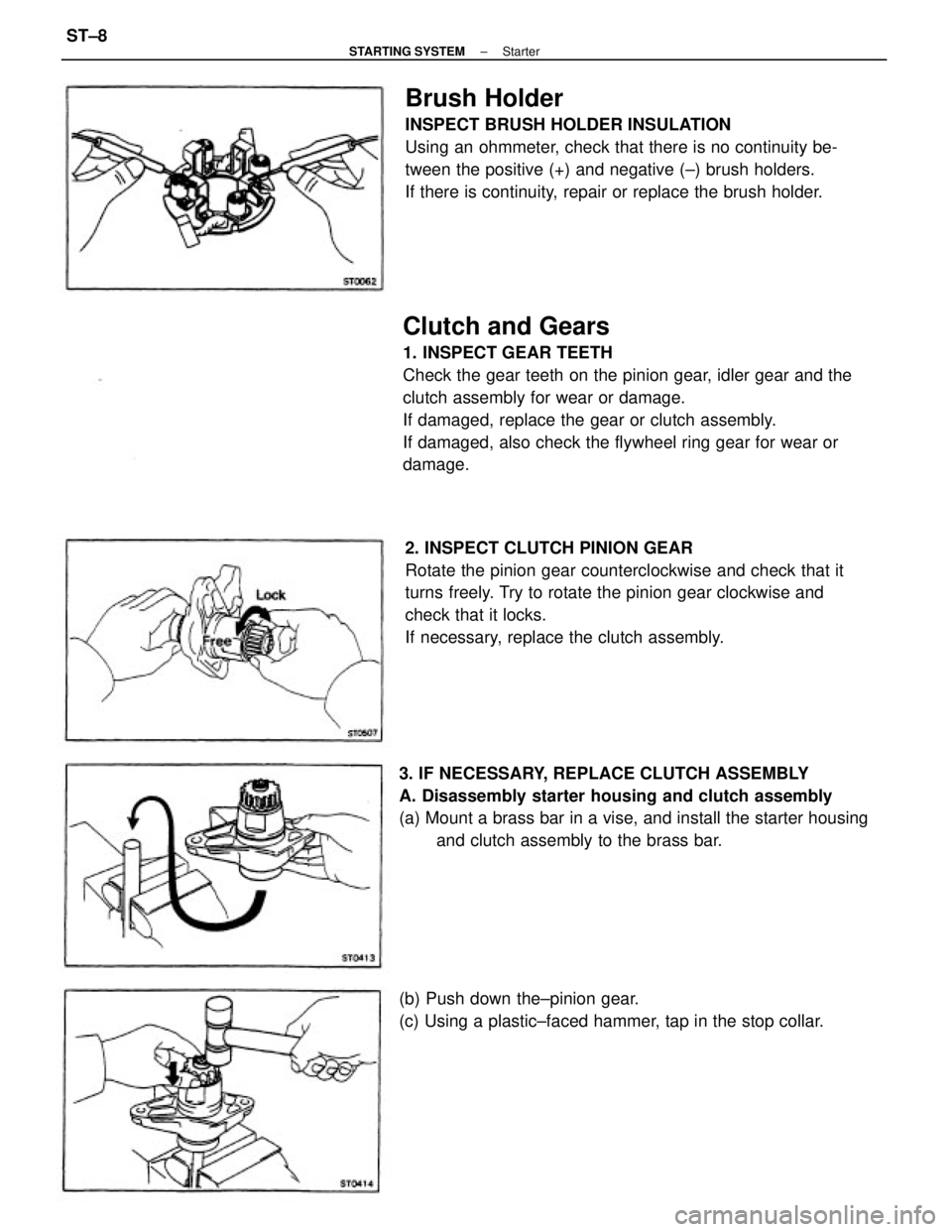
Clutch and Gears
1. INSPECT GEAR TEETH
Check the gear teeth on the pinion gear, idler gear and the
clutch assembly for wear or damage.
If damaged, replace the gear or clutch assembly.
If damaged, also check the flywheel ring gear for wear or
damage.
2. INSPECT CLUTCH PINION GEAR
Rotate the pinion gear counterclockwise and check that it
turns freely. Try to rotate the pinion gear clockwise and
check that it locks.
If necessary, replace the clutch assembly.
Brush Holder
INSPECT BRUSH HOLDER INSULATION
Using an ohmmeter, check that there is no continuity be-
tween the positive (+) and negative (±) brush holders.
If there is continuity, repair or replace the brush holder.
3. IF NECESSARY, REPLACE CLUTCH ASSEMBLY
A. Disassembly starter housing and clutch assembly
(a) Mount a brass bar in a vise, and install the starter housing
and clutch assembly to the brass bar.
(b) Push down the±pinion gear.
(c) Using a plastic±faced hammer, tap in the stop collar.
± STARTING SYSTEMStarterST±8