clock TOYOTA CAMRY V20 1986 Service Information
[x] Cancel search | Manufacturer: TOYOTA, Model Year: 1986, Model line: CAMRY V20, Model: TOYOTA CAMRY V20 1986Pages: 2389, PDF Size: 84.44 MB
Page 630 of 2389
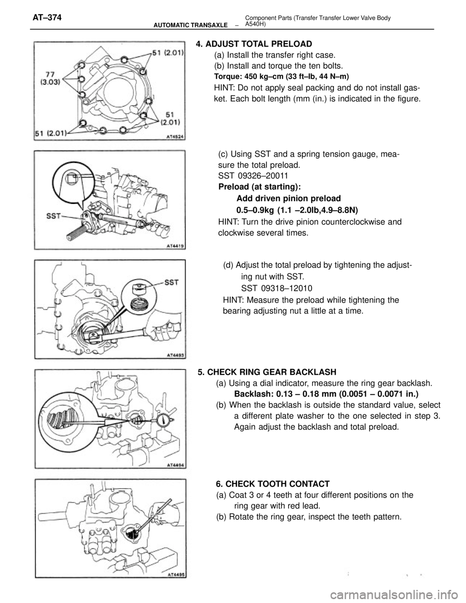
4. ADJUST TOTAL PRELOAD
(a) Install the transfer right case.
(b) Install and torque the ten bolts.
Torque: 450 kg±cm (33 ft±Ib, 44 N±m)
HINT: Do not apply seal packing and do not install gas-
ket. Each bolt length (mm (in.) is indicated in the figure.
(c) Using SST and a spring tension gauge, mea-
sure the total preload.
SST 09326±20011
Preload (at starting):
Add driven pinion preload
0.5±0.9kg (1.1 ±2.0lb,4.9±8.8N)
HINT: Turn the drive pinion counterclockwise and
clockwise several times.
5. CHECK RING GEAR BACKLASH
(a) Using a dial indicator, measure the ring gear backlash.
Backlash: 0.13 ± 0.18 mm (0.0051 ± 0.0071 in.)
(b) When the backlash is outside the standard value, select
a different plate washer to the one selected in step 3.
Again adjust the backlash and total preload. (d) Adjust the total preload by tightening the adjust-
ing nut with SST.
SST 09318±12010
HINT: Measure the preload while tightening the
bearing adjusting nut a little at a time.
6. CHECK TOOTH CONTACT
(a) Coat 3 or 4 teeth at four different positions on the
ring gear with red lead.
(b) Rotate the ring gear, inspect the teeth pattern.
± AUTOMATIC TRANSAXLEComponent Parts (Transfer Transfer Lower Valve Body
A540H)AT±374
Page 644 of 2389
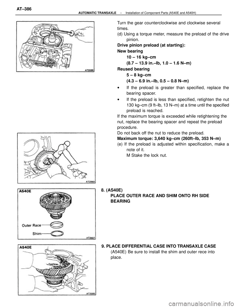
Turn the gear counterclockwise and clockwise several
times.
(d) Using a torque meter, measure the preload of the drive
pinion.
Drive pinion preload (at starting):
New bearing
10 ± 16 kg±cm
(8.7 ± 13.9 in.±Ib, 1.0 ± 1.6 N±m)
Reused bearing
5 ± 8 kg±cm
(4.3 ± 6.9 in.±Ib, 0.5 ± 0.8 N±m)
wIf the preload is greater than specified, replace the
bearing spacer.
wIf the preload is less than specified, retighten the nut
130 kg±cm (9 ft±Ib, 13 N±m) at a time until the specified
preload is reached.
If the maximum torque is exceeded while retightening the
nut, replace the bearing spacer and repeat the preload
procedure.
Do not back off the nut to reduce the preload.
Maximum torque: 3,640 kg±cm (260ft±Ib, 353 N±m)
(e) If the preload is adjusted within specification, make a
note of it.
M Stake the lock nut.
9. PLACE DIFFERENTIAL CASE INTO TRANSAXLE CASE
(A540E) Be sure to install the shim and outer rece into
place. 8. (AS40E)
PLACE OUTER RACE AND SHIM ONTO RH SIDE
BEARING
± AUTOMATIC TRANSAXLEInstallation of Component Parts (A540E and A540H)AT±386
Page 654 of 2389
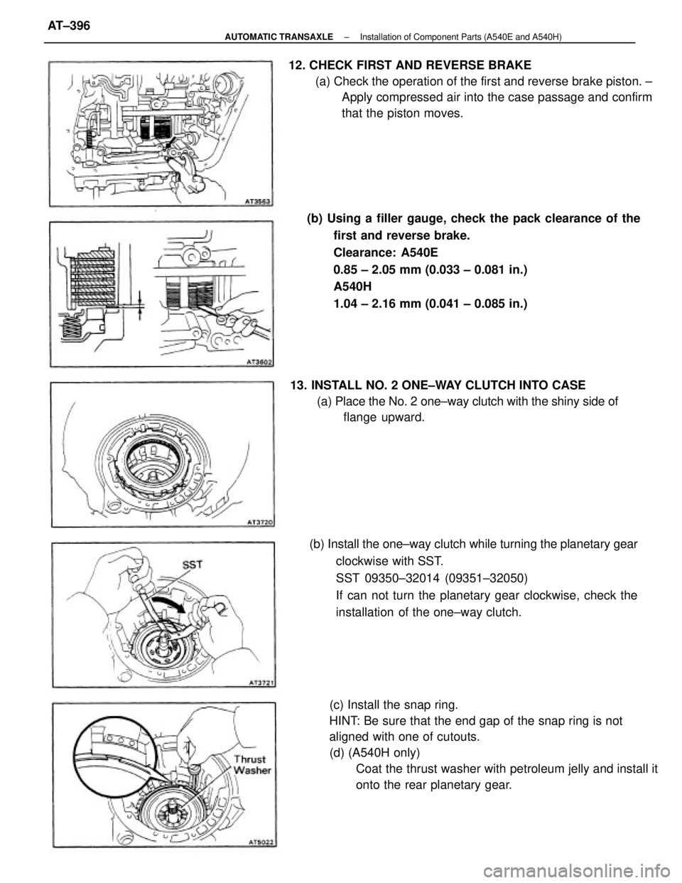
(c) Install the snap ring.
HINT: Be sure that the end gap of the snap ring is not
aligned with one of cutouts.
(d) (A540H only)
Coat the thrust washer with petroleum jelly and install it
onto the rear planetary gear. (b) Using a filler gauge, check the pack clearance of the
first and reverse brake.
Clearance: A540E
0.85 ± 2.05 mm (0.033 ± 0.081 in.)
A540H
1.04 ± 2.16 mm (0.041 ± 0.085 in.) 12. CHECK FIRST AND REVERSE BRAKE
(a) Check the operation of the first and reverse brake piston. ±
Apply compressed air into the case passage and confirm
that the piston moves.
(b) Install the one±way clutch while turning the planetary gear
clockwise with SST.
SST 09350±32014 (09351±32050)
If can not turn the planetary gear clockwise, check the
installation of the one±way clutch. 13. INSTALL NO. 2 ONE±WAY CLUTCH INTO CASE
(a) Place the No. 2 one±way clutch with the shiny side of
flange upward.
± AUTOMATIC TRANSAXLEInstallation of Component Parts (A540E and A540H)AT±396
Page 657 of 2389
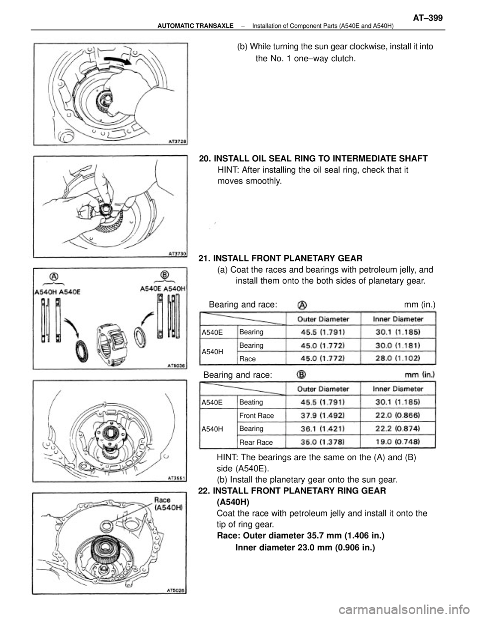
HINT: The bearings are the same on the (A) and (B)
side (A540E).
(b) Install the planetary gear onto the sun gear.
22. INSTALL FRONT PLANETARY RING GEAR
(A540H)
Coat the race with petroleum jelly and install it onto the
tip of ring gear.
Race: Outer diameter 35.7 mm (1.406 in.)
Inner diameter 23.0 mm (0.906 in.) 21. INSTALL FRONT PLANETARY GEAR
(a) Coat the races and bearings with petroleum jelly, and
install them onto the both sides of planetary gear. 20. INSTALL OIL SEAL RING TO INTERMEDIATE SHAFT
HINT: After installing the oil seal ring, check that it
moves smoothly.(b) While turning the sun gear clockwise, install it into
the No. 1 one±way clutch.
Bearing and race:
Front Race
Rear Race Beating Bearing
Bearing Bearing
A540HA540H
A540EA540E
Race
Bearing and race: mm (in.)
± AUTOMATIC TRANSAXLEInstallation of Component Parts (A540E and A540H)AT±399
Page 810 of 2389
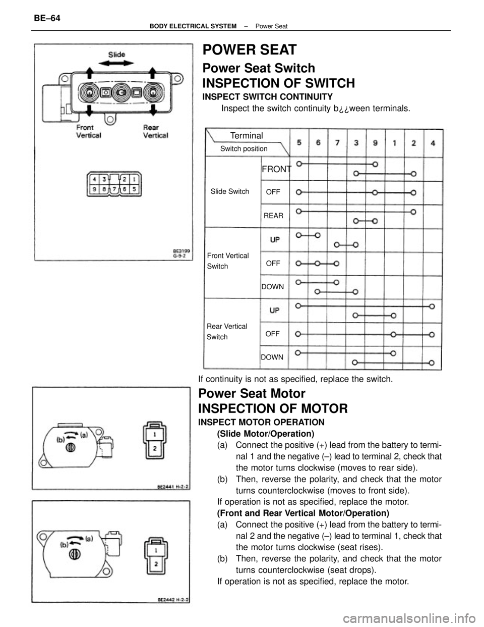
If continuity is not as specified, replace the switch.
Power Seat Motor
INSPECTION OF MOTOR
INSPECT MOTOR OPERATION
(Slide Motor/Operation)
(a) Connect the positive (+) lead from the battery to termi-
nal 1 and the negative (±) lead to terminal 2, check that
the motor turns clockwise (moves to rear side).
(b) Then, reverse the polarity, and check that the motor
turns counterclockwise (moves to front side).
If operation is not as specified, replace the motor.
(Front and Rear Vertical Motor/Operation)
(a) Connect the positive (+) lead from the battery to termi-
nal 2 and the negative (±) lead to terminal 1, check that
the motor turns clockwise (seat rises).
(b) Then, reverse the polarity, and check that the motor
turns counterclockwise (seat drops).
If operation is not as specified, replace the motor.
POWER SEAT
Power Seat Switch
INSPECTION OF SWITCH
INSPECT SWITCH CONTINUITY
Inspect the switch continuity b¿¿ween terminals.
Front Vertical
Switch
Rear Vertical
SwitchSwitch position
Slide Switch
Terminal
FRONT
DOWNDOWNREAROFF
OFFOFF
± BODY ELECTRICAL SYSTEMPower SeatBE±64
Page 825 of 2389
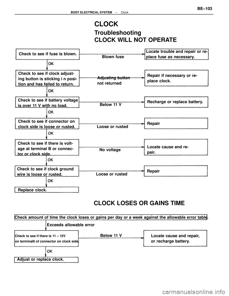
CLOCK
Troubleshooting
CLOCK WILL NOT OPERATE
Check amount of time the clock loses or gains per day or a week against the allowable error table.
Check to see if there is 11 ± 15V
on terminal6 of connector on clock side.
Check to see if clock adjust-
ing button is sticking i n posi-
tion and has failed to return.
Check to see if there is volt-
age at terminal B or connec-
tor or clock side.
Check to see if clock ground
wire is loose or rusted.Check to see if battery voltage
is over 11 V with no load.Repair if necessary or re-
place clock. Locate trouble and repair or re-
place fuse as necessary.
Locate cause and repair,
or recharge battery. Check to see if connector on
clock side is loose or rusted.
CLOCK LOSES OR GAINS TIME
Adjusting button
not returned Check to see if fuse is blown.
Recharge or replace battery.
Adjust or replace clock.Locate cause and re-
pair.
Exceeds allowable errorLoose or rustedLoose or rusted
Replace clock.No voltageBlown fuse
Below 11 V
Below 11 VRepair
Repair
± BODY ELECTRICAL SYSTEMClockBE±103
Page 826 of 2389
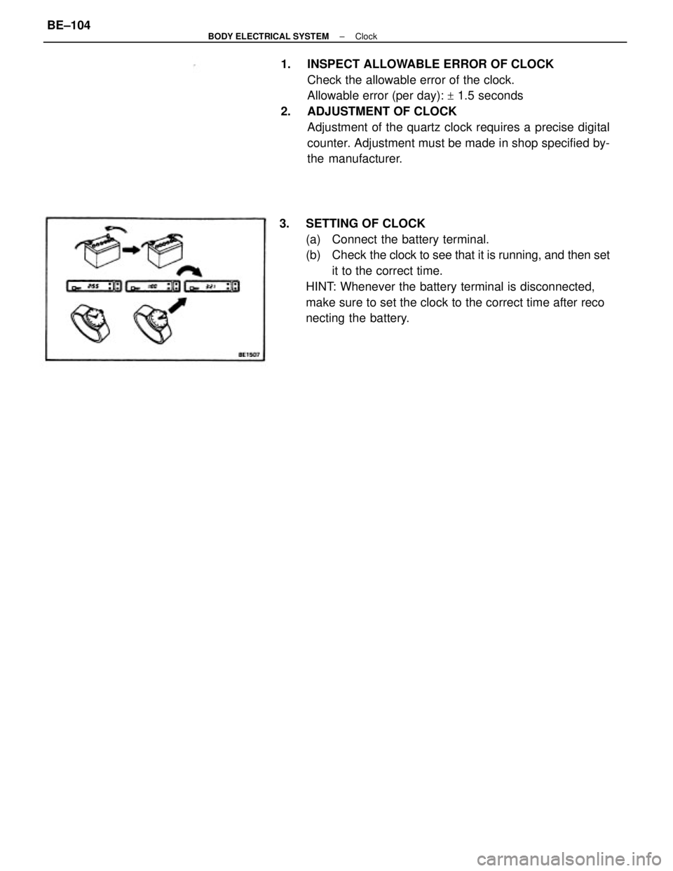
1. INSPECT ALLOWABLE ERROR OF CLOCK
Check the allowable error of the clock.
Allowable error (per day):
+ 1.5 seconds
2. ADJUSTMENT OF CLOCK
Adjustment of the quartz clock requires a precise digital
counter. Adjustment must be made in shop specified by-
the manufacturer.
3. SETTING OF CLOCK
(a) Connect the battery terminal.
(b) Check the clock to see that it is running, and then set
it to the correct time.
HINT: Whenever the battery terminal is disconnected,
make sure to set the clock to the correct time after reco
necting the battery.
± BODY ELECTRICAL SYSTEMClockBE±104
Page 966 of 2389
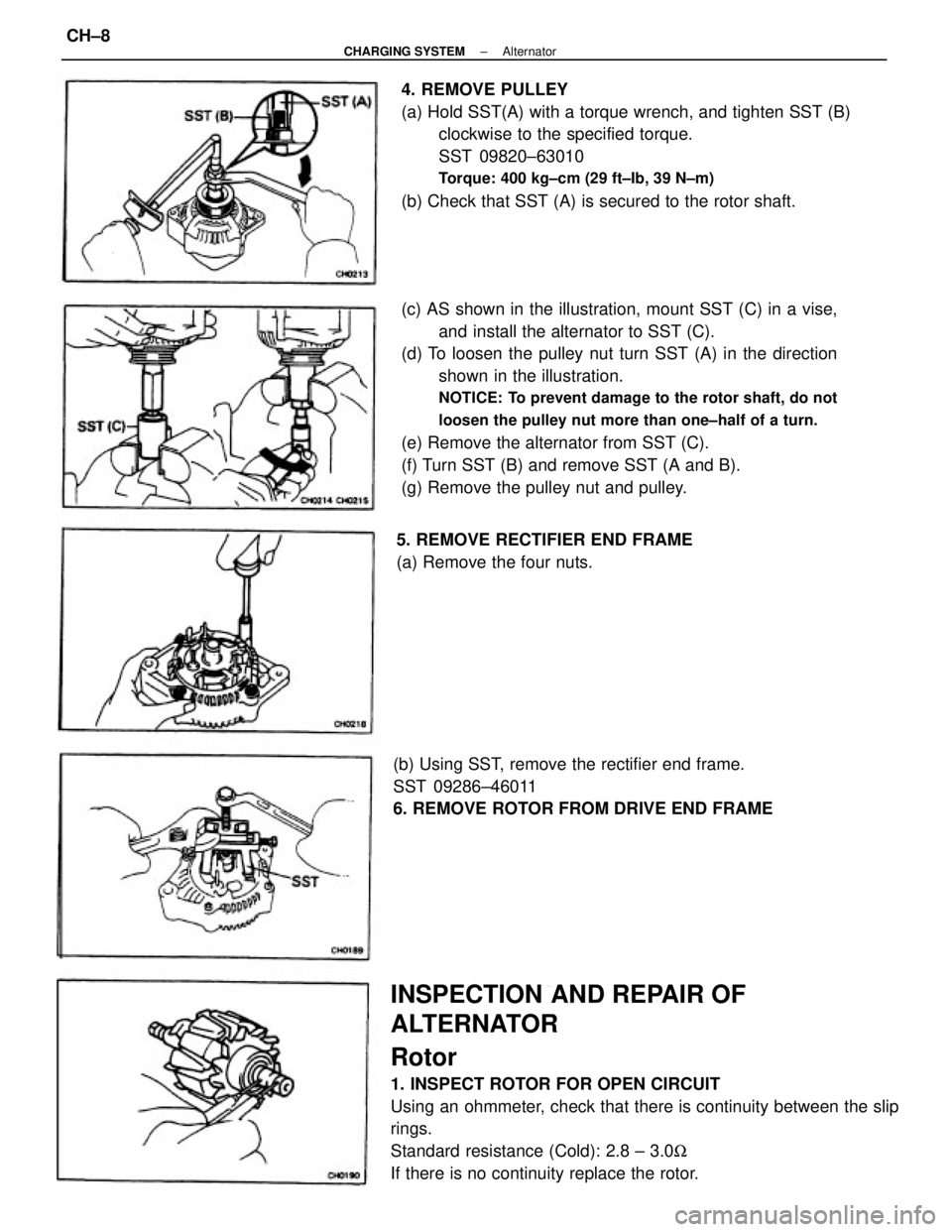
(c) AS shown in the illustration, mount SST (C) in a vise,
and install the alternator to SST (C).
(d) To loosen the pulley nut turn SST (A) in the direction
shown in the illustration.
NOTICE: To prevent damage to the rotor shaft, do not
loosen the pulley nut more than one±half of a turn.
(e) Remove the alternator from SST (C).
(f) Turn SST (B) and remove SST (A and B).
(g) Remove the pulley nut and pulley.
INSPECTION AND REPAIR OF
ALTERNATOR
Rotor
1. INSPECT ROTOR FOR OPEN CIRCUIT
Using an ohmmeter, check that there is continuity between the slip
rings.
Standard resistance (Cold): 2.8 ± 3.0W
If there is no continuity replace the rotor.4. REMOVE PULLEY
(a) Hold SST(A) with a torque wrench, and tighten SST (B)
clockwise to the specified torque.
SST 09820±63010
Torque: 400 kg±cm (29 ft±Ib, 39 N±m)
(b) Check that SST (A) is secured to the rotor shaft.
(b) Using SST, remove the rectifier end frame.
SST 09286±46011
6. REMOVE ROTOR FROM DRIVE END FRAME5. REMOVE RECTIFIER END FRAME
(a) Remove the four nuts.
± CHARGING SYSTEMAlternatorCH±8
Page 970 of 2389
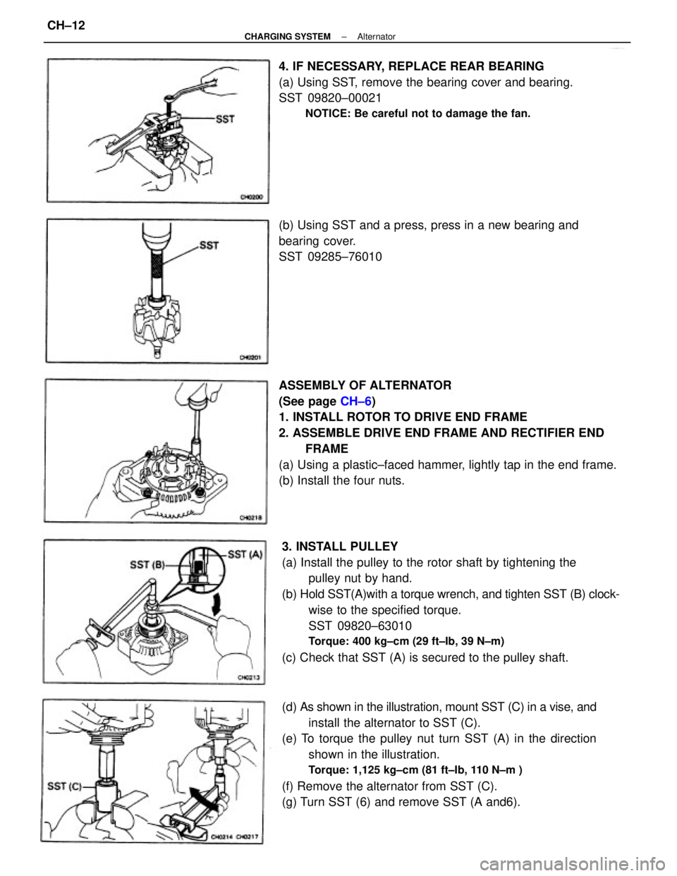
ASSEMBLY OF ALTERNATOR
(See page CH±6)
1. INSTALL ROTOR TO DRIVE END FRAME
2. ASSEMBLE DRIVE END FRAME AND RECTIFIER END
FRAME
(a) Using a plastic±faced hammer, lightly tap in the end frame.
(b) Install the four nuts.
3. INSTALL PULLEY
(a) Install the pulley to the rotor shaft by tightening the
pulley nut by hand.
(b) Hold SST(A)with a torque wrench, and tighten SST (B) clock-
wise to the specified torque.
SST 09820±63010
Torque: 400 kg±cm (29 ft±Ib, 39 N±m)
(c) Check that SST (A) is secured to the pulley shaft.
(d) As shown in the illustration, mount SST (C) in a vise, and
install the alternator to SST (C).
(e) To torque the pulley nut turn SST (A) in the direction
shown in the illustration.
Torque: 1,125 kg±cm (81 ft±Ib, 110 N±m )
(f) Remove the alternator from SST (C).
(g) Turn SST (6) and remove SST (A and6). 4. IF NECESSARY, REPLACE REAR BEARING
(a) Using SST, remove the bearing cover and bearing.
SST 09820±00021
NOTICE: Be careful not to damage the fan.
(b) Using SST and a press, press in a new bearing and
bearing cover.
SST 09285±76010
± CHARGING SYSTEMAlternatorCH±12
Page 1038 of 2389
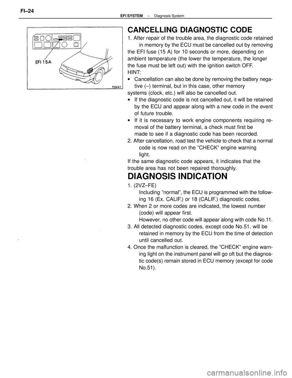
CANCELLING DIAGNOSTIC CODE
1. After repair of the trouble area, the diagnostic code retained
in memory by the ECU must be cancelled out by removing
the EFI fuse (15 A) for 10 seconds or more, depending on
ambient temperature (the lower the temperature, the longer
the fuse must be left out) with the ignition switch OFF.
HINT:
wCancellation can also be done by removing the battery nega-
tive (±) terminal, but in this case, other memory
systems (clock, etc.) will also be cancelled out.
wIf the diagnostic code is not cancelled out, it will be retained
by the ECU and appear along with a new code in the event
of future trouble.
wIf it is necessary to work engine components requiring re-
moval of the battery terminal, a check must first be
made to see if a diagnostic code has been recorded.
2. After cancellation, road test the vehicle to check that a normal
code is now read on the ºCHECKº engine warning
light.
If the same diagnostic code appears, it indicates that the
trouble area has not been repaired thoroughly.
DIAGNOSIS INDICATION
1. (2VZ±FE)
Including ºnormalº, the ECU is programmed with the follow-
ing 16 (Ex. CALIF.) or 18 (CALIF.) diagnostic codes.
2. When 2 or more codes are indicated, the lowest number
(code) will appear first.
However, no other code will appear along with code No.11.
3. All detected diagnostic codes, except code No.51, will be
retained in memory by the ECU from the time of detection
until cancelled out.
4. Once the malfunction is cleared, the ºCHECKº engine warn-
ing light on the instrument panel will go oft but the diagnos-
tic code(s) remain stored in ECU memory (except for code
No.51).
± EFI SYSTEMDiagnosis SystemFI±24