TOYOTA CAMRY V20 1986 Service Information
Manufacturer: TOYOTA, Model Year: 1986, Model line: CAMRY V20, Model: TOYOTA CAMRY V20 1986Pages: 2389, PDF Size: 84.44 MB
Page 2221 of 2389

Connecting rod cap x Connecting rod
Rear oil seal retainer x Cylinder block
No. 2 idler pulley bracket x Cylinder block
Water by±pass pipe x Cylinder block
Rear end plate x Cylinder block
Flywheel x Crankshaft
Drive plate x Crankshaft
Engine RH mounting insulator x Engine mounting bracket
Engine RH mounting insulator x Body Bolt
Nut
Engine LH mounting insulator x Engine mounting bracket
Engine LH mounting insulator x Body
No. 1 engine RH mounting stay x Air intake chamber
No. 1 engine RH mounting stay x Engine RH mounting insu-
lator
No. 2 engine RH mounting stay x Alternator
No. 2 engine RH mounting stay x Engine RH mounting insu-
lator
Engine LH mounting stay x Transaxle M/T
Engine LH mounting stay x Engine mounting insulator
Engine front mounting insulator x Cylinder block
Engine front mounting insulator x Transaxle
Engine front mounting insulator x Engine mounting bracket
Engine center mounting bracket x Cylinder block
Engine rear mounting insulator x Transaxle
Engine rear mounting insulator x Engine mounting bracket
Engine mounting center member x Body
Engine mounting center member x Engine front mounting
insulator
Engine mounting center member x Engine center mounting
insulator
Engine mounting center member x Engine rear mounting
insulator
Exhaust front pipe x Exhaust manifold
Exhaust front pipe x Catalytic converter
Suspension lower crossmember x Body
Suspension lower crossmember x Engine mounting center
memberEGR pipe x EGR valve
EGR pipe x RH exhaust manifold
Main bearing cap x Cylinder block
Torque Specifications (Cont'd)
Part tightened
A/T
± SERVICE SPECIFICATIONSEngine Mechanical (2112±FE)A±10
Page 2222 of 2389
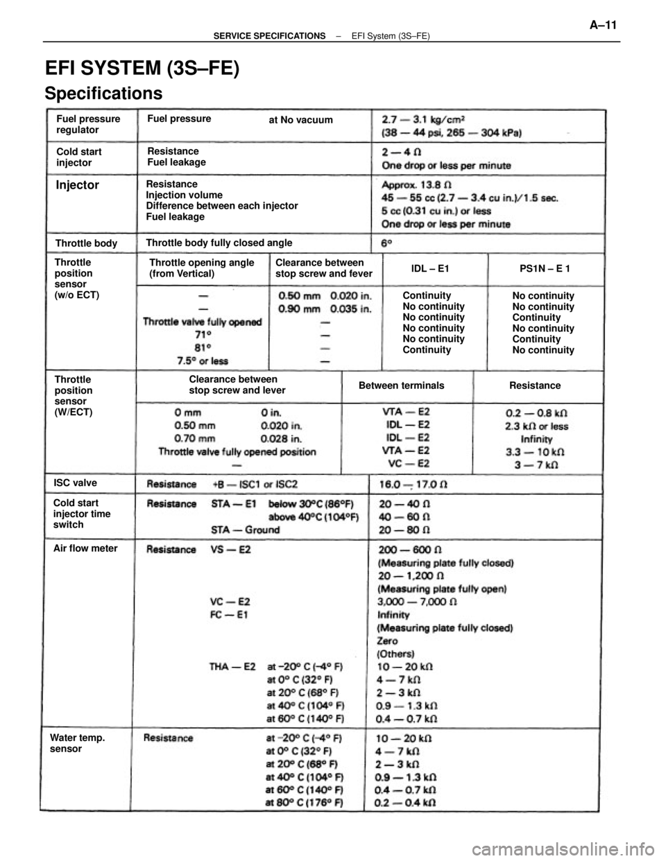
Resistance
Injection volume
Difference between each injector
Fuel leakage
EFI SYSTEM (3S±FE)
Specifications
No continuity
No continuity
Continuity
No continuity
Continuity
No continuity Continuity
No continuity
No continuity
No continuity
No continuity
Continuity Throttle opening angle
(from Vertical)Clearance between
stop screw and fever
Clearance between
stop screw and lever Throttle
position
sensor
(w/o ECT)Throttle body fully closed angle
Cold start
injector time
switchThrottle
position
sensor
(W/ECT)Fuel pressure
regulator
Resistance
Fuel leakage
Water temp.
sensorBetween terminals Cold start
injector
Air flow meterFuel pressure
Throttle bodyat No vacuum
ResistancePS1N ± E 1
ISC valvelDL ± E1
Injector
± SERVICE SPECIFICATIONSEFI System (3S±FE)A±11
Page 2223 of 2389
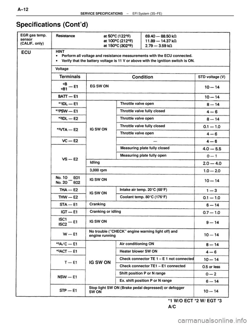
HINT
wPerform all voltage and resistance measurements with the ECU connected.
wVerify that the battery voltage is 11 V or above with the ignition switch is ON.
Stop light SW ON (Brake pedal depressed) or defogger
SW ONNo trouble (ºCHECKº engine warning light off) and
engine running
Check connector TE 1 ± E 1 not connected
Specifications (Cont'd)
Check connector TE1 ± E1 connected
*1 W/O ECT *2 W/ EGT *3
A/C
EGR gas temp.
sensor
(CALIF.. only)
Ex. shift position P or N rangeIntake air temp. 205C (685F) Measuring plate fully closed
Coolant temp. 805C (1765F)
Shift position P or N rangeMeasuring plate fully open Throttle valve fully closed
Throttle valve fully closed
Heater blower SW ON Air conditioning ONThrottle valve open
Throttle valve open
Throttle valve open
Cranking or idlingSTD voltage (V)
3,000 rpmEG SW ON
IG SW ON IG SW ONIG SW ONIG SW ON
IG SW ON
Cranking
Terminals
Condition
Voltage
Idling
ECU
± SERVICE SPECIFICATIONSEFI System (3S±FE)A±12
Page 2224 of 2389

Fuel tank band x Body
Cold start injector x Air intake chamber
Cold start injector pipe x Cold start injector
Cold start injector pipe x Delivery pipe
Fuel pressure regulator X Delivery pipe
Fuel return pipe x Fuel pressure regulator
Delivery pipe x Cylinder head
Throttle body x Air intake chamberFuel evaporation vent tube x Fuel tank 4WD
Fuel inlet pipe x Fuel tankFuel sender gauge
Fuel pump X Fuel tank
Specifications (Cont'd)
Torque Specifications
Coolant temp. 805C (1765F) Intake air temp. 205C (685F) Measuring plate fully closed
Measuring plate fully openThrottle valve fully closed
Throttle valve fully closedThrottle valve fully closedThrottle valve fully closed
Throttle valve fully openThrottle valve fully open
* 1 w/o ECT *2 w/ ECT Throttle valve openThrottle valve open
Part tightened ECU (cont'd) Resistance
Condition
Fuel line
± SERVICE SPECIFICATIONSEFI System (3S±FE)A±13
Page 2225 of 2389
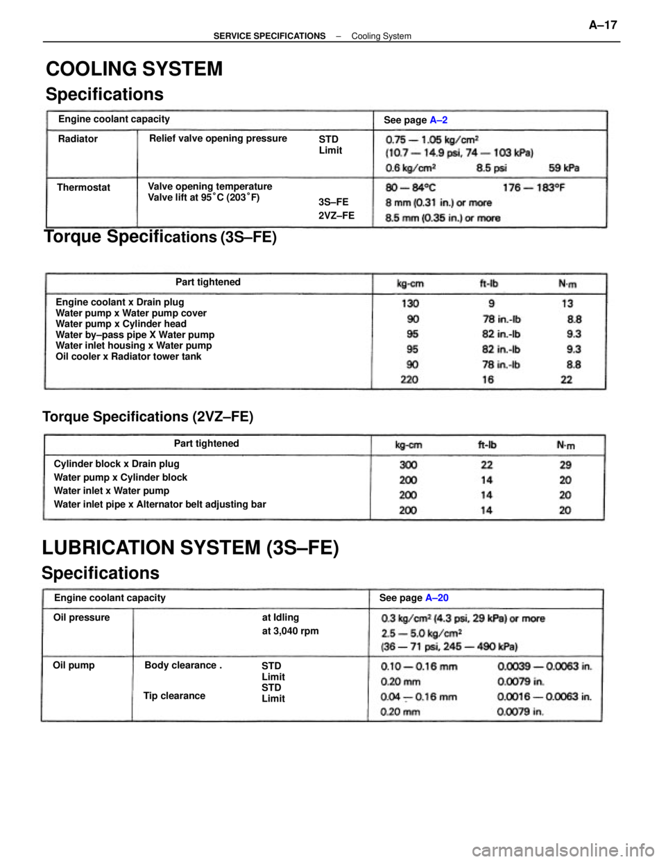
Engine coolant x Drain plug
Water pump x Water pump cover
Water pump x Cylinder head
Water by±pass pipe X Water pump
Water inlet housing x Water pump
Oil cooler x Radiator tower tank
Cylinder block x Drain plug
Water pump x Cylinder block
Water inlet x Water pump
Water inlet pipe x Alternator belt adjusting bar
LUBRICATION SYSTEM (3S±FE)
SpecificationsTorque Specifi
cations (3S±FE)
COOLING SYSTEM
Specifications
Torque Specifications (2VZ±FE)
Valve opening temperature
Valve lift at 95°C (203°F) Relief valve opening pressure
Engine coolant capacityEngine coolant capacity
at Idling
at 3,040 rpm
STD
Limit
STD
Limit Body clearance .See page A±20 STD
Limit
Part tightened
Part tightenedSee page A±2
Tip clearance3S±FE
2VZ±FE
Oil pressureThermostat
Oil pumpRadiator
± SERVICE SPECIFICATIONSCooling SystemA±17
Page 2226 of 2389
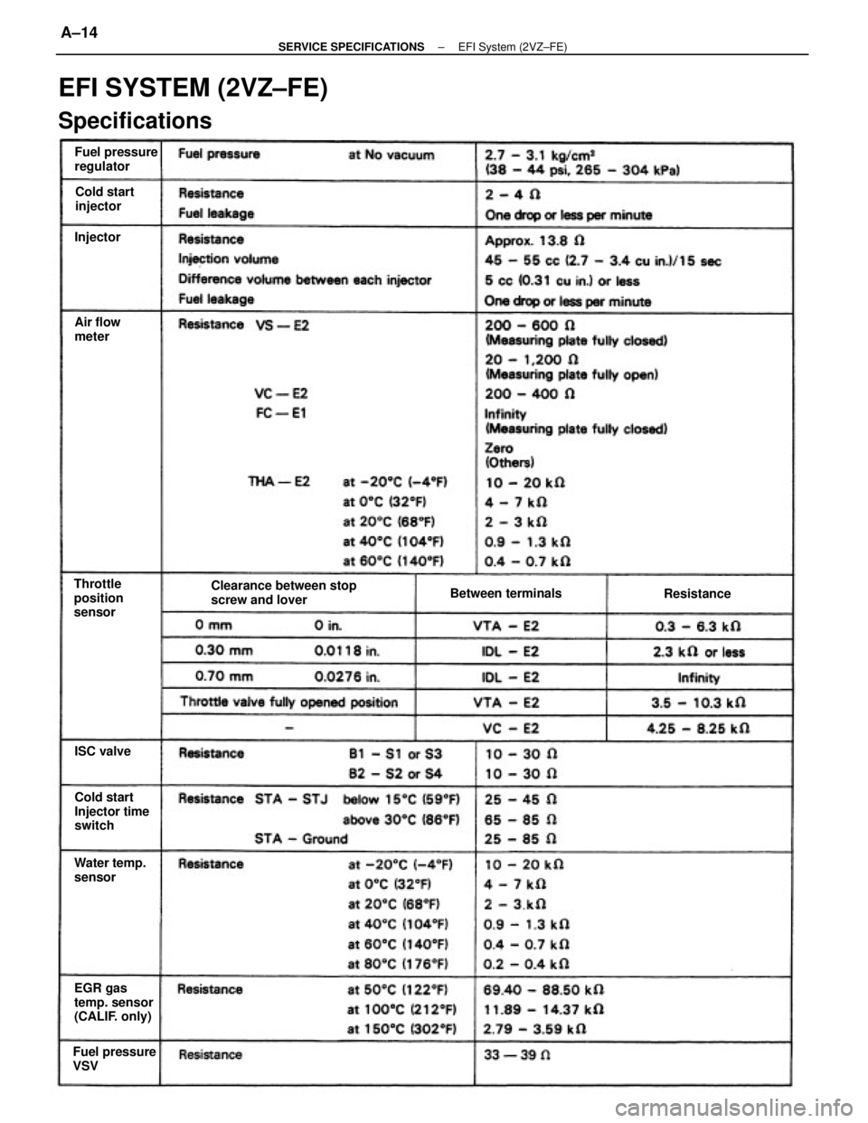
EFI SYSTEM (2VZ±FE)
Specifications
Clearance between stop
screw and lover
EGR gas
temp. sensor
(CALIF. only)Cold start
Injector time
switch Fuel pressure
regulator
Fuel pressure
VSVWater temp.
sensor Throttle
position
sensorBetween terminals Cold start
injector
Air flow
meter
Resistance
ISC valve Injector
± SERVICE SPECIFICATIONSEFI System (2VZ±FE)A±14
Page 2227 of 2389
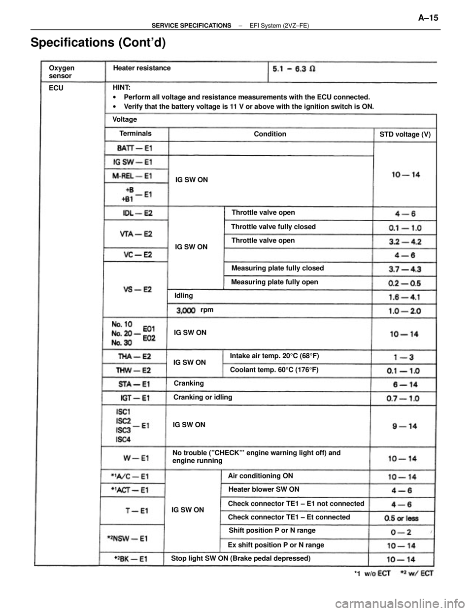
HINT:
wPerform all voltage and resistance measurements with the ECU connected.
wVerify that the battery voltage is 11 V or above with the ignition switch is ON.
No trouble (ºCHECKº' engine warning light off) and
engine running
Specifications (Cont'd)
Stop light SW ON (Brake pedal depressed)Check connector TE1 ± E1 not connected
Check connector TE1 ± Et connected
Shift position P or N range
Ex shift position P or N rangeIntake air temp. 205C (685F) Measuring plate fully closed
Coolant temp. 605C (1765F) Measuring plate fully open Throttle valve fully closed
Heater blower SW ON Air conditioning ONThrottle valve open
Throttle valve open
Cranking or idling Heater resistance
STD voltage (V) Oxygen
sensor
IG SW ON
IG SW ONIG SW ON
IG SW ONIG SW ON
IG SW ONCranking Terminals
Condition Voltage
Idling
*1 w/ rpm ECU
± SERVICE SPECIFICATIONSEFI System (2VZ±FE)A±15
Page 2228 of 2389
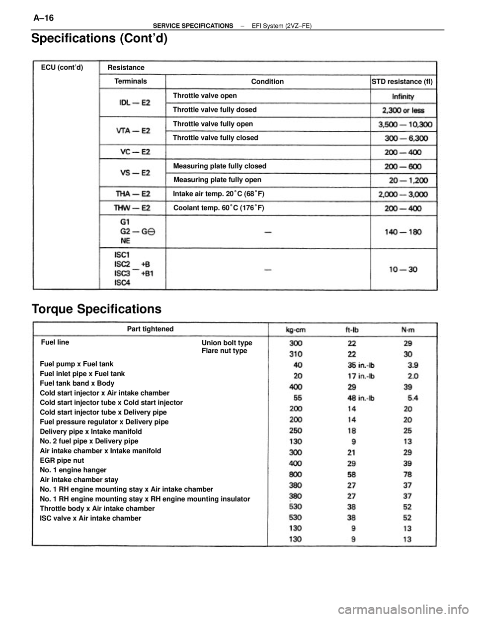
Fuel pump x Fuel tank
Fuel inlet pipe x Fuel tank
Fuel tank band x Body
Cold start injector x Air intake chamber
Cold start injector tube x Cold start injector
Cold start injector tube x Delivery pipe
Fuel pressure regulator x Delivery pipe
Delivery pipe x Intake manifold
No. 2 fuel pipe x Delivery pipe
Air intake chamber x Intake manifold
EGR pipe nut
No. 1 engine hanger
Air intake chamber stay
No. 1 RH engine mounting stay x Air intake chamber
No. 1 RH engine mounting stay x RH engine mounting insulator
Throttle body x Air intake chamber
ISC valve x Air intake chamber
Specifications (Cont'd)
Torque Specifications
Intake air temp. 20°C (68°F) Measuring plate fully closed
Coolant temp. 60°C (176°F)
Union bolt type
Flare nut type Measuring plate fully open Throttle valve fully dosed
Throttle valve fully closedThrottle valve fully open Throttle valve openSTD resistance (fl)
Part tightened ECU (cont'd)
Resistance
Terminals
Condition
Fuel line
± SERVICE SPECIFICATIONSEFI System (2VZ±FE)A±16
Page 2229 of 2389
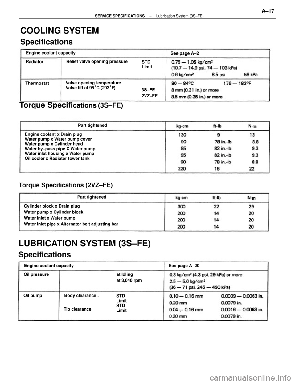
Engine coolant x Drain plug
Water pump x Water pump cover
Water pump x Cylinder head
Water by±pass pipe X Water pump
Water inlet housing x Water pump
Oil cooler x Radiator tower tank
Cylinder block x Drain plug
Water pump x Cylinder block
Water inlet x Water pump
Water inlet pipe x Alternator belt adjusting bar
LUBRICATION SYSTEM (3S±FE)
SpecificationsTorque Specifi
cations (3S±FE)
COOLING SYSTEM
Specifications
Torque Specifications (2VZ±FE)
Valve opening temperature
Valve lift at 95°C (203°F) Relief valve opening pressure
Engine coolant capacityEngine coolant capacity
at Idling
at 3,040 rpm
STD
Limit
STD
Limit Body clearance .See page A±20 STD
Limit
Part tightened
Part tightenedSee page A±2
Tip clearance3S±FE
2VZ±FE
Oil pressureThermostat
Oil pumpRadiator
± SERVICE SPECIFICATIONSLubrication System (3S±FE)A±17
Page 2230 of 2389
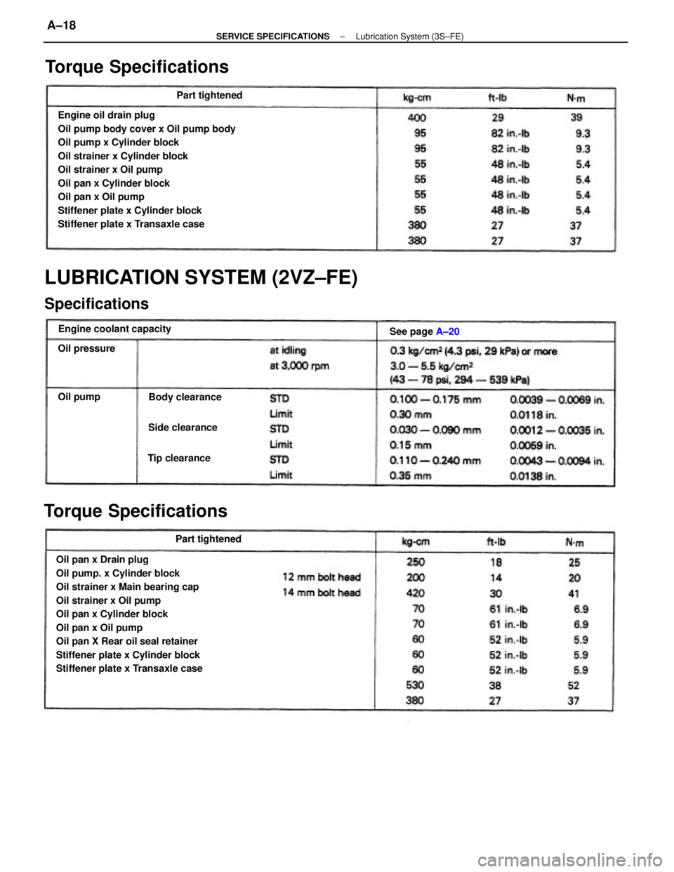
Engine oil drain plug
Oil pump body cover x Oil pump body
Oil pump x Cylinder block
Oil strainer x Cylinder block
Oil strainer x Oil pump
Oil pan x Cylinder block
Oil pan x Oil pump
Stiffener plate x Cylinder block
Stiffener plate x Transaxle case
Oil pan x Drain plug
Oil pump. x Cylinder block
Oil strainer x Main bearing cap
Oil strainer x Oil pump
Oil pan x Cylinder block
Oil pan x Oil pump
Oil pan X Rear oil seal retainer
Stiffener plate x Cylinder block
Stiffener plate x Transaxle case
LUBRICATION SYSTEM (2VZ±FE)
Specifications
Torque SpecificationsTorque Specifications
Engine coolant capacity
Body clearanceSee page A±20
Part tightened Side clearancePart tightened
Tip clearance Oil pressure
Oil pump
± SERVICE SPECIFICATIONSLubrication System (3S±FE)A±18